1997 SSANGYONG KORANDO hood release
[x] Cancel search: hood releasePage 14 of 2053

0B -- 14 GENERAL INFORMATION
D AEW OO M Y_2000
EACH TIME THE OIL IS CHANGED
Brake System Inspection
This inspection should be done when the wheels are re-
moved for rotation. Inspect the lines and the hoses for
proper hookup, binding, leaks, cracks, chafing, etc. In-
spect the disc brake pads for wear. Inspect the rotors for
surface condition. Inspect other brake parts, the parking
brake, etc., at the same time. Inspect the brakes more
often if habit or conditions result in frequent braking.
Steering, Suspension and Front Drive Axle
Boot And Seal Inspection
Inspect the front and rear suspension and the steering
system for damaged, loose or missing parts, signs of
wear or lack of lubrication. Inspect the power steering
line and the hoses for proper hookup, binding, leaks,
cracks, chafing, etc. Clean and inspect the drive axle
boot and seals for damage, tears or leakage. Replace
the seals if necessary.
Exhaust System Inspection
Inspect the complete system (including the catalytic
converter if equipped). Inspect the body near the ex-
haust system. Look for broken, damaged, missing, or
out -- of -- position parts as well as open seams, holes,
loose connections, or other conditions which could
cause heat buildup in the floor pan or could let exhaust
fumes seep into the trunk or passenger compartment.
Throttle Linkage Inspection
Inspect the throttle linkage for interference or binding,
damaged, or missing parts. Lubricate all linkage joints
and throttle cable joints, the intermediate throttle shaft
bearing, the return spring at throttle valve assembly, and
the accelerator pedal sliding face with suitable grease.
Check the throttle cable for free movements.
Engine Drive Belts
Inspect all belts for cracks, fraying, wear and proper ten-
sion. Adjust or replace the belts as needed.
Hood Latch Operation
When opening the hood, note the operation of the sec-
ondary latch. It should keep the hood from opening all
the way when the primary latch is released. The hood
must close firmly.
AT LEAST ANNUALLY
Lap and Shoulder Belts Condition and Operation
Inspect the belt system including: the webbing, the
buckles, the latch plates, the retractor, the guide loops
and the anchors.
Movable Head Restraint Operation
On vehicles with movable head restraints, the restraints
must stay in the desired position.
Spare Tire and Jack Storage
Be alert to rattles in the rear of the vehicle. The spare
tire, all the jacking equipment, and the tools must be se-
curely stowed at all times. Oil the jack ratchet or the
screw mechanism after each use.
Key Lock Service
Lubricate the key lock cylinder.
Body Lubrication Service
Lubricate all the body door hinges including the hood,
the fuel door, the rear compartment hinges and the
latches, the glove box and the console doors, and any
folding seat hardware.
Underbody Flushing
Flushing the underbody will remove any corrosive mate-
rials used for ice and snow removal and dust control. At
least every spring clean the underbody. First, loosen the
sediment packed in closed areas of the vehicle. Then
flush the underbody with plain water.
Engine Cooling System
Inspect the coolant and freeze protection fluid. If the
fluid is dirty or rusty, drain, flush and refill the engine
cooling system with new coolant. Keep the coolant at
the proper mixture in order to ensure proper freeze
protection, corrosion protection and engine operating
temperature. Inspect the hoses. Replace the cracked,
swollen, or deteriorated hoses. Tighten the clamps.
Clean the outside of the radiator and the air conditioning
condenser. Wash the filler cap and the neck. Pressure
test the cooling system and the cap in order to help en-
sure proper operation.
Page 1092 of 2053

PARKING BRAKE 4G-5
SSANGYONG MY2002
KAA4G040
KAA4G050
KAA4G060
KAA4G070
PARKING BRAKE LEVER
Removal and Installation Procedure
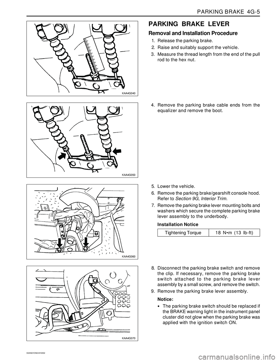
1. Release the parking brake.
2. Raise and suitably support the vehicle.
3. Measure the thread length from the end of the pull
rod to the hex nut.
5. Lower the vehicle.
6. Remove the parking brake/gearshift console hood.
Refer to Section 9G, Interior Trim.
7. Remove the parking brake lever mounting bolts and
washers which secure the complete parking brake
lever assembly to the underbody.
Installation Notice
8. Disconnect the parking brake switch and remove
the clip. If necessary, remove the parking brake
switch attached to the parking brake lever
assembly by a small screw, and remove the switch.
9. Remove the parking brake lever assembly.
Notice:
The parking brake switch should be replaced if
the BRAKE warning light in the instrument panel
cluster did not glow when the parking brake was
applied with the ignition switch ON.
Tightening Torque 18 Nm (13 lb-ft) 4. Remove the parking brake cable ends from the
equalizer and remove the boot.
Page 1718 of 2053

SECTION 9E
INSTRUMENTATION, DRIVER INFORMATION
CAUTION: Disconnect the negative battery cable before removing or installing any electrical unit or when a
tool or equipment could easily come in contact with exposed electrical terminals. Disconnecting this cable
will help prevent personal injury and damage to the vehicle. The ignition must also be in LOCK unless
otherwise noted.
TABLE OF CONTENTS
Description and Operation.................................. 9E-2
Cigar Lighter....................................................... 9E-2
Ashtray.............................................................. 9E-2
Instrument Panel Vents....................................... 9E-2
Glove Box.......................................................... 9E-2
Digital Clock....................................................... 9E-2
Instrument Cluster.............................................. 9E-2
Speedometer and Tachometer............................ 9E-2
Trip Odometer.................................................... 9E-2
Fuel Gauge......................................................... 9E-2
Temperature Gauge............................................ 9E-2
Instrument Cluster Indicator Lamps..................... 9E-2
Chime Module.................................................... 9E-2
Components Locator ........................................... 9E-3
Instrumentation/Driver Information....................... 9E-3
Diagnostic Information and Procedure.............. 9E-5
Cigar Lighter....................................................... 9E-5
Disital Clock....................................................... 9E-5
Speedo Meter..................................................... 9E-6
Fuel Gauge......................................................... 9E-7
Temperature Gauge............................................ 9E-8
Instrument Cluster Indicator Lamps..................... 9E-9
Repair Instructions............................................. 9E-10
On-Vehice Service Unit Repair............................. 9E-10
Center Tray....................................................... 9E-10
Center Facia..................................................... 9E-10
Ashtray............................................................ 9E-10
Cigar Lighter..................................................... 9E-11Cup Holder....................................................... 9E-11
Instrument Panel Vent....................................... 9E-11
Glove Box........................................................ 9E-12
Chime Module.................................................. 9E-12
Hood Latch Release Handle.............................. 9E-12
Instrument Lower Cover.................................... 9E-13
Instrument Cluster Trim Panel........................... 9E-13
Instrument Cluster............................................ 9E-13
Speedometer/Odometer/Trip Odometer/
Tachometer................................................... 9E-14
Fuel Gauge....................................................... 9E-14
Temperature Gauge .......................................... 9E-15
Digital Clock..................................................... 9E-15
Instrument Cluster Indicator Lamps................... 9E-15
Instrument Panel............................................... 9E-16
Specifications.................................................... 9E-18
Bulb Usage Chart............................................. 9E-18
Schematic and Routing Diagram..................... 9E-19
Instrument Panel Illumination............................ 9E-19
Cluster (VSS, Meter & Gauge): Diesel.................9E-20
Cluster (VSS, Meter & Gauge): Gasoline............ 9E-21
Warning Lamp, TCS Indicator........................... 9E-22
Indicator........................................................... 9E-23
Warning Lamp.................................................. 9E-24
Digital Clock, Warning Cluster Illumination......... 9E-25
Selector Lever Position Lamp............................ 9E-26
Page 1729 of 2053

SSANGYONG MY2002
9E-12 INSTRUMENTATION, DRIVER INFORMATION
KAA9E090
KAA9E100
KAA9E110
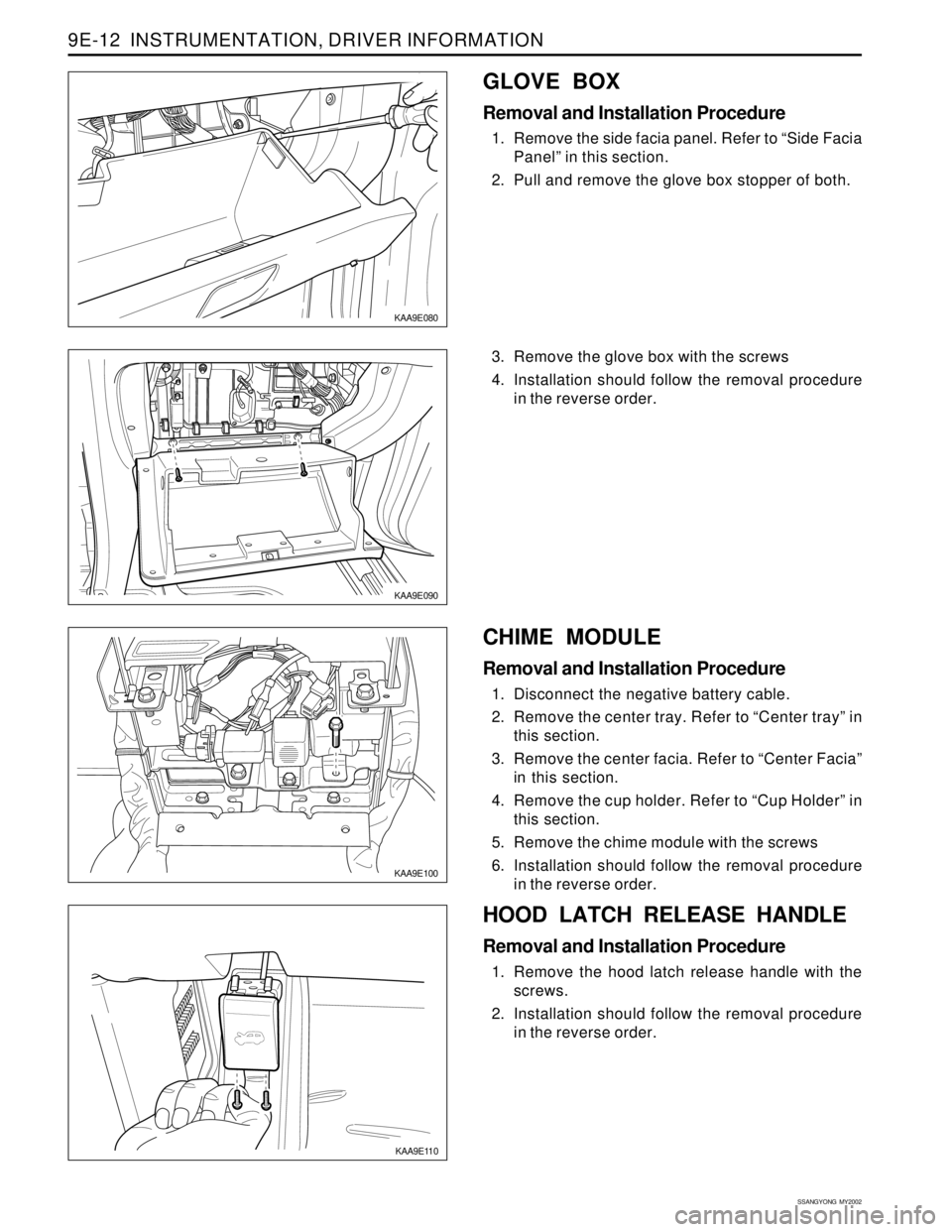
3. Remove the glove box with the screws
4. Installation should follow the removal procedure
in the reverse order.
HOOD LATCH RELEASE HANDLE
Removal and Installation Procedure
1. Remove the hood latch release handle with the
screws.
2. Installation should follow the removal procedure
in the reverse order.
KAA9E080
GLOVE BOX
Removal and Installation Procedure
1. Remove the side facia panel. Refer to “Side Facia
Panel” in this section.
2. Pull and remove the glove box stopper of both.
CHIME MODULE
Removal and Installation Procedure
1. Disconnect the negative battery cable.
2. Remove the center tray. Refer to “Center tray” in
this section.
3. Remove the center facia. Refer to “Center Facia”
in this section.
4. Remove the cup holder. Refer to “Cup Holder” in
this section.
5. Remove the chime module with the screws
6. Installation should follow the removal procedure
in the reverse order.
Page 1730 of 2053

INSTRUMENTATION, DRIVER INFORMATION 9E-13
SSANGYONG MY2002
KAA9E130
KAA9E140
KAA9E150
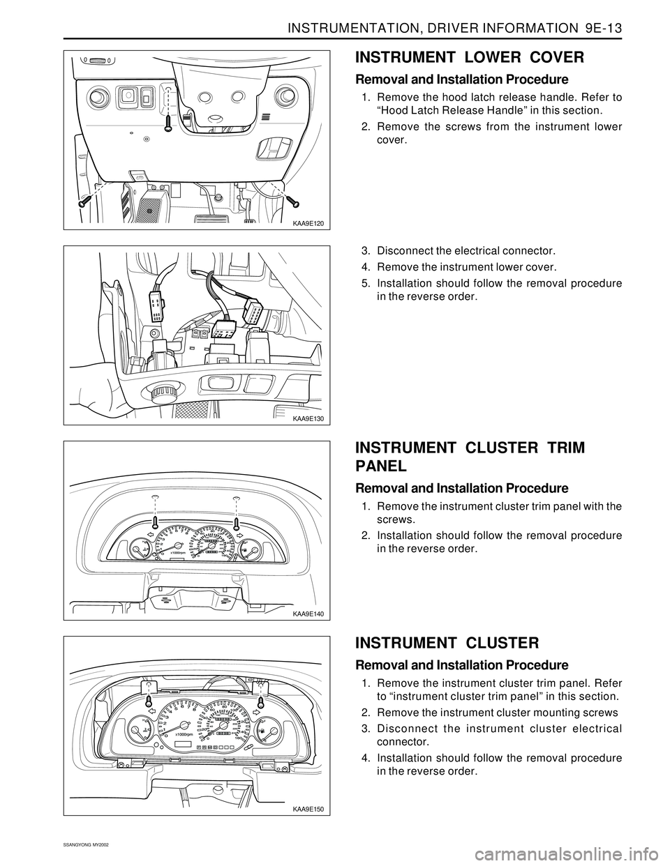
3. Disconnect the electrical connector.
4. Remove the instrument lower cover.
5. Installation should follow the removal procedure
in the reverse order.
INSTRUMENT CLUSTER
Removal and Installation Procedure
1. Remove the instrument cluster trim panel. Refer
to “instrument cluster trim panel” in this section.
2. Remove the instrument cluster mounting screws
3. Disconnect the instrument cluster electrical
connector.
4. Installation should follow the removal procedure
in the reverse order.
KAA9E120
INSTRUMENT LOWER COVER
Removal and Installation Procedure
1. Remove the hood latch release handle. Refer to
“Hood Latch Release Handle” in this section.
2. Remove the screws from the instrument lower
cover.
INSTRUMENT CLUSTER TRIM
PANEL
Removal and Installation Procedure
1. Remove the instrument cluster trim panel with the
screws.
2. Installation should follow the removal procedure
in the reverse order.