1997 SSANGYONG KORANDO air filter
[x] Cancel search: air filterPage 784 of 2053

OM600 ENGINE CONTROLS 1F3 -- 27
D AEW OO M Y_2000
Tools Required
001 589 65 09 00 Socket Wrench Insert
000 589 00 68 00 Cleaning Set
Repair Procedure
1. Clamp the nozzle holder (1) in a vice and remove
the nozzle tensioning nut (8).
Notice
Use protective jaws for clamping.
2. Disassemble the fuel injection nozzle.
Socket Wrench Insert 001 589 65 09 00
3. Clean the nozzle needle (6) and nozzle body (7) with
an abradant.
4. Clean the nozzle seat with cleaning cutter.
Cleaning Set 000 589 00 68 00
5. Immerse nozzle needle (6) and nozzle body (7) in
filtered diesel fuel. When the nozzle body is held
vertical, the weight of the nozzle needle must cause
it to slide down toward the nozzle needle seat.
6. Assemble the injection nozzle so that the tip of the
thrust (4) pin is facing toward the nozzle holder.
Tightening Torque80 N∙m (59 lb-ft)
Notice
Nozzle needle (6) and nozzle body (7) should al-
ways be replaced as a pair.
Page 811 of 2053

1F3 -- 8 OM600 ENGINE CONTROLS
D AEW OO M Y_2000
Detach line downstream of air admission filter
(13).
Vacuum drops
YES
NO
Faulty filter with restriction.
Fit the line onto air admission filter. Built up vacu-
um with vacuum pump. Detach the plug from air
admission line.
YES
NO
Faulty thermovalve
Vacuum drops
Go to test step 2
Page 1289 of 2053
5A-194 AUTOMATIC TRANSMISSION
SSANGYONG MY2002
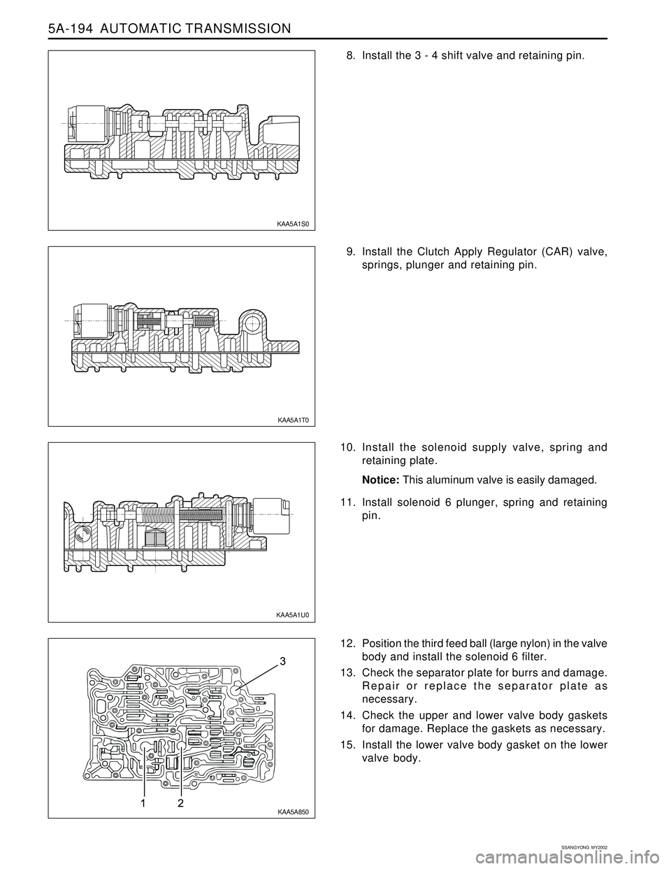
8. Install the 3 - 4 shift valve and retaining pin.
9. Install the Clutch Apply Regulator (CAR) valve,
springs, plunger and retaining pin.
10. Install the solenoid supply valve, spring and
retaining plate.
Notice: This aluminum valve is easily damaged.
11. Install solenoid 6 plunger, spring and retaining
pin.
12. Position the third feed ball (large nylon) in the valve
body and install the solenoid 6 filter.
13. Check the separator plate for burrs and damage.
Repair or replace the separator plate as
necessary.
14. Check the upper and lower valve body gaskets
for damage. Replace the gaskets as necessary.
15. Install the lower valve body gasket on the lower
valve body.
KAA5A1S0
KAA5A1T0
KAA5A1U0
KAA5A850
Page 1502 of 2053
SECTION 7A
HEATING AND VENTILATION SYSTEM
CAUTION: The cooling system is pressurized when hot. Injury can result from removing the coolant reservoir
cap before the engine is sufficiently cool.
TABLE OF CONTENTS
Description and Operation ................................7A-2
Heating and Ventilation System .........................7A-2
Components Locator ..........................................7A-3
Heater System ...................................................7A-3
Diagnostic Information and Procedures ..........7A-4
Heater System ...................................................7A-4
Blower Electrical ................................................7A-8
Mode Controls Do Not Work .............................7A-10
Air Source Selection Not Controlled ..................7A-12
Temperature Controls Do Not Work ..................7A-13
Too Much Heat .................................................7A-14
Blower Noise ....................................................7A-16
Repair Instructions ............................................7A-18
On-Vehicle Service..............................................7A-18
Temperature Control Cable Adjustment ............7A-18
Controller Assembly and Temperature
Control Cable .................................................7A-18
Control Assembly Knob Lighting ......................7A-19Air Intake Door Actuator ...................................7A-19
Mode Control Door Actuator .............................7A-20
Heater/Air Distributor Case Assembly ..............7A-20
Blower Motor ....................................................7A-21
Blower Resistor ................................................7A-22
Blower Unit .......................................................7A-22
Heater Inlet Hose ..............................................7A-23
Heater Outlet Hose ...........................................7A-23
Heater Core......................................................7A-24
Rear Heater Duct ..............................................7A-24
Air Filter ............................................................7A-24
Specifications .................................................... 7A-25
Heater Temperature Specification .....................7A-25
Heater Unit .......................................................7A-25
Fastener Tightening Specification .....................7A-25
Schematic and Routing Diagrams ................... 7A-26
Non - A/C Wiring Diagram ................................7A-26
Airflow Through Vents .......................................7A-28
Page 1507 of 2053
SSANGYONG MY2002
7A-6 HEATING AND VENTILATION SYSTEM
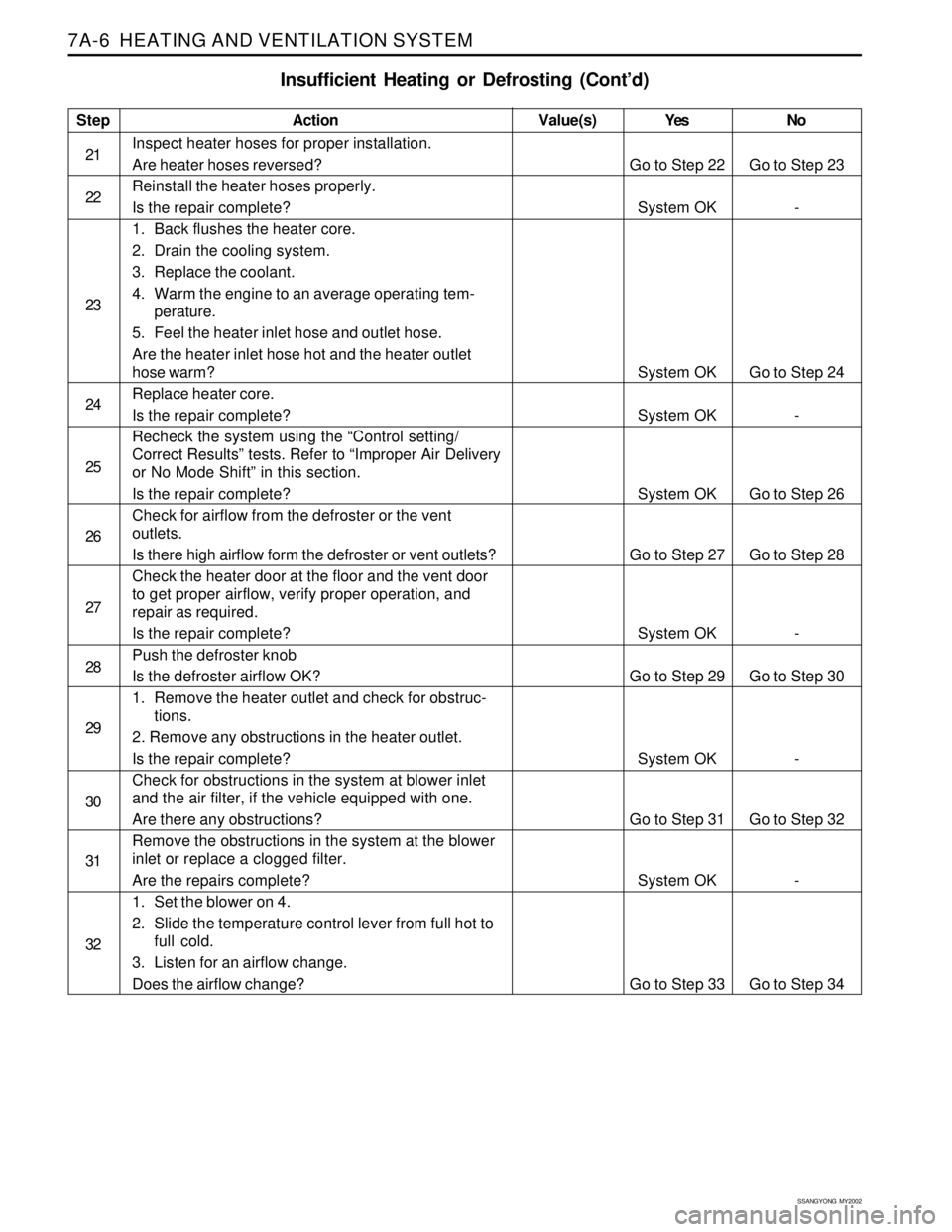
Insufficient Heating or Defrosting (Cont’d)
Step
21
22
23
24
25
26
27
28
29
30
31
32Action
Inspect heater hoses for proper installation.
Are heater hoses reversed?
Reinstall the heater hoses properly.
Is the repair complete?
1. Back flushes the heater core.
2. Drain the cooling system.
3. Replace the coolant.
4. Warm the engine to an average operating tem-
perature.
5. Feel the heater inlet hose and outlet hose.
Are the heater inlet hose hot and the heater outlet
hose warm?
Replace heater core.
Is the repair complete?
Recheck the system using the “Control setting/
Correct Results” tests. Refer to “Improper Air Delivery
or No Mode Shift” in this section.
Is the repair complete?
Check for airflow from the defroster or the vent
outlets.
Is there high airflow form the defroster or vent outlets?
Check the heater door at the floor and the vent door
to get proper airflow, verify proper operation, and
repair as required.
Is the repair complete?
Push the defroster knob
Is the defroster airflow OK?
1. Remove the heater outlet and check for obstruc-
tions.
2. Remove any obstructions in the heater outlet.
Is the repair complete?
Check for obstructions in the system at blower inlet
and the air filter, if the vehicle equipped with one.
Are there any obstructions?
Remove the obstructions in the system at the blower
inlet or replace a clogged filter.
Are the repairs complete?
1. Set the blower on 4.
2. Slide the temperature control lever from full hot to
full cold.
3. Listen for an airflow change.
Does the airflow change?Yes
Go to Step 22
System OK
System OK
System OK
System OK
Go to Step 27
System OK
Go to Step 29
System OK
Go to Step 31
System OK
Go to Step 33No
Go to Step 23
-
Go to Step 24
-
Go to Step 26
Go to Step 28
-
Go to Step 30
-
Go to Step 32
-
Go to Step 34 Value(s)
Page 1525 of 2053
SSANGYONG MY2002
7A-24 HEATING AND VENTILATION SYSTEM
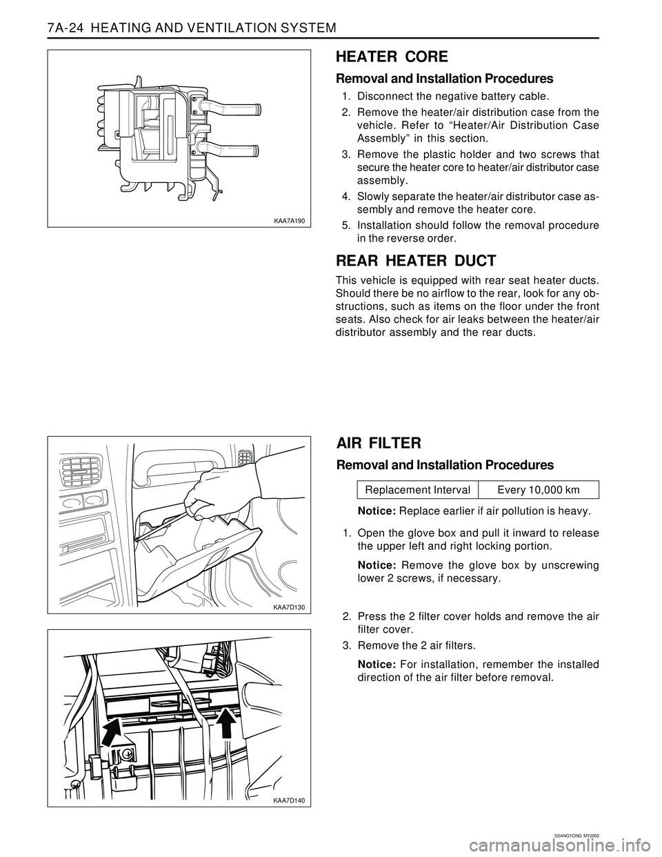
HEATER CORE
Removal and Installation Procedures
1. Disconnect the negative battery cable.
2. Remove the heater/air distribution case from the
vehicle. Refer to “Heater/Air Distribution Case
Assembly” in this section.
3. Remove the plastic holder and two screws that
secure the heater core to heater/air distributor case
assembly.
4. Slowly separate the heater/air distributor case as-
sembly and remove the heater core.
5. Installation should follow the removal procedure
in the reverse order.
REAR HEATER DUCT
This vehicle is equipped with rear seat heater ducts.
Should there be no airflow to the rear, look for any ob-
structions, such as items on the floor under the front
seats. Also check for air leaks between the heater/air
distributor assembly and the rear ducts.
KAA7A190
KAA7D130
KAA7D140
AIR FILTER
Removal and Installation Procedures
Notice: Replace earlier if air pollution is heavy.
1. Open the glove box and pull it inward to release
the upper left and right locking portion.
Notice: Remove the glove box by unscrewing
lower 2 screws, if necessary.
2. Press the 2 filter cover holds and remove the air
filter cover.
3. Remove the 2 air filters.
Notice: For installation, remember the installed
direction of the air filter before removal.
Replacement Interval Every 10,000 km
Page 1530 of 2053
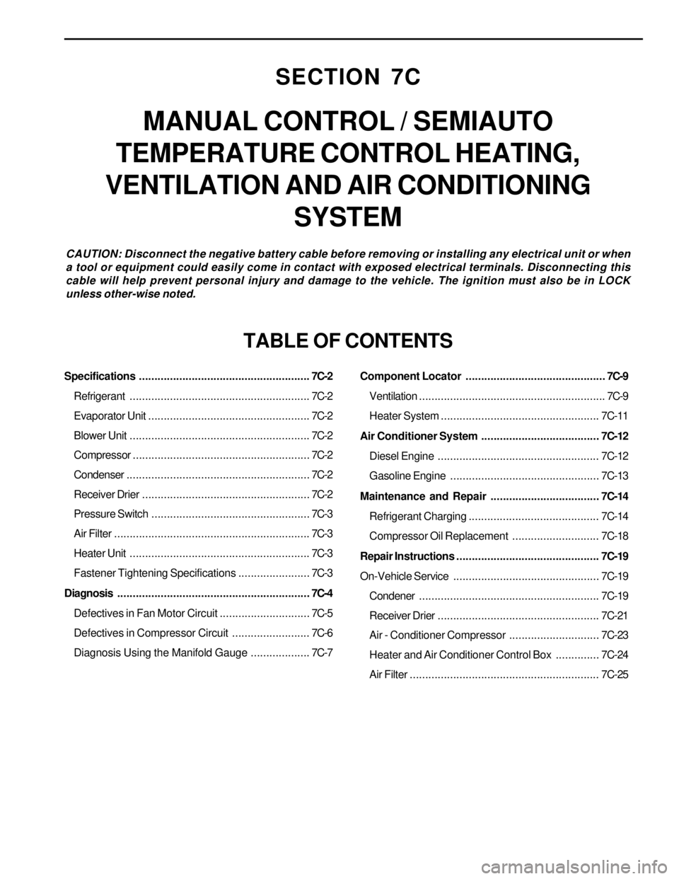
SECTION 7C
MANUAL CONTROL / SEMIAUTO
TEMPERATURE CONTROL HEATING,
VENTILATION AND AIR CONDITIONING
SYSTEM
CAUTION: Disconnect the negative battery cable before removing or installing any electrical unit or when
a tool or equipment could easily come in contact with exposed electrical terminals. Disconnecting this
cable will help prevent personal injury and damage to the vehicle. The ignition must also be in LOCK
unless other-wise noted.
TABLE OF CONTENTS
Specifications.......................................................7C-2
Refrigerant..........................................................7C-2
Evaporator Unit....................................................7C-2
Blower Unit..........................................................7C-2
Compressor.........................................................7C-2
Condenser...........................................................7C-2
Receiver Drier......................................................7C-2
Pressure Switch...................................................7C-3
Air Filter...............................................................7C-3
Heater Unit..........................................................7C-3
Fastener Tightening Specifications.......................7C-3
Diagnosis..............................................................7C-4
Defectives in Fan Motor Circuit.............................7C-5
Defectives in Compressor Circuit.........................7C-6
Diagnosis Using the Manifold Gauge...................7C-7Component Locator.............................................7C-9
Ventilation............................................................7C-9
Heater System ................................................... 7C-11
Air Conditioner System...................................... 7C-12
Diesel Engine .................................................... 7C-12
Gasoline Engine................................................ 7C-13
Maintenance and Repair................................... 7C-14
Refrigerant Charging .......................................... 7C-14
Compressor Oil Replacement............................ 7C-18
Repair Instructions.............................................. 7C-19
On-Vehicle Service............................................... 7C-19
Condener.......................................................... 7C-19
Receiver Drier.................................................... 7C-21
Air - Conditioner Compressor............................. 7C-23
Heater and Air Conditioner Control Box.............. 7C-24
Air Filter............................................................. 7C-25
Page 1532 of 2053

MANUAL & SEMIAUTO-HVAC 7C-3
SSANGYONG MY2002
PRESSURE SWITCH
Type
High (OFF)
Low (ON)ApplicationDescriptionDirect
OFF : 32 ± 2 Kgf/cm
2, DIFF : 6 ± 2 Kgf/cm2
OFF : 2.0 ± 0.2 Kgf/cm2, ON : 2.1 ± 0.2 Kgf/cm2
AIR FILTER
ReplacementApplicationDescriptionEvery 12,000 km (replace earlier if air pollution is heavy)
HEATER UNIT
Heater Core Type
Heating Capacity
Heater Core Size (L x W x T)ApplicationDescription2-ROW
4,600 Kcal/h (AT 300 CMH)
219.5 x 151.8 x 52
FASTENER TIGHTENING SPECIFICATIONS
N•m
4 - 6
4 - 6
4 - 6
5 - 8
4 - 6
20 - 30
20 - 26Lb-Ft
2.9 - 4.4
2.9 - 4.4
2.9 - 4.4
3.7 - 5.9
2.9 - 4.4
14.7 - 22.1
14.7 - 19.1 Condenser Bolt
Condenser Fan Nut
Condenser Bolt
Receiver Drier Pipe Bolt
Receiver Drier Pipe Bolt (Condenser)
Pressure Pipe Bolt
Pressure Mounting BoltLb-In
35.4 - 53.1
35.4 - 53.1
35.4 - 53.1
44.2 - 70.8
35.4 - 53.1
177.0 - 265.5
177.0 - 230.1Application