Page 157 of 2053
M162 ENGINE ELECTRICAL 1E 1 -- 5
D AEW OO M Y_2000
BATTERY
1 Cable Terminal ( -- )
2 Cable Terminal Cap ( -- )
3 Cable Terminal Cap (+)
4Nut
5 Fuseblink Box
6 Terminal (+)7 Battery holddown Bracket
8 Battery Clamp Bolt
9 Battery
10 Sub Tray
11 Battery Tray
Removal & Installation Procedure
Notice
DDisconnect the battery negative cable first.
DInsert the clamp bolt (8) into the battery tray hole (11)
from inside when installing.
Page 207 of 2053
1F1 -- 44 M162 ENGINE CONTROLS
D AEW OO M Y_2000
Measure the Fuel Delivery from the Fuel Pump
1. Disconnect the return pipe from fuel distributor and insert the appropriate hose into it.
2. Place the hose end into the beaker with the minimum capacity of 1 Liter
3. Turn the ignition switch to “ON” position.
4. Connect the terminal No. 33 and No. 5 of ECM with a service wire.
5. Measure the fuel delivery from the fuel pump
Specified Value
1 Liter/max. 35 sec.
Notice:Check the fuel filter and fuel line when the fuel delivery is not within specified value.
Measure the Current Consumption of Fuel Pump
1. Remove the fuel pump relay from fuse and relay box in trunk, and turn the ignition switch to “ON” position.
2. Using a multimeter, measure the current consumption by connecting the terminal No. 30 and No. 87 of the fuel
pump relay connector.
Specified Value
5~9A
Notice:Replace the fuel pump relay if the measured value is over 9 A.
Page 416 of 2053
M161 ENGINE ELECTRICAL 1E 2 -- 5
D AEW OO M Y_2000
BATTERY
1 Cable Terminal ( -- )
2 Cable Terminal Cap ( -- )
3 Cable Terminal Cap (+)
4Nut
5 Fuseblink Box
6 Terminal (+)7 Battery holddown Bracket
8 Battery Clamp Bolt
9 Battery
10 Sub Tray
11 Battery Tray
Removal & Installation Procedure
Notice
DDisconnect the battery negative cable first.
DInsert the clamp bolt (8) into the battery tray hole (11)
from inside when installing.
Page 462 of 2053
1F2 -- 44 M161 ENGINE CONTROLS
D AEW OO M Y_2000
Measure the Fuel Delivery from the Fuel Pump
1. Disconnect the return pipe from fuel distributor and insert the appropriate hose into it.
2. Place the hose end into the beaker with the minimum capacity of 1 Liter
3. Turn the ignition switch to “ON” position.
4. Connect the terminal No. 33 and No. 5 of ECM with a service wire.
5. Measure the fuel delivery from the fuel pump
Specified Value
1 Liter/max. 35 sec.
Notice:Check the fuel filter and fuel line when the fuel delivery is not within specified value.
Measure the Current Consumption of Fuel Pump
1. Remove the fuel pump relay from fuse and relay box in trunk, and turn the ignition switch to “ON” position.
2. Using a multimeter, measure the current consumption by connecting the terminal No. 30 and No. 87 of the fuel
pump relay connector.
Specified Value
5~9A
Notice:Replace the fuel pump relay if the measured value is over 9 A.
Page 1575 of 2053

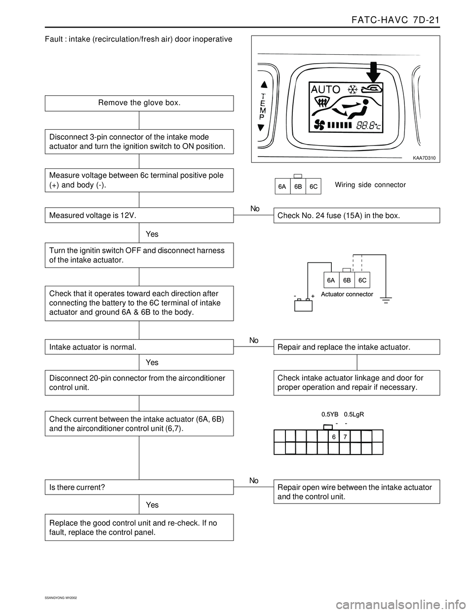
FATC-HAVC 7D-21
SSANGYONG MY2002
KAA7D310
Fault : intake (recirculation/fresh air) door inoperative
Remove the glove box.
Check No. 24 fuse (15A) in the box.
YesNo
Check that it operates toward each direction after
connecting the battery to the 6C terminal of intake
actuator and ground 6A & 6B to the body.
Wiring side connector
Intake actuator is normal.
YesRepair and replace the intake actuator. No
Check intake actuator linkage and door for
proper operation and repair if necessary.Disconnect 20-pin connector from the airconditioner
control unit.
Check current between the intake actuator (6A, 6B)
and the airconditioner control unit (6,7).
Is there current?
YesRepair open wire between the intake actuator
and the control unit. No
Replace the good control unit and re-check. If no
fault, replace the control panel.
Measure voltage between 6c terminal positive pole
(+) and body (-).
Measured voltage is 12V.
Turn the ignitin switch OFF and disconnect harness
of the intake actuator.
Disconnect 3-pin connector of the intake mode
actuator and turn the ignition switch to ON position.
Page 1576 of 2053

SSANGYONG MY2002
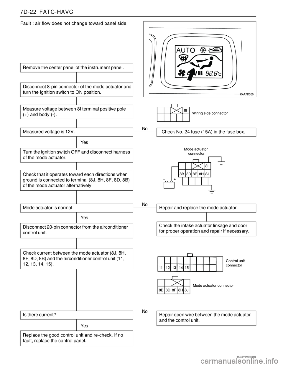
7D-22 FATC-HAVC
Fault : air flow does not change toward panel side.
Remove the center panel of the instrument panel.
Measure voltage between 8I terminal positive pole
(+) and body (-).
Measured voltage is 12V.Check No. 24 fuse (15A) in the fuse box.
Turn the ignition switch OFF and disconnect harness
of the mode actuator.YesNo
Disconnect 8-pin connector of the mode actuator and
turn the ignition switch to ON position.
Check that it operates toward each directions when
ground is connected to terminal (8J, 8H, 8F, 8D, 8B)
of the mode actuator alternatively.
Mode actuator is normal.
YesRepair and replace the mode actuator. No
Check the intake actuator linkage and door
for proper operation and repair if necessary.Disconnect 20-pin connector from the airconditioner
control unit.
Check current between the mode actuator (8J, 8H,
8F, 8D, 8B) and the airconditioner control unit (11,
12, 13, 14, 15).
Is there current?
YesRepair open wire between the mode actuator
and the control unit. No
Replace the good control unit and re-check. If no
fault, replace the control panel.
KAA7D350
Page 1644 of 2053

SSANGYONG MY2002
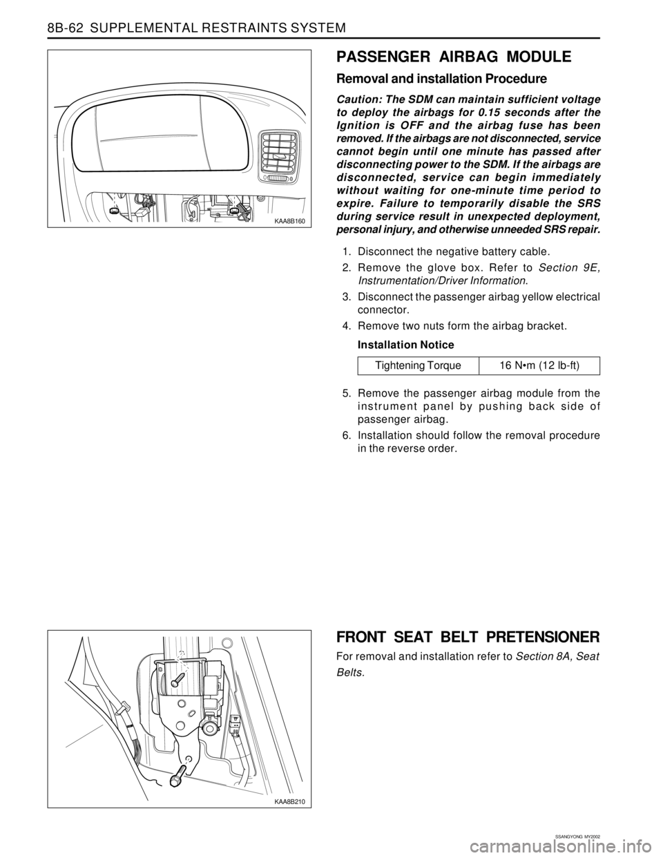
8B-62 SUPPLEMENTAL RESTRAINTS SYSTEM
KAA8B160
PASSENGER AIRBAG MODULE
Removal and installation Procedure
Caution: The SDM can maintain sufficient voltage
to deploy the airbags for 0.15 seconds after the
Ignition is OFF and the airbag fuse has been
removed. If the airbags are not disconnected, service
cannot begin until one minute has passed after
disconnecting power to the SDM. If the airbags are
disconnected, service can begin immediately
without waiting for one-minute time period to
expire. Failure to temporarily disable the SRS
during service result in unexpected deployment,
personal injury, and otherwise unneeded SRS repair.
1. Disconnect the negative battery cable.
2. Remove the glove box. Refer to Section 9E,
Instrumentation/Driver Information.
3. Disconnect the passenger airbag yellow electrical
connector.
4. Remove two nuts form the airbag bracket.
Installation Notice
5. Remove the passenger airbag module from the
instrument panel by pushing back side of
passenger airbag.
6. Installation should follow the removal procedure
in the reverse order.
Tightening Torque 16 Nm (12 lb-ft)
FRONT SEAT BELT PRETENSIONER
For removal and installation refer to Section 8A, Seat
Belts.
KAA8B210
Page 1652 of 2053

SECTION 9A
BODY WIRING SYSTEM
CAUTION: Disconnect the negative battery cable before removing or installing any electrical unit or when a
tool or equipment could easily come in contact with exposed electrical terminals. Disconnecting this cable
will help prevent personal injury and damage to the vehicle. The ignition must also be in LOCK unless
otherwise noted.
TABLE OF CONTENTS
General Description.............................................9A-2
Wire Color Chart..................................................9A-2
Engine Room Fuse & Relay Box......................... 9A-3
Usage of Fuse in Engine Room Fuse Box.............9A-5
Passenger Room Fuse Box..................................9A-6
Usage of Fuse in Engine Room Fuse Box.............9A-7
Schematic and Routing Diagrams.......................9A-8
Engine Room Fuse & Relay Circuit.......................9A-8
Wiring Harness & Connector &
Ground Location................................................. 9A-11
W/H Engine Room.............................................9A-11W/H Main..........................................................9A-12
W/H Main (Floor)............................................... 9A-14
W/H Roof..........................................................9A-15
W/H Seat Heater................................................9A-16
W/H Door..........................................................9A-17
W/H Tail Gate....................................................9A-18
W/H Air-Conditioner...........................................9A-19
W/H Engine Control (Gasoline)...........................9A-20
W/H Pre-Heating (Diesel)...................................9A-21
W/H Transmission..............................................9A-22