1997 SSANGYONG KORANDO oil
[x] Cancel search: oilPage 1442 of 2053
TRANSFER CASE (PART TIME - 4408) 5D2-43
SSANGYONG MY2002
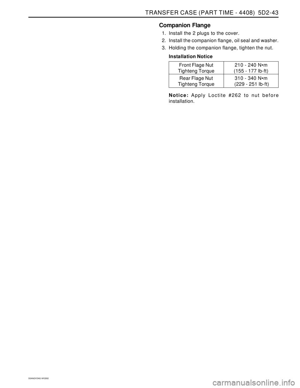
Companion Flange
1. Install the 2 plugs to the cover.
2. Install the companion flange, oil seal and washer.
3. Holding the companion flange, tighten the nut.
Installation Notice
Notice: Apply Loctite #262 to nut before
installation.210 - 240 Nm
(155 - 177 lb-ft)
310 - 340 Nm
(229 - 251 lb-ft)
Front Flage Nut
Tighteng Torque
Rear Flage Nut
Tighteng Torque
Page 1446 of 2053
SSANGYONG MY2002
6A-4 POWER STEERING SYSTEM
KAA6A020
DIAGNOSTIC INFORMATION AND PROCEDURES
POWER STEERING SYSTEM
PRESSURE TEST
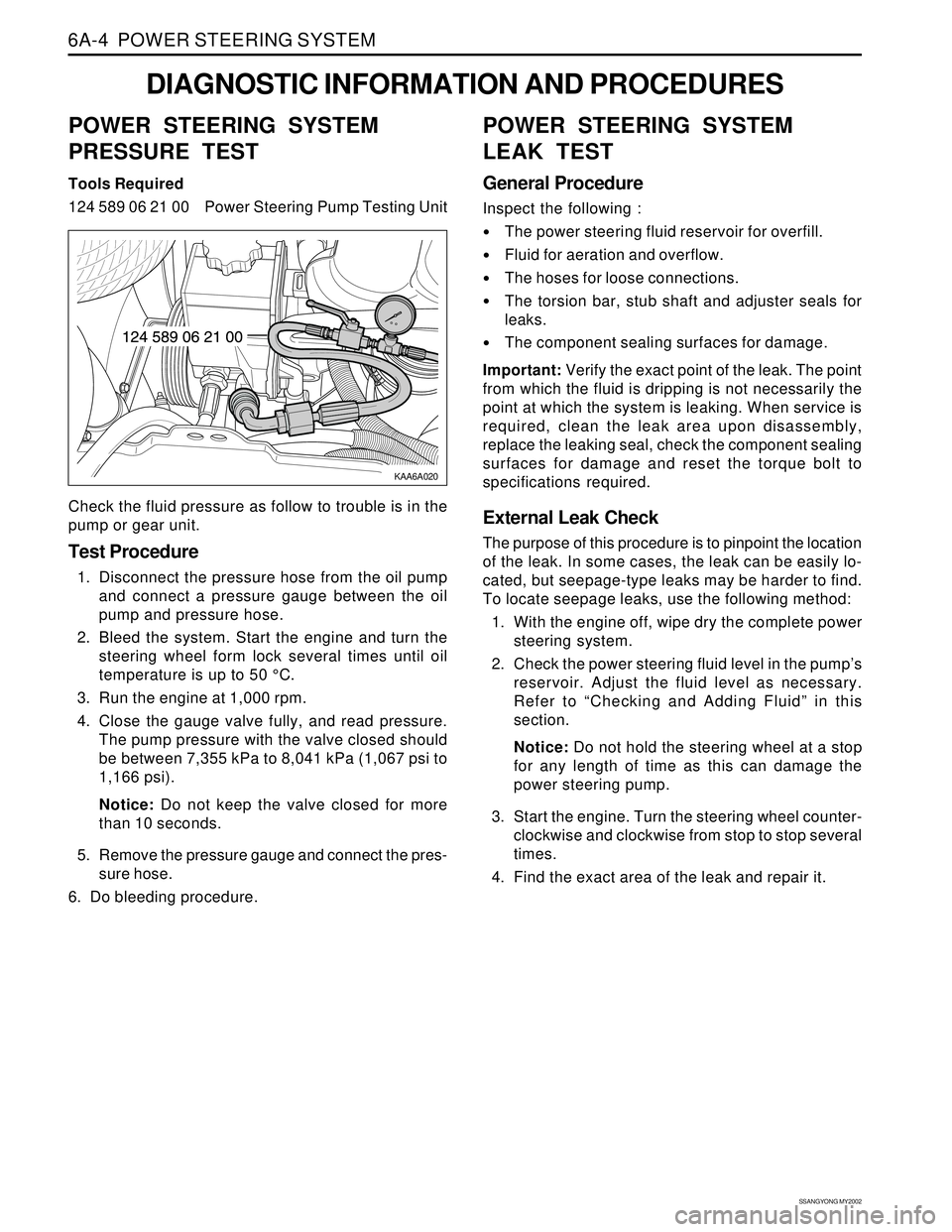
Tools Required
124 589 06 21 00 Power Steering Pump Testing Unit
Check the fluid pressure as follow to trouble is in the
pump or gear unit.
Test Procedure
1. Disconnect the pressure hose from the oil pump
and connect a pressure gauge between the oil
pump and pressure hose.
2. Bleed the system. Start the engine and turn the
steering wheel form lock several times until oil
temperature is up to 50 °C.
3. Run the engine at 1,000 rpm.
4. Close the gauge valve fully, and read pressure.
The pump pressure with the valve closed should
be between 7,355 kPa to 8,041 kPa (1,067 psi to
1,166 psi).
Notice: Do not keep the valve closed for more
than 10 seconds.
5. Remove the pressure gauge and connect the pres-
sure hose.
6. Do bleeding procedure.
POWER STEERING SYSTEM
LEAK TEST
General Procedure
Inspect the following :
The power steering fluid reservoir for overfill.
Fluid for aeration and overflow.
The hoses for loose connections.
The torsion bar, stub shaft and adjuster seals for
leaks.
The component sealing surfaces for damage.
Important: Verify the exact point of the leak. The point
from which the fluid is dripping is not necessarily the
point at which the system is leaking. When service is
required, clean the leak area upon disassembly,
replace the leaking seal, check the component sealing
surfaces for damage and reset the torque bolt to
specifications required.
External Leak Check
The purpose of this procedure is to pinpoint the location
of the leak. In some cases, the leak can be easily lo-
cated, but seepage-type leaks may be harder to find.
To locate seepage leaks, use the following method:
1. With the engine off, wipe dry the complete power
steering system.
2. Check the power steering fluid level in the pump’s
reservoir. Adjust the fluid level as necessary.
Refer to “Checking and Adding Fluid” in this
section.
Notice: Do not hold the steering wheel at a stop
for any length of time as this can damage the
power steering pump.
3. Start the engine. Turn the steering wheel counter-
clockwise and clockwise from stop to stop several
times.
4. Find the exact area of the leak and repair it.
Page 1447 of 2053

POWER STEERING SYSTEM 6A-5
SSANGYONG MY2002
BLEEDING THE POWER
STEERING SYSTEM
1. Disconnect the fuel line. Using a starter motor,
crank the engine and turn the steering wheel from
lock to start 5 or 6 times.
Notice: Do bleeding with engine cranking. If bleed
with idling, there can be a air contact with oil.
2. Connect the fuel feed line and start the engine at
idle speed.
3. Turn the steering wheel from lock to lock until there
is no more air in oil reservoir.
4. Connect the oil level is within specification.
5. By turning the steering wheel left to right, check
the oil level change.
Notice: If oil is not changes more than 5 mm, do
bleeding again. If oil level rises suddenly when
stopped engine, again.
MAINTENANCE
CHECKING AND ADDING FLUID
Notice: When adding fluid or making a complete fluid
change, always use DEXRON. - II power steering fluid.
Failure to use the proper fluid will cause hose and seal
damage and fluid leaks.
1. The power steering fluid level is indicated by marks
on a fluid level indicator on the fluid reservoir cap.
2. If the fluid is warmed up to 66 °C (150 °F), the fluid
level should be between the MAX and MIN marks.
Add fluid as needed.
3. If the fluid is cool, 21 °C (70 °F), the fluid level should
be at the MIN mark. Add fluid as needed.
Page 1455 of 2053
SSANGYONG MY2002
6A-4 POWER STEERING SYSTEM
KAA6A020
DIAGNOSTIC INFORMATION AND PROCEDURES
POWER STEERING SYSTEM
PRESSURE TEST
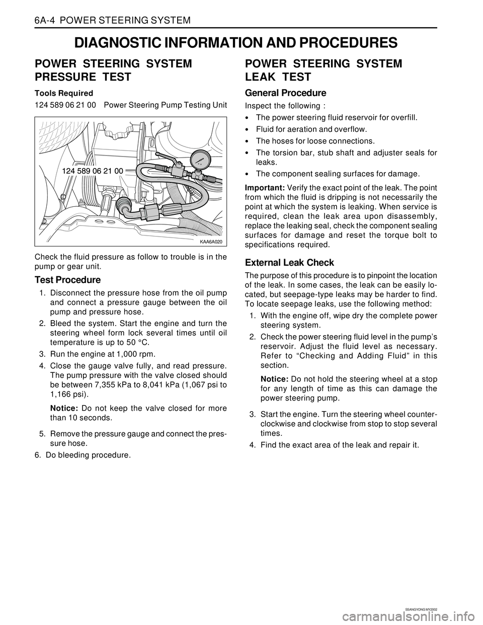
Tools Required
124 589 06 21 00 Power Steering Pump Testing Unit
Check the fluid pressure as follow to trouble is in the
pump or gear unit.
Test Procedure
1. Disconnect the pressure hose from the oil pump
and connect a pressure gauge between the oil
pump and pressure hose.
2. Bleed the system. Start the engine and turn the
steering wheel form lock several times until oil
temperature is up to 50 °C.
3. Run the engine at 1,000 rpm.
4. Close the gauge valve fully, and read pressure.
The pump pressure with the valve closed should
be between 7,355 kPa to 8,041 kPa (1,067 psi to
1,166 psi).
Notice: Do not keep the valve closed for more
than 10 seconds.
5. Remove the pressure gauge and connect the pres-
sure hose.
6. Do bleeding procedure.
POWER STEERING SYSTEM
LEAK TEST
General Procedure
Inspect the following :
The power steering fluid reservoir for overfill.
Fluid for aeration and overflow.
The hoses for loose connections.
The torsion bar, stub shaft and adjuster seals for
leaks.
The component sealing surfaces for damage.
Important: Verify the exact point of the leak. The point
from which the fluid is dripping is not necessarily the
point at which the system is leaking. When service is
required, clean the leak area upon disassembly,
replace the leaking seal, check the component sealing
surfaces for damage and reset the torque bolt to
specifications required.
External Leak Check
The purpose of this procedure is to pinpoint the location
of the leak. In some cases, the leak can be easily lo-
cated, but seepage-type leaks may be harder to find.
To locate seepage leaks, use the following method:
1. With the engine off, wipe dry the complete power
steering system.
2. Check the power steering fluid level in the pump’s
reservoir. Adjust the fluid level as necessary.
Refer to “Checking and Adding Fluid” in this
section.
Notice: Do not hold the steering wheel at a stop
for any length of time as this can damage the
power steering pump.
3. Start the engine. Turn the steering wheel counter-
clockwise and clockwise from stop to stop several
times.
4. Find the exact area of the leak and repair it.
Page 1456 of 2053
POWER STEERING SYSTEM 6A-5
SSANGYONG MY2002
BLEEDING THE POWER
STEERING SYSTEM
1. Disconnect the fuel line. Using a starter motor,
crank the engine and turn the steering wheel from
lock to start 5 or 6 times.
Notice: Do bleeding with engine cranking. If bleed
with idling, there can be a air contact with oil.
2. Connect the fuel feed line and start the engine at
idle speed.
3. Turn the steering wheel from lock to lock until there
is no more air in oil reservoir.
4. Connect the oil level is within specification.
5. By turning the steering wheel left to right, check
the oil level change.
Notice: If oil is not changes more than 5 mm, do
bleeding again. If oil level rises suddenly when
stopped engine, again.
MAINTENANCE
CHECKING AND ADDING FLUID
Notice: When adding fluid or making a complete fluid
change, always use DEXRON. - II power steering fluid.
Failure to use the proper fluid will cause hose and seal
damage and fluid leaks.
1. The power steering fluid level is indicated by marks
on a fluid level indicator on the fluid reservoir cap.
2. If the fluid is warmed up to 66 °C (150 °F), the fluid
level should be between the MAX and MIN marks.
Add fluid as needed.
3. If the fluid is cool, 21 °C (70 °F), the fluid level should
be at the MIN mark. Add fluid as needed.
Page 1463 of 2053
SSANGYONG MY2002
6B-2 POWER STEERING PUMP
DESCRIPTION AND OPERATION
GENERAL DESCRIPTION
The power steering pump is a multivaned hydraulic
pump. The serpentine accessory drive belt on the en-
gine drives the power steering pump. The power steer-
ing pump provides the hydraulic pressure to the power
steering gear.
The power steering gear uses the hydraulic pressure
to assist in steering the vehicle.
When steering conditions exceed maximum pressure
requirements, such as when the wheels are turned
against the stops, the pressure built up in the steeringgear exerts pressure on the spring end of the flow
control valve. The high pressure lifts the relief valve
ball from its seat and allows oil to flow through a trigger
orifice located in the outlet fitting. This reduce pressure
on the spring end of the flow control valve which then
opens and allows the oil to return to the intake side of
the pump. This action limits maximum pressure output
of the pump to a safe level.
No repair procedures are to be done on the internal
components of the power steering pump. The only ser-
viceable components of the power steering pump are
the power steering pump pulley and the pump itself.
Page 1530 of 2053
SECTION 7C
MANUAL CONTROL / SEMIAUTO
TEMPERATURE CONTROL HEATING,
VENTILATION AND AIR CONDITIONING
SYSTEM
CAUTION: Disconnect the negative battery cable before removing or installing any electrical unit or when
a tool or equipment could easily come in contact with exposed electrical terminals. Disconnecting this
cable will help prevent personal injury and damage to the vehicle. The ignition must also be in LOCK
unless other-wise noted.
TABLE OF CONTENTS
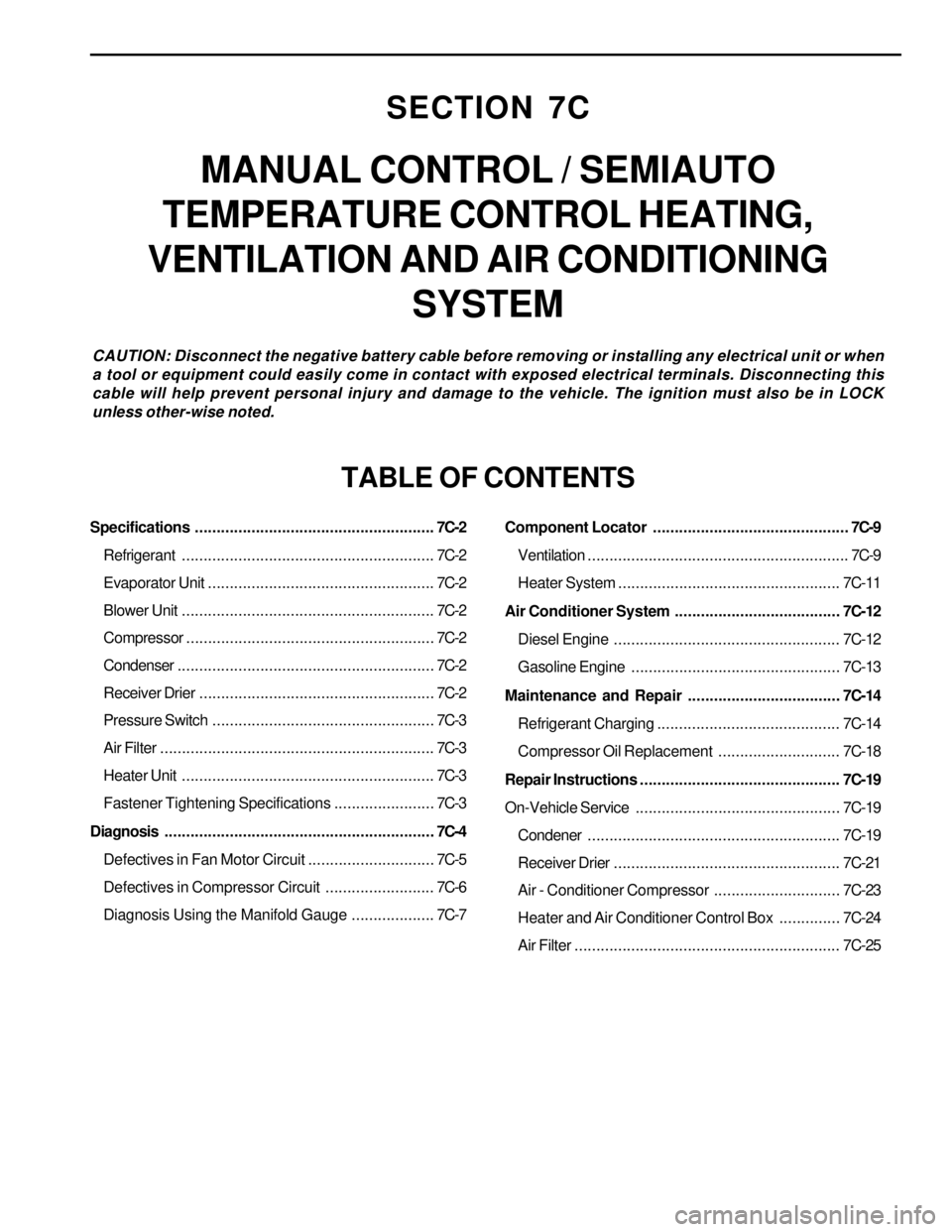
Specifications.......................................................7C-2
Refrigerant..........................................................7C-2
Evaporator Unit....................................................7C-2
Blower Unit..........................................................7C-2
Compressor.........................................................7C-2
Condenser...........................................................7C-2
Receiver Drier......................................................7C-2
Pressure Switch...................................................7C-3
Air Filter...............................................................7C-3
Heater Unit..........................................................7C-3
Fastener Tightening Specifications.......................7C-3
Diagnosis..............................................................7C-4
Defectives in Fan Motor Circuit.............................7C-5
Defectives in Compressor Circuit.........................7C-6
Diagnosis Using the Manifold Gauge...................7C-7Component Locator.............................................7C-9
Ventilation............................................................7C-9
Heater System ................................................... 7C-11
Air Conditioner System...................................... 7C-12
Diesel Engine .................................................... 7C-12
Gasoline Engine................................................ 7C-13
Maintenance and Repair................................... 7C-14
Refrigerant Charging .......................................... 7C-14
Compressor Oil Replacement............................ 7C-18
Repair Instructions.............................................. 7C-19
On-Vehicle Service............................................... 7C-19
Condener.......................................................... 7C-19
Receiver Drier.................................................... 7C-21
Air - Conditioner Compressor............................. 7C-23
Heater and Air Conditioner Control Box.............. 7C-24
Air Filter............................................................. 7C-25
Page 1531 of 2053
SSANGYONG MY2002
7C-2 MANUAL & SEMIAUTO-HVAC
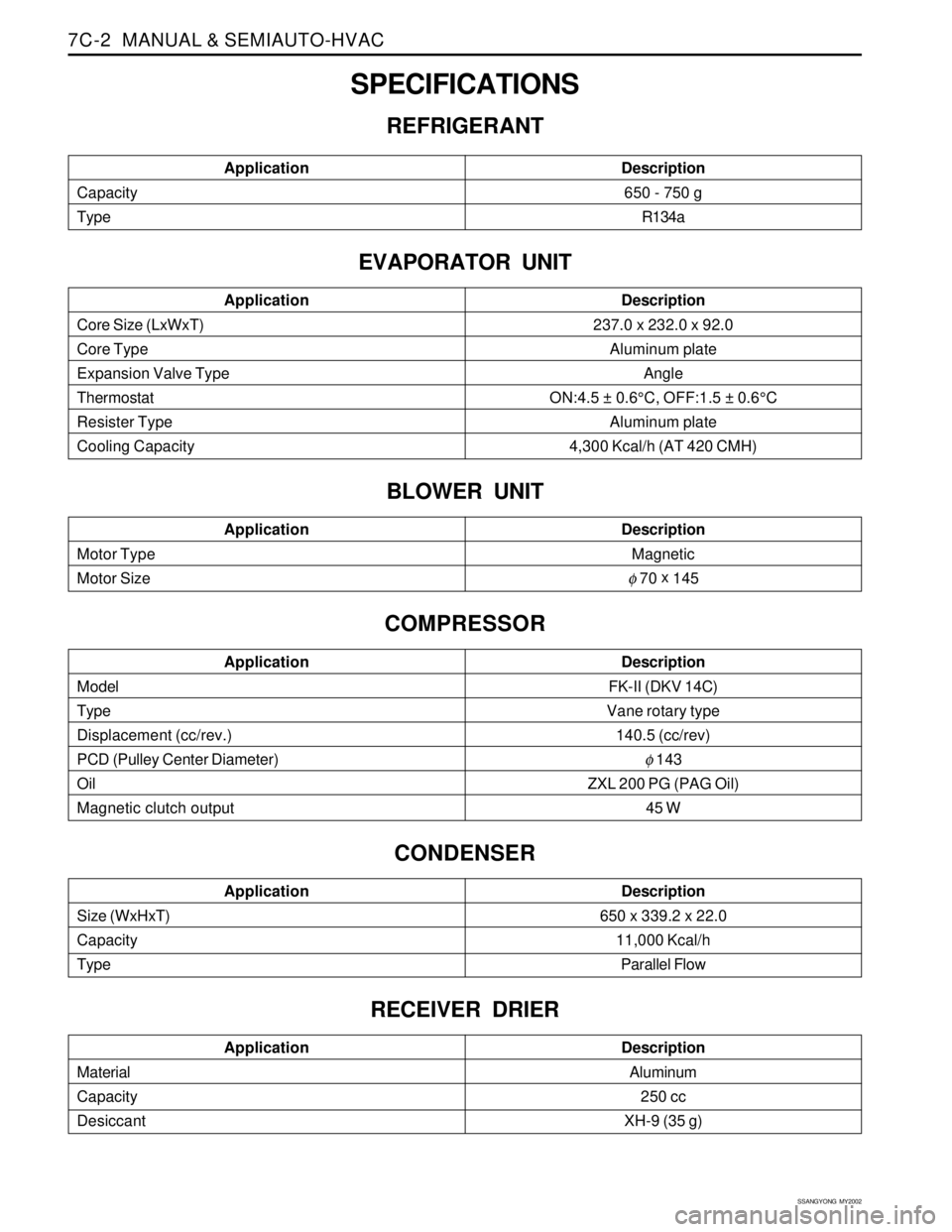
SPECIFICATIONS
REFRIGERANT
Core Size (LxWxT)
Core Type
Expansion Valve Type
Thermostat
Resister Type
Cooling CapacityApplicationDescription237.0 x 232.0 x 92.0
Aluminum plate
Angle
ON:4.5 ± 0.6°C, OFF:1.5 ± 0.6°C
Aluminum plate
4,300 Kcal/h (AT 420 CMH)
Capacity
TypeApplicationDescription650 - 750 g
R134a
EVAPORATOR UNIT
BLOWER UNIT
Motor Type
Motor SizeApplicationDescriptionMagnetic
φ 70 x
145
COMPRESSOR
Model
Type
Displacement (cc/rev.)
PCD (Pulley Center Diameter)
Oil
Magnetic clutch outputApplicationDescriptionFK-II (DKV 14C)
Vane rotary type
140.5 (cc/rev)
φ 143
ZXL 200 PG (PAG Oil)
45 W
CONDENSER
Size (WxHxT)
Capacity
TypeApplicationDescription650 x 339.2 x 22.0
11,000 Kcal/h
Parallel Flow
RECEIVER DRIER
Material
Capacity
DesiccantApplicationDescriptionAluminum
250 cc
XH-9 (35 g)