1997 SSANGYONG KORANDO oil
[x] Cancel search: oilPage 1365 of 2053

SSAMGYONG MY2002
5C-10 CLUTCH
1 Snap Pin
2 Clevis Pin
3 Clevis
4 Lock Nut
5 Flange Nut.................... 8 - 18 Nm (6 - 13 lb-ft)
6 Push Rod
7 Cylinder Body
8 Oil Pipe..................... 15 - 18 Nm (11 - 13 lb-ft)
MASTER CYLINDER
9 Clamp
10 Reservoir
11 Spring
12 Piston Assembly
13 Boot
14 Plate
15 Snap Ring
KAA5C130
Notice: Do not disassemble the No. 12.
Page 1369 of 2053
CLUTCH 5C-15
SSANGYONG MY2002
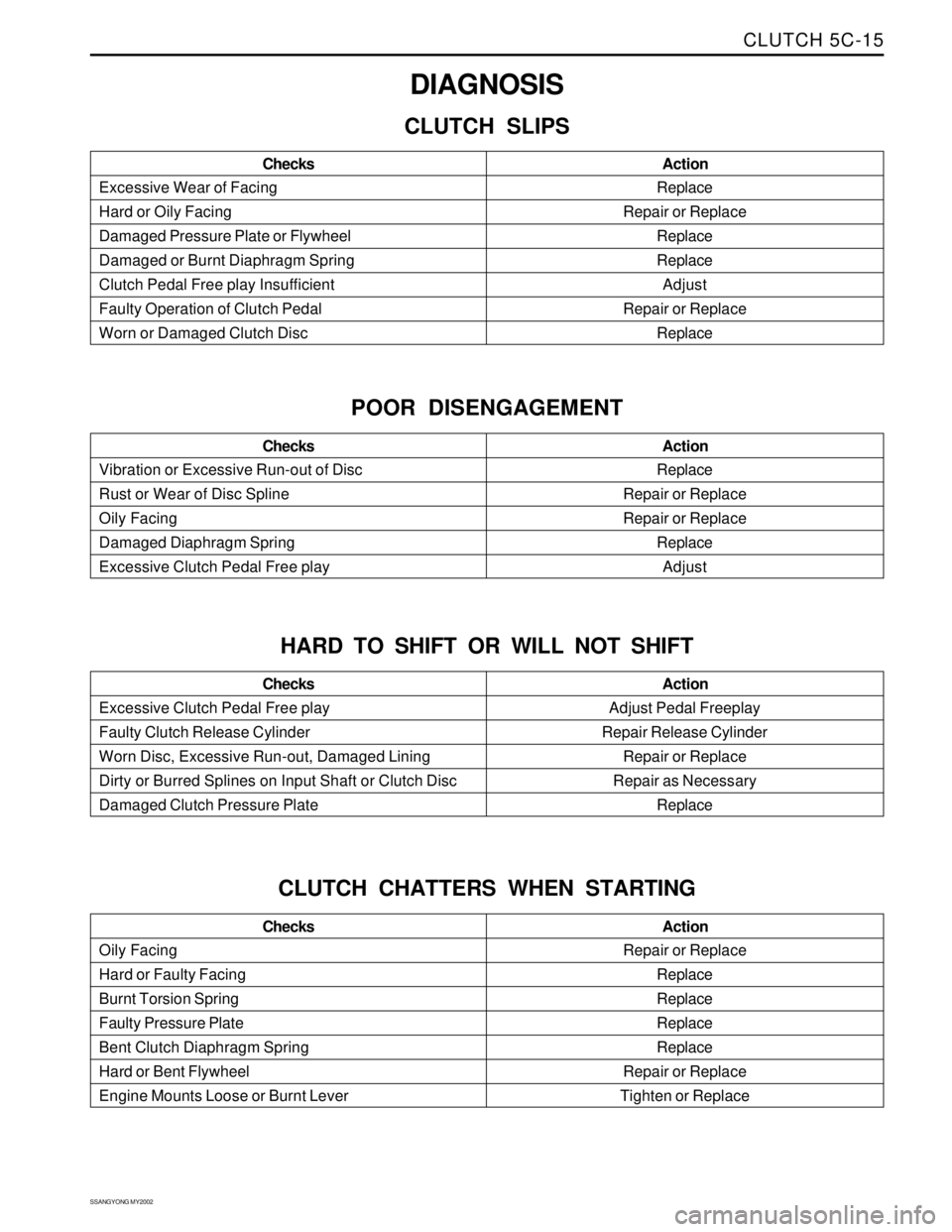
Replace
Repair or Replace
Replace
Replace
Adjust
Repair or Replace
Replace Excessive Wear of Facing
Hard or Oily Facing
Damaged Pressure Plate or Flywheel
Damaged or Burnt Diaphragm Spring
Clutch Pedal Free play Insufficient
Faulty Operation of Clutch Pedal
Worn or Damaged Clutch DiscAction Checks
DIAGNOSIS
CLUTCH SLIPS
Replace
Repair or Replace
Repair or Replace
Replace
Adjust Vibration or Excessive Run-out of Disc
Rust or Wear of Disc Spline
Oily Facing
Damaged Diaphragm Spring
Excessive Clutch Pedal Free playAction Checks
POOR DISENGAGEMENT
Adjust Pedal Freeplay
Repair Release Cylinder
Repair or Replace
Repair as Necessary
Replace Excessive Clutch Pedal Free play
Faulty Clutch Release Cylinder
Worn Disc, Excessive Run-out, Damaged Lining
Dirty or Burred Splines on Input Shaft or Clutch Disc
Damaged Clutch Pressure PlateAction Checks
HARD TO SHIFT OR WILL NOT SHIFT
Repair or Replace
Replace
Replace
Replace
Replace
Repair or Replace
Tighten or Replace Oily Facing
Hard or Faulty Facing
Burnt Torsion Spring
Faulty Pressure Plate
Bent Clutch Diaphragm Spring
Hard or Bent Flywheel
Engine Mounts Loose or Burnt LeverAction Checks
CLUTCH CHATTERS WHEN STARTING
Page 1372 of 2053
SECTION 5D1
TRANSFER CASE (TOD)
CAUTION: Disconnect the negative battery cable before removing or installing any electrical unit or when a
tool or equipment could easily come in contact with exposed electrical terminals. Disconnecting this cable
will help prevent personal injury and damage to the vehicle. The ignition must also be in LOCK unless
other-wise noted.
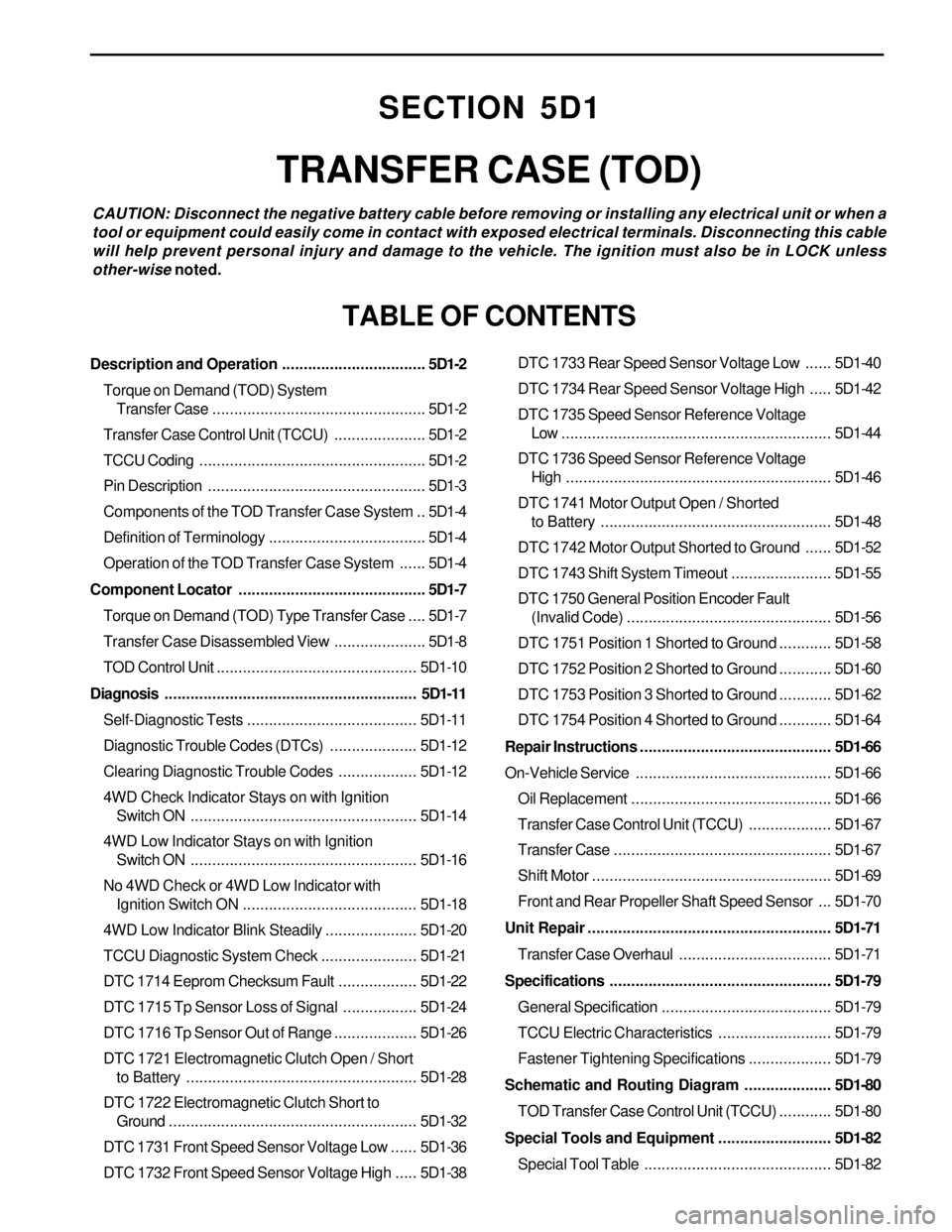
TABLE OF CONTENTS
Description and Operation.................................5D1-2
Torque on Demand (TOD) System
Transfer Case.................................................5D1-2
Transfer Case Control Unit (TCCU).....................5D1-2
TCCU Coding....................................................5D1-2
Pin Description..................................................5D1-3
Components of the TOD Transfer Case System ..5D1-4
Definition of Terminology....................................5D1-4
Operation of the TOD Transfer Case System......5D1-4
Component Locator...........................................5D1-7
Torque on Demand (TOD) Type Transfer Case....5D1-7
Transfer Case Disassembled View.....................5D1-8
TOD Control Unit..............................................5D1-10
Diagnosis..........................................................5D1-11
Self-Diagnostic Tests.......................................5D1-11
Diagnostic Trouble Codes (DTCs)....................5D1-12
Clearing Diagnostic Trouble Codes..................5D1-12
4WD Check Indicator Stays on with Ignition
Switch ON....................................................5D1-14
4WD Low Indicator Stays on with Ignition
Switch ON....................................................5D1-16
No 4WD Check or 4WD Low Indicator with
Ignition Switch ON........................................5D1-18
4WD Low Indicator Blink Steadily.....................5D1-20
TCCU Diagnostic System Check......................5D1-21
DTC 1714 Eeprom Checksum Fault..................5D1-22
DTC 1715 Tp Sensor Loss of Signal.................5D1-24
DTC 1716 Tp Sensor Out of Range...................5D1-26
DTC 1721 Electromagnetic Clutch Open / Short
to Battery.....................................................5D1-28
DTC 1722 Electromagnetic Clutch Short to
Ground.........................................................5D1-32
DTC 1731 Front Speed Sensor Voltage Low......5D1-36
DTC 1732 Front Speed Sensor Voltage High.....5D1-38DTC 1733 Rear Speed Sensor Voltage Low......5D1-40
DTC 1734 Rear Speed Sensor Voltage High.....5D1-42
DTC 1735 Speed Sensor Reference Voltage
Low ..............................................................5D1-44
DTC 1736 Speed Sensor Reference Voltage
High.............................................................5D1-46
DTC 1741 Motor Output Open / Shorted
to Battery.....................................................5D1-48
DTC 1742 Motor Output Shorted to Ground......5D1-52
DTC 1743 Shift System Timeout.......................5D1-55
DTC 1750 General Position Encoder Fault
(Invalid Code)...............................................5D1-56
DTC 1751 Position 1 Shorted to Ground............5D1-58
DTC 1752 Position 2 Shorted to Ground............5D1-60
DTC 1753 Position 3 Shorted to Ground............5D1-62
DTC 1754 Position 4 Shorted to Ground............5D1-64
Repair Instructions............................................5D1-66
On-Vehicle Service.............................................5D1-66
Oil Replacement..............................................5D1-66
Transfer Case Control Unit (TCCU)...................5D1-67
Transfer Case..................................................5D1-67
Shift Motor.......................................................5D1-69
Front and Rear Propeller Shaft Speed Sensor ...5D1-70
Unit Repair........................................................5D1-71
Transfer Case Overhaul...................................5D1-71
Specifications...................................................5D1-79
General Specification.......................................5D1-79
TCCU Electric Characteristics..........................5D1-79
Fastener Tightening Specifications...................5D1-79
Schematic and Routing Diagram....................5D1-80
TOD Transfer Case Control Unit (TCCU)............5D1-80
Special Tools and Equipment..........................5D1-82
Special Tool Table ...........................................5D1-82
Page 1379 of 2053
TRANSFER CASE 5D1-9
SSANGYONG MY2002
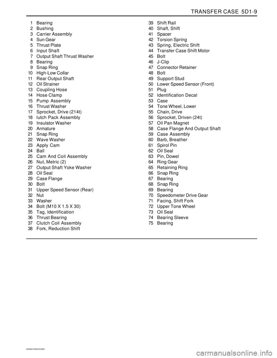
1 Bearing
2 Bushing
3 Carrier Assembly
4 Sun Gear
5 Thrust Plate
6 Input Shaft
7 Output Shaft Thrust Washer
8 Bearing
9 Snap Ring
10 High-Low Collar
11 Rear Output Shaft
12 Oil Strainer
13 Coupling Hose
14 Hose Clamp
15 Pump Assembly
16 Thrust Washer
17 Sprocket, Drive (214t)
18 lutch Pack Assembly
19 Insulator Washer
20 Armature
21 Snap Ring
22 Wave Washer
23 Apply Cam
24 Ball
25 Cam And Coil Assembly
26 Nut, Metric (2)
27 Output Shaft Yoke Washer
28 Oil Seal
29 Case Flange
30 Bolt
31 Upper Speed Sensor (Rear)
32 Nut
33 Washer
34 Bolt (M10 X 1.5 X 30)
35 Tag, Identification
36 Thrust Bearing
37 Clutch Coil Assembly
38 Fork, Reduction Shift39 Shift Rail
40 Shaft, Shift
41 Spacer
42 Torsion Spring
43 Spring, Electric Shift
44 Transfer Case Shift Motor
45 Bolt
46 J-Clip
47 Connector Retainer
48 Bolt
49 Support Stud
50 Lower Speed Sensor (Front)
51 Plug
52 Identification Decal
53 Case
54 Tone Wheel, Lower
55 Chain, Drive
56 Sprocket, Driven (24t)
57 Oil Pan Magnet
58 Case Flange And Output Shaft
59 Case Assembly
60 Barb, Breather
61 Spirol Pin
62 Oil Seal
63 Pin, Dowel
64 Ring Gear
65 Retaining Ring
66 Snap Ring
67 Bearing
68 Snap Ring
69 Bearing
70 Speedometer Drive Gear
71 Facing, Shift Fork
72 Upper Tone Wheel
73 Oil Seal
74 Bearing Sleeve
75 Bearing
Page 1388 of 2053
SSANGYONG MY2002
5D1-66 TRANSFER CASE
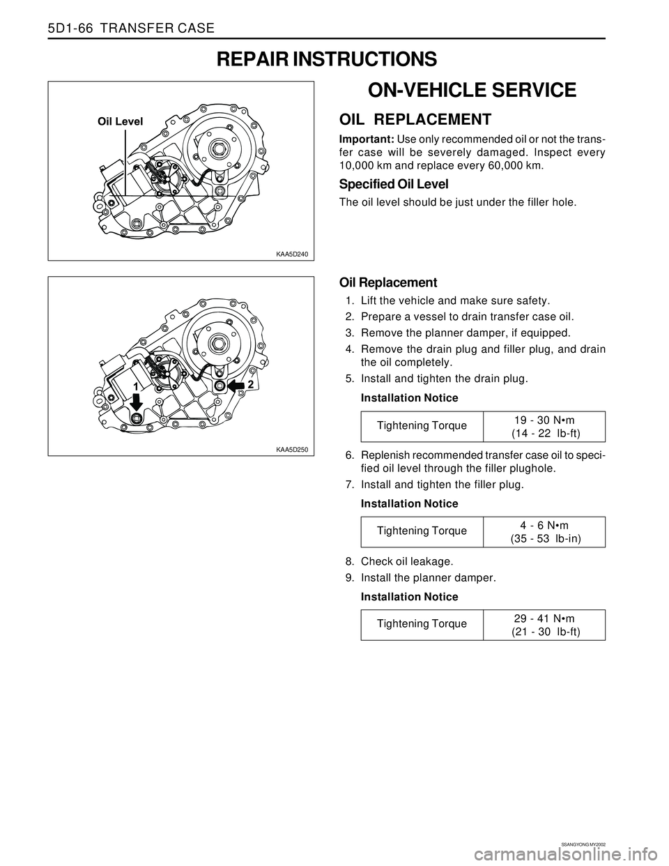
KAA5D240
KAA5D250
ON-VEHICLE SERVICE
OIL REPLACEMENT
Important: Use only recommended oil or not the trans-
fer case will be severely damaged. Inspect every
10,000 km and replace every 60,000 km.
Specified Oil Level
The oil level should be just under the filler hole.
REPAIR INSTRUCTIONS
Oil Replacement
1. Lift the vehicle and make sure safety.
2. Prepare a vessel to drain transfer case oil.
3. Remove the planner damper, if equipped.
4. Remove the drain plug and filler plug, and drain
the oil completely.
5. Install and tighten the drain plug.
Installation Notice
6. Replenish recommended transfer case oil to speci-
fied oil level through the filler plughole.
7. Install and tighten the filler plug.
Installation Notice
8. Check oil leakage.
9. Install the planner damper.
Installation Notice
Tightening Torque19 - 30 Nm
(14 - 22 lb-ft)
Tightening Torque4 - 6 Nm
(35 - 53 lb-in)
Tightening Torque29 - 41 Nm
(21 - 30 lb-ft)
Page 1389 of 2053
TRANSFER CASE 5D1-67
SSANGYONG MY2002
KAA5D260
KAA5D270
TRANSFER CASE CONTROL UNIT
(TCCU)
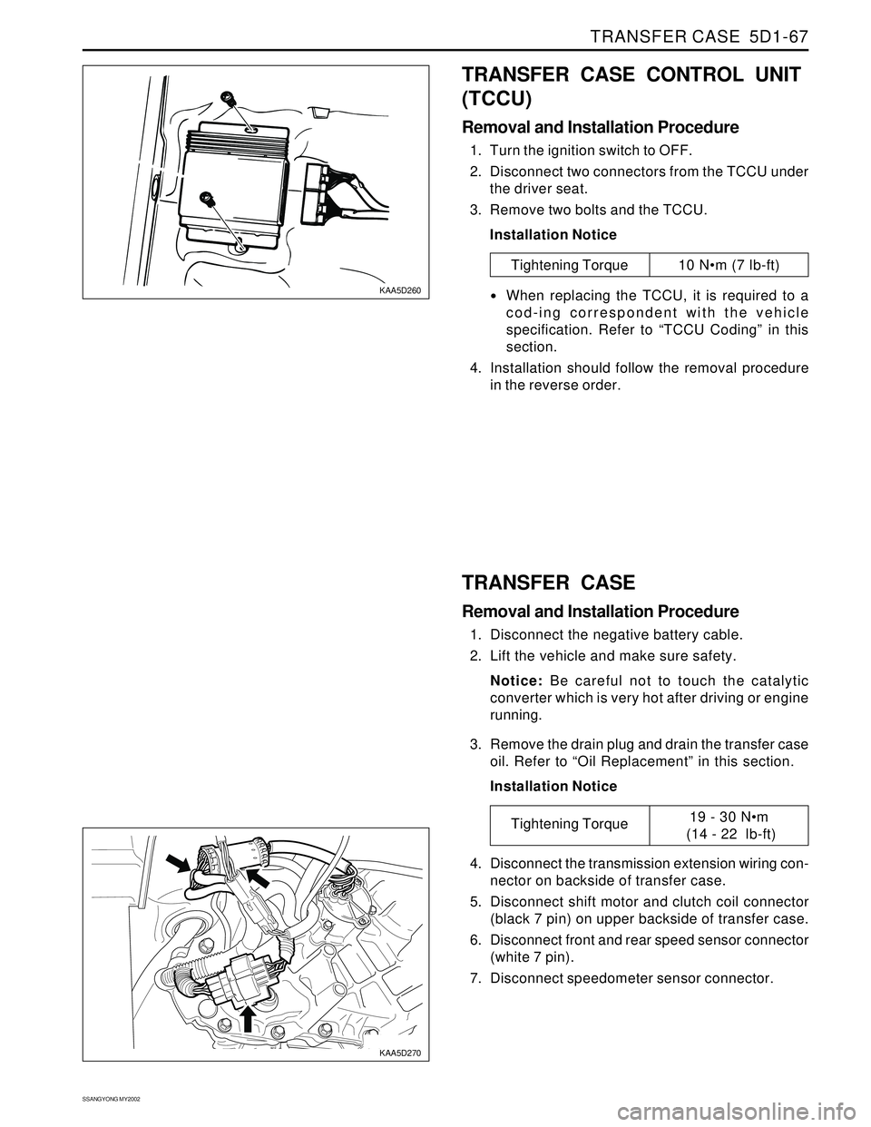
Removal and Installation Procedure
1. Turn the ignition switch to OFF.
2. Disconnect two connectors from the TCCU under
the driver seat.
3. Remove two bolts and the TCCU.
Installation Notice
Tightening Torque 10 Nm (7 lb-ft)
When replacing the TCCU, it is required to a
cod-ing correspondent with the vehicle
specification. Refer to “TCCU Coding” in this
section.
4. Installation should follow the removal procedure
in the reverse order.
TRANSFER CASE
Removal and Installation Procedure
1. Disconnect the negative battery cable.
2. Lift the vehicle and make sure safety.
Notice: Be careful not to touch the catalytic
converter which is very hot after driving or engine
running.
3. Remove the drain plug and drain the transfer case
oil. Refer to “Oil Replacement” in this section.
Installation Notice
4. Disconnect the transmission extension wiring con-
nector on backside of transfer case.
5. Disconnect shift motor and clutch coil connector
(black 7 pin) on upper backside of transfer case.
6. Disconnect front and rear speed sensor connector
(white 7 pin).
7. Disconnect speedometer sensor connector.
Tightening Torque19 - 30 Nm
(14 - 22 lb-ft)
Page 1391 of 2053
TRANSFER CASE 5D1-69
SSANGYONG MY2002
KAA5D320
KAA5D330
SHIFT MOTOR
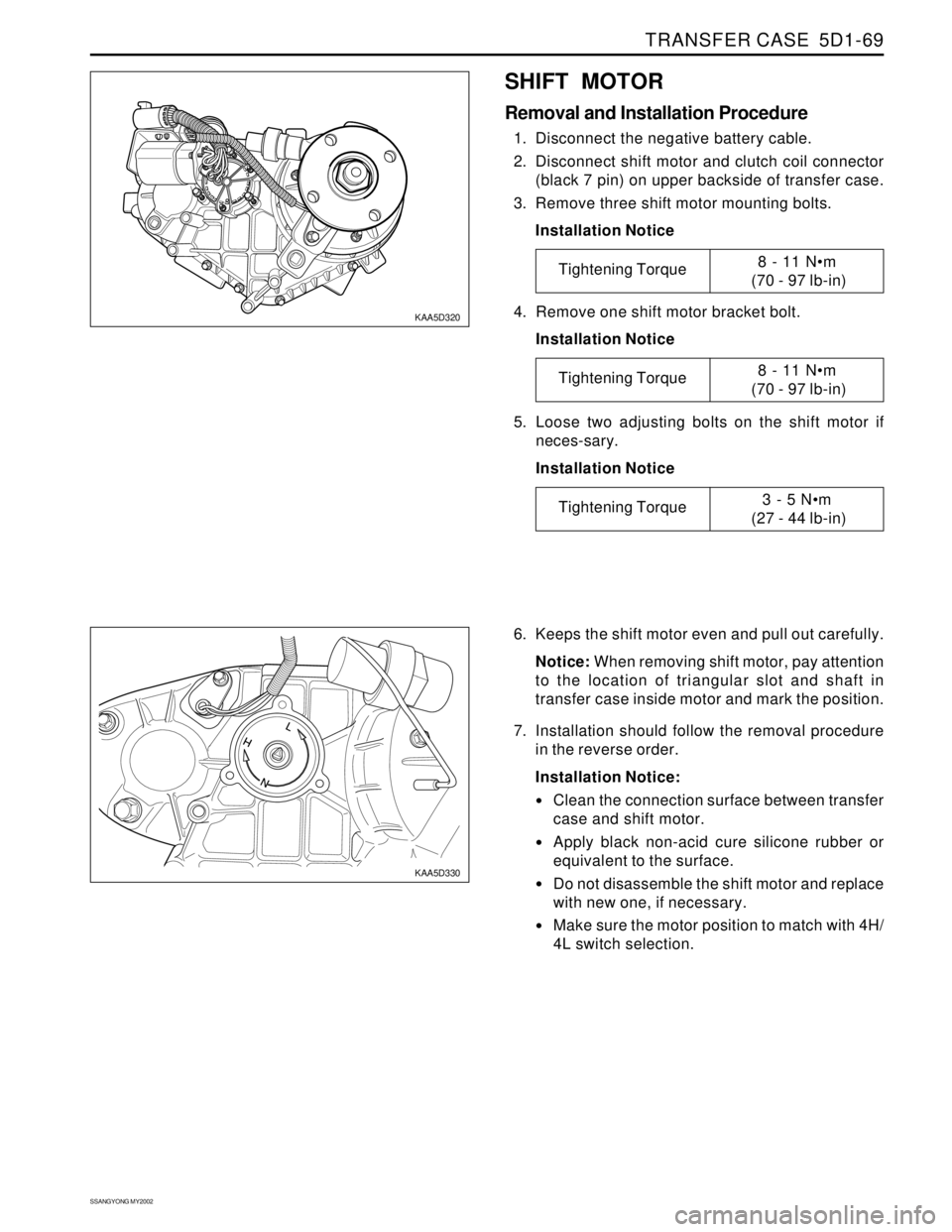
Removal and Installation Procedure
1. Disconnect the negative battery cable.
2. Disconnect shift motor and clutch coil connector
(black 7 pin) on upper backside of transfer case.
3. Remove three shift motor mounting bolts.
Installation Notice
6. Keeps the shift motor even and pull out carefully.
Notice: When removing shift motor, pay attention
to the location of triangular slot and shaft in
transfer case inside motor and mark the position.
7. Installation should follow the removal procedure
in the reverse order.
Installation Notice:
Clean the connection surface between transfer
case and shift motor.
Apply black non-acid cure silicone rubber or
equivalent to the surface.
Do not disassemble the shift motor and replace
with new one, if necessary.
Make sure the motor position to match with 4H/
4L switch selection. 4. Remove one shift motor bracket bolt.
Installation Notice
5. Loose two adjusting bolts on the shift motor if
neces-sary.
Installation Notice
Tightening Torque8 - 11 Nm
(70 - 97 lb-in)
Tightening Torque8 - 11 Nm
(70 - 97 lb-in)
Tightening Torque3 - 5 Nm
(27 - 44 lb-in)
Page 1392 of 2053
SSANGYONG MY2002
5D1-70 TRANSFER CASE
KAA5D340
KAA5D350
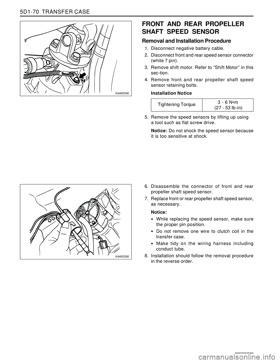
FRONT AND REAR PROPELLER
SHAFT SPEED SENSOR
Removal and Installation Procedure
1. Disconnect negative battery cable.
2. Disconnect front and rear speed sensor connector
(white 7 pin).
3. Remove shift motor. Refer to “Shift Motor” in this
sec-tion.
4. Remove front and rear propeller shaft speed
sensor retaining bolts.
Installation Notice
6. Disassemble the connector of front and rear
propeller shaft speed sensor.
7. Replace front or rear propeller shaft speed sensor,
as necessary.
Notice:
While replacing the speed sensor, make sure
the proper pin position.
Do not remove one wire to clutch coil in the
transfer case.
Make tidy on the wiring harness including
conduct tube.
8. Installation should follow the removal procedure
in the reverse order. 5. Remove the speed sensors by lifting up using
a tool such as flat screw drive.
Notice: Do not shock the speed sensor because
it is too sensitive at shock.
Tightening Torque3 - 6 Nm
(27 - 53 lb-in)