Page 1428 of 2053
SSANGYONG MY2002
5D2-30 TRANSFER CASE (PART TIME - 4408)
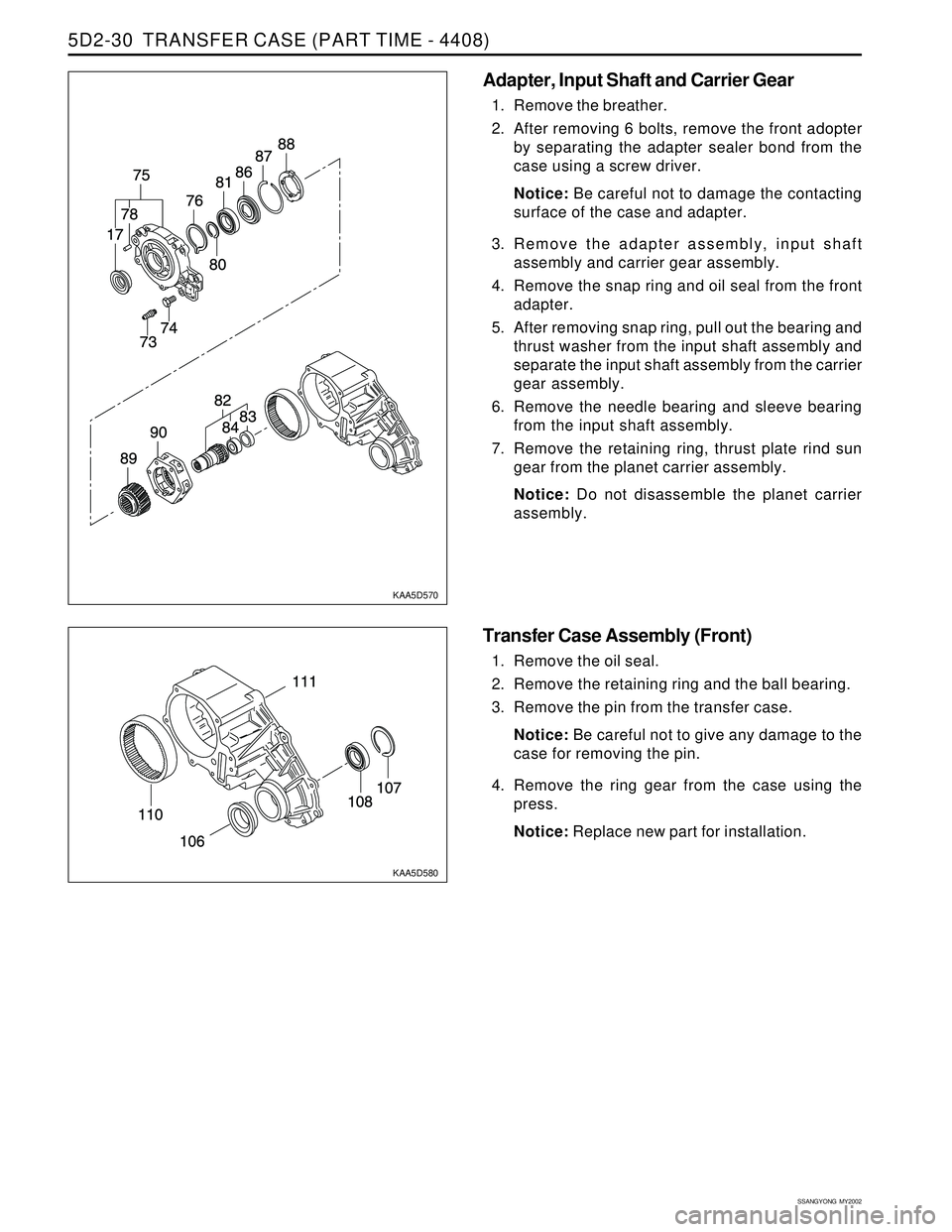
KAA5D570
KAA5D580
Adapter, Input Shaft and Carrier Gear
1. Remove the breather.
2. After removing 6 bolts, remove the front adopter
by separating the adapter sealer bond from the
case using a screw driver.
Notice: Be careful not to damage the contacting
surface of the case and adapter.
3. Remove the adapter assembly, input shaft
assembly and carrier gear assembly.
4. Remove the snap ring and oil seal from the front
adapter.
5. After removing snap ring, pull out the bearing and
thrust washer from the input shaft assembly and
separate the input shaft assembly from the carrier
gear assembly.
6. Remove the needle bearing and sleeve bearing
from the input shaft assembly.
7. Remove the retaining ring, thrust plate rind sun
gear from the planet carrier assembly.
Notice: Do not disassemble the planet carrier
assembly.
Transfer Case Assembly (Front)
1. Remove the oil seal.
2. Remove the retaining ring and the ball bearing.
3. Remove the pin from the transfer case.
Notice: Be careful not to give any damage to the
case for removing the pin.
4. Remove the ring gear from the case using the
press.
Notice: Replace new part for installation.
Page 1429 of 2053
TRANSFER CASE (PART TIME - 4408) 5D2-31
SSANGYONG MY2002
Cleaning Procedure
Notice: Before cleaning, check the magnet for the
presence of metal particles which indicate internal
chipping of the transfer case.
1. Using cleaning solvent, clean the residual oil and
dirt deposits.
Notice: During cleaning, be careful not to damage
the metal surfaces.
2. After cleaning, dry the parts with low pressure(Max.
20 psi) compressed air.
3. Lubricate the ball bearings and needle bearings
with transfer case oil after cleaning.
Notice: Protect the lubricated bearings from dust.
Inspection Procedure
1. Visually check the all removed parts.
Notice: Always replace the hose coupling, O-ring
and oil seal with new parts.
2. Inspection Terms
Burr : Local rise of material forming protruding
sharp edge
Chip : An area from which a small fragment has
been broken off or cut
Crack : Surface break of line nature indicating
partial or complete separation of material.
Excessive wear : Heavy or obvious wear beyond
expectations considering conditions of
operation.
Indentation : Displacement of material caused
by localized heavy contact.
Galling : Breakdown of metal surface due to
excessive friction between parts. Particles of
the softer material are torn loose and welded to
the harder material.
Nick : Local break or notch, usually displacement
of material rather than loss.
Scoring : Tear or break in metal surface from
contact under abnormal pressure.
Page 1434 of 2053
TRANSFER CASE (PART TIME - 4408) 5D2-35
SSANGYONG MY2002
KAA5D750
KAA5D760
KAA5D770
ASSEMBLY PROCEDURE
Use special tools during assembly of oil seals and
bearings.
Lubricate bearings, oil seals and bushings before
assembly.
Transfer Case Assembly
1. If the ring gear was removed, align the outer
diameter of the new replaced ring gear with transfer
case and assemble it.
2. Insert the pin.
3. Insert the ball bearing to the case and install the
retaining ring.
4. Install the new oil seal by pressing into the case.
5. Make sure that all parts are correctly and firmly
installed into the case.
Electric Shift Cam Parts
1. Insert the spacer into torsion spring.
2. Insert the end of the shift shaft into the spacer
smoothly.
Page 1436 of 2053
TRANSFER CASE (PART TIME - 4408) 5D2-37
SSANGYONG MY2002
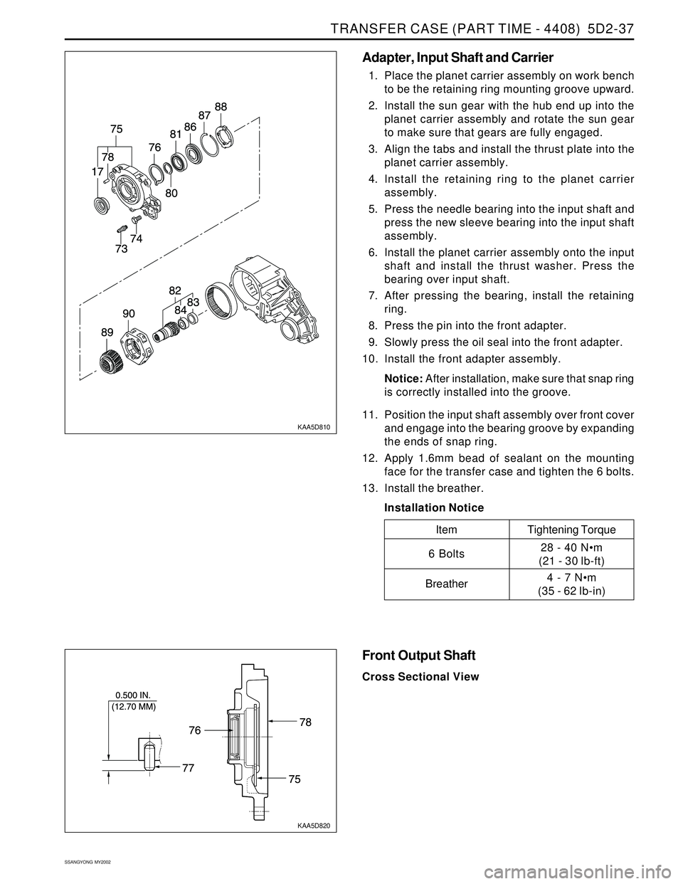
KAA5D810
KAA5D820
Adapter, Input Shaft and Carrier
1. Place the planet carrier assembly on work bench
to be the retaining ring mounting groove upward.
2. Install the sun gear with the hub end up into the
planet carrier assembly and rotate the sun gear
to make sure that gears are fully engaged.
3. Align the tabs and install the thrust plate into the
planet carrier assembly.
4. Install the retaining ring to the planet carrier
assembly.
5. Press the needle bearing into the input shaft and
press the new sleeve bearing into the input shaft
assembly.
6. Install the planet carrier assembly onto the input
shaft and install the thrust washer. Press the
bearing over input shaft.
7. After pressing the bearing, install the retaining
ring.
8. Press the pin into the front adapter.
9. Slowly press the oil seal into the front adapter.
10. Install the front adapter assembly.
Notice: After installation, make sure that snap ring
is correctly installed into the groove.
11. Position the input shaft assembly over front cover
and engage into the bearing groove by expanding
the ends of snap ring.
12. Apply 1.6mm bead of sealant on the mounting
face for the transfer case and tighten the 6 bolts.
13. Install the breather.
Installation Notice
Tightening Torque
28 - 40 Nm
(21 - 30 lb-ft)
4 - 7 Nm
(35 - 62 lb-in)
Item
6 Bolts
Breather
Front Output Shaft
Cross Sectional View
Page 1437 of 2053
SSANGYONG MY2002
5D2-38 TRANSFER CASE (PART TIME - 4408)
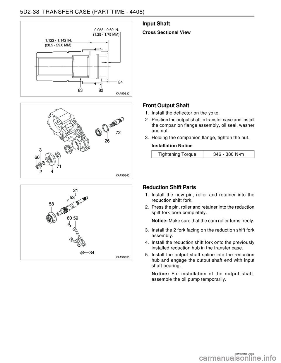
KAA5D830
KAA5D840
KAA5D850
Input Shaft
Cross Sectional View
Tightening Torque346 - 380 Nm
Front Output Shaft
1. Install the deflector on the yoke.
2. Position the output shaft in transfer case and install
the companion flange assembly, oil seal, washer
and nut.
3. Holding the companion flange, tighten the nut.
Installation Notice
Reduction Shift Parts
1. Install the new pin, roller and retainer into the
reduction shift fork.
2. Press the pin, roller and retainer into the reduction
spilt fork bore completely.
Notice: Make sure that the cam roller turns freely.
3. Install the 2 fork facing on the reduction shift fork
assembly.
4. Install the reduction shift fork onto the previously
installed reduction hub in the transfer case.
5. Install the output shaft spline into the reduction
hub and engage the output shaft end with input
shaft bearing.
Notice: For installation of the output shaft,
assemble the oil pump temporarily.
Page 1438 of 2053
TRANSFER CASE (PART TIME - 4408) 5D2-39
SSANGYONG MY2002
KAA5D860
KAA5D870
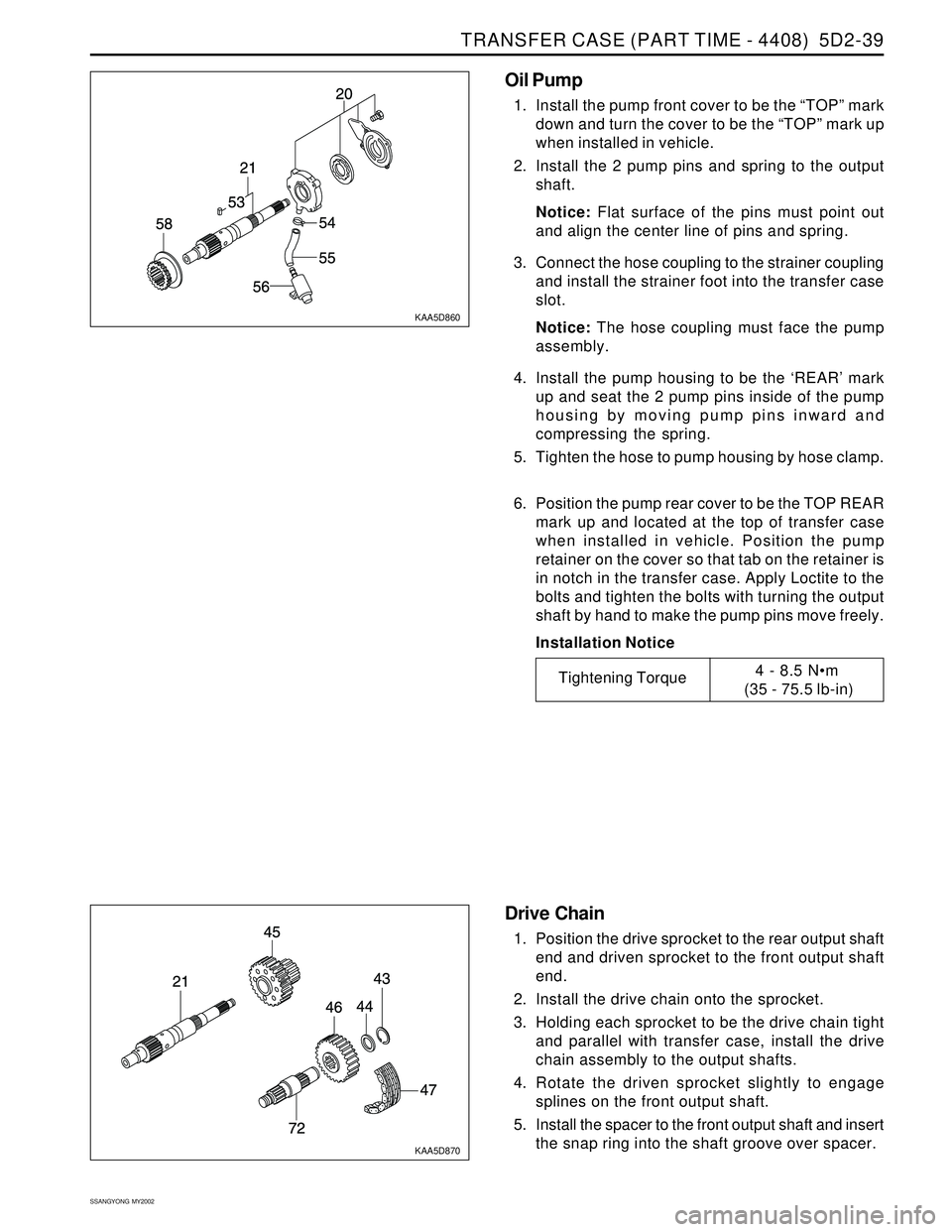
Oil Pump
1. Install the pump front cover to be the “TOP” mark
down and turn the cover to be the “TOP” mark up
when installed in vehicle.
2. Install the 2 pump pins and spring to the output
shaft.
Notice: Flat surface of the pins must point out
and align the center line of pins and spring.
3. Connect the hose coupling to the strainer coupling
and install the strainer foot into the transfer case
slot.
Notice: The hose coupling must face the pump
assembly.
4. Install the pump housing to be the ‘REAR’ mark
up and seat the 2 pump pins inside of the pump
housing by moving pump pins inward and
compressing the spring.
5. Tighten the hose to pump housing by hose clamp.
6. Position the pump rear cover to be the TOP REAR
mark up and located at the top of transfer case
when installed in vehicle. Position the pump
retainer on the cover so that tab on the retainer is
in notch in the transfer case. Apply Loctite to the
bolts and tighten the bolts with turning the output
shaft by hand to make the pump pins move freely.
Installation Notice
Tightening Torque4 - 8.5 Nm
(35 - 75.5 lb-in)
Drive Chain
1. Position the drive sprocket to the rear output shaft
end and driven sprocket to the front output shaft
end.
2. Install the drive chain onto the sprocket.
3. Holding each sprocket to be the drive chain tight
and parallel with transfer case, install the drive
chain assembly to the output shafts.
4. Rotate the driven sprocket slightly to engage
splines on the front output shaft.
5. Install the spacer to the front output shaft and insert
the snap ring into the shaft groove over spacer.
Page 1440 of 2053
TRANSFER CASE (PART TIME - 4408) 5D2-41
SSANGYONG MY2002
KAA5D900
Tightening Torque8 - 11 Nm
(71 - 97 lb-in)
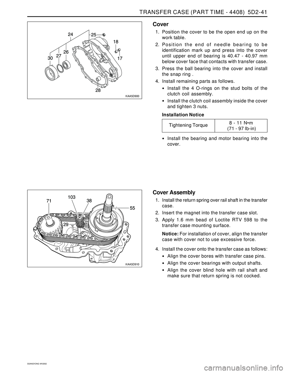
Cover
1. Position the cover to be the open end up on the
work table.
2. Position the end of needle bearing to be
identification mark up and press into the cover
until upper end of bearing is 40.47 - 40.97 mm
below cover face that contacts with transfer case.
3. Press the ball bearing into the cover and install
the snap ring .
4. Install remaining parts as follows.
Install the 4 O-rings on the stud bolts of the
clutch coil assembly.
Install the clutch coil assembly inside the cover
and tighten 3 nuts.
Installation Notice
Install the bearing and motor bearing into the
cover.
KAA5D910
Cover Assembly
1. Install the return spring over rail shaft in the transfer
case.
2. Insert the magnet into the transfer case slot.
3. Apply 1.6 mm bead of Loctite RTV 598 to the
transfer case mounting surface.
Notice: For installation of cover, align the transfer
case with cover not to use excessive force.
4. Install the cover onto the transfer case as follows:
Align the cover bores with transfer case pins.
Align the cover bearings with output shafts.
Align the cover blind hole with rail shaft and
make sure that return spring is not cocked.
Page 1441 of 2053
SSANGYONG MY2002
5D2-42 TRANSFER CASE (PART TIME - 4408)
5. Tighten 9 bolts positioning identification tag and
wiring clip.
Installation Notice
6. Install the speed gear over output shaft spline in
the cover assembly.
7. Press the new oil seal into the cover assembly.
Tightening Torque28 - 40 Nm
(21 - 30 lb-ft)
KAA5D920
KAA5D930
KAA5D940
External Electric Shift
1. Align the motor with shift shaft and position the
motor assembly onto the cover.
2. Install the motor to the shift shaft and contact
cover and rotate the motor clockwise direction to
check correct engagement.
3. Insert the O-ring on the speed sensor assembly
to the cover.
4. Install the bracket to the motor assembly and
tighten 3 bolts.
Installation Notice
Tightening Torque8 - 11 Nm
(71 - 97 lb-in)