Page 1321 of 2053
MANUAL TRANSMISSION 5B-13
SSANGYONG MY2002
115 Bolt
116 Spacer Seal and O-ring
117 Pivot Pin
118 Back-up Switch
119 Transmission Case
120 Filler/Drain Plug
121 Plug
122 Bolt123 Input Bearing Retainer
124 Oil Seal
125 Shim
126 Bearing Cap
127 Bearing Corn
128 Input Drive Shaft
129 Roller Bearing
Page 1327 of 2053
MANUAL TRANSMISSION 5B-19
SSANGYONG MY2002
TRANSMISSION
Removal Procedure
1. Disconnect the negative terminal from the battery.
2. Lift up the vehicle and fix it safely.
3. Remove the drain plug from the transmission
housing and drain the oil. Reinstall the drain plug.
4. Disconnect the back-up switch connector.
5. Remove the breather hose.
YAD5B280
YAD5B290
YAD5B300
YAD5B310
6. Remove the speedometer connector and other
wiring harnesses and connectors.
Page 1331 of 2053
MANUAL TRANSMISSION 5B-23
SSANGYONG MY2002
4. Install the front and rear propeller shafts to the
transmission.
Installation Notice
5. Connect the cable, the harness and the bleeder.
6. Install the back lamp switch.
7. Install the speedometer cable.
YAD5B430
YAD5B440
YAD5B450
YAD5B310
81 - 89 Nm
(60 - 66 lb-ft)
70 - 90 Nm
(52 - 66 lb-ft)
Tightening
TorqueFront
Rear
8. Charge the approved oil in the transmission
housing and tighten the drain plug and the filler
plug.
Installation Notice
Oil25 Nm (18 lb-ft)
25 Nm (18 lb-ft)
Tightening
TorqueFiller Plug
Drain Plug
Spec.
Capacity
3.4L
2.0L
4WD
2WDATF Dexron II
Page 1332 of 2053
SSANGYONG MY2002
5B-24 MANUAL TRANSMISSION
UNIT REPAIR
MAJOR UNIT
Disassembly Procedure
1. Remove the shift lever from the extension housing.
YAD5B470
YAD5B480
YAD5B500
YAD5B490
2. Install the removed transmission into a fixture.
3. Remove the drain plug and drain the oil. Using a
10 mm wrench, remove the clamp bolt and position
the offset lever in the 3-4 position of neutral.
Notice: Removal of the offset lever in a position
other than 3-4 of neutral will be difficult.
4. Using a pin punch and a hammer, remove the roll
pin to remove the shift lever from the offset lever.
5. Using a 15 mm wrench, remove the 8 bolts from
the extension housing.
6. Separate the extension housing from the case and
shift cover.
Separate the offset lever from the shift.
Notice: Do not remove the offset lever while the
extension housing is still assembled to the case.
Page 1333 of 2053
MANUAL TRANSMISSION 5B-25
SSANGYONG MY2002
7. Remove the offset lever from the extension
housing with the detent ball and spring.
8. Remove the roll pin from either the offset lever or
extension housing.
YAD5B510
YAD5B520
YAD5B540
YAD5B530
9. Remove the counter shaft thrust race and bearing.
10. Carefully remove the oiling funnel from the end of
the counter shaft.
11. Using a 10 mm wrench, remove the 10 bolts from
the shift cover.
Notice: For assembly, note the location of the two
bolts.
12. Lift up the shift cover after sliding it toward the
drain plug about 3 cm. At this time remove sealer
bond.
Page 1339 of 2053
MANUAL TRANSMISSION 5B-31
SSANGYONG MY2002
7. Install the counter shaft rear bearing outer race,
shim and retainer.
Installation Notice
Notice: Using a punch and hammer, bend the lock
tabs on the retainer.
YAD5B750
YAD5B760
YAD5B770
8. Install the following parts :
Install the main shaft into case.
Install the main shaft rear bearing outer race
into the rear of the case.
Install the 4th speed blocking ring onto the front
of the main shaft.
Install the input shaft onto the front of the main
shaft.
Install the input bearing retainer without shim
onto the front of the case.
Using a torque wrench, tighten the 4 bolts.
Installation Notice
9. Install the 5th speed drive gear and blocking ring
on the counter shaft.
10. Install the 5th synchronizer and rail/fork.
11. Install the 5th synchronizer snap ring and oiling
funnel.
Tightening Torque 20 Nm (15 lb-ft)
Tightening Torque 20 Nm (15 lb-ft)
Page 1357 of 2053

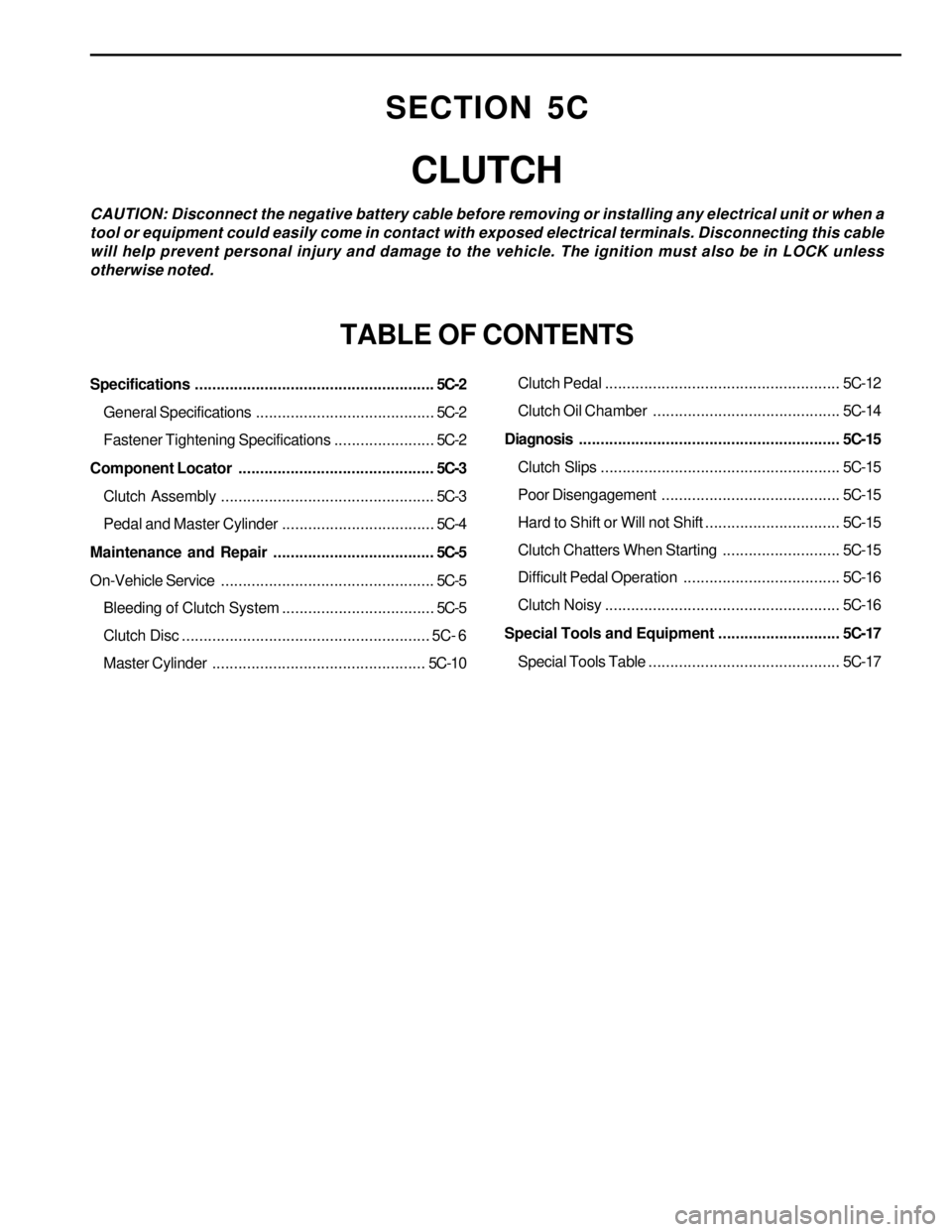
Specifications.......................................................5C-2
General Specifications.........................................5C-2
Fastener Tightening Specifications.......................5C-2
Component Locator.............................................5C-3
Clutch Assembly.................................................5C-3
Pedal and Master Cylinder...................................5C-4
Maintenance and Repair.....................................5C-5
On-Vehicle Service.................................................5C-5
Bleeding of Clutch System...................................5C-5
Clutch Disc......................................................... 5C- 6
Master Cylinder.................................................5C-10Clutch Pedal...................................................... 5C-12
Clutch Oil Chamber........................................... 5C-14
Diagnosis............................................................ 5C-15
Clutch Slips....................................................... 5C-15
Poor Disengagement ......................................... 5C-15
Hard to Shift or Will not Shift............................... 5C-15
Clutch Chatters When Starting........................... 5C-15
Difficult Pedal Operation.................................... 5C-16
Clutch Noisy...................................................... 5C-16
Special Tools and Equipment............................ 5C-17
Special Tools Table............................................ 5C-17
SECTION 5C
CLUTCH
CAUTION: Disconnect the negative battery cable before removing or installing any electrical unit or when a
tool or equipment could easily come in contact with exposed electrical terminals. Disconnecting this cable
will help prevent personal injury and damage to the vehicle. The ignition must also be in LOCK unless
otherwise noted.
TABLE OF CONTENTS
Page 1363 of 2053
SSAMGYONG MY2002
5C-8 CLUTCH
5. Unscrew the bolts and remove the clutch cover,
pressure plate and clutch disc.
Notice: Be careful not to drop the pressure plate
and clutch disc.
Installation Notice
6. Installation should follow the removal procedure
in the reverse order.
Notice:
Before installation, clean oil and grease on the
flywheel surface.
Do not clean the clutch disc and release bearing
in solvent.
2. Clutch Disc
Check the facing for rivet looseness, excessive
runout, sticks, oil and grease.
Measure the rivet head depth.
If out limit, replace the disc.
Inspection Procedure
1. Clutch Cover
Check the diaphragm spring tip for wear and
height unevenness.
Check the pressure plate surface for wear, crack
and discoloration.
Check the strap plate rivet for looseness and
replace the clutch cover if loosened.
KAA5C090
KAA5C100
KAA5C110
Tightening Torque21 - 27 Nm
(15 - 20 lb-ft)
Wear Limit 0.3 mm
Unevenness Limit 0.8 mm