Page 1379 of 2543
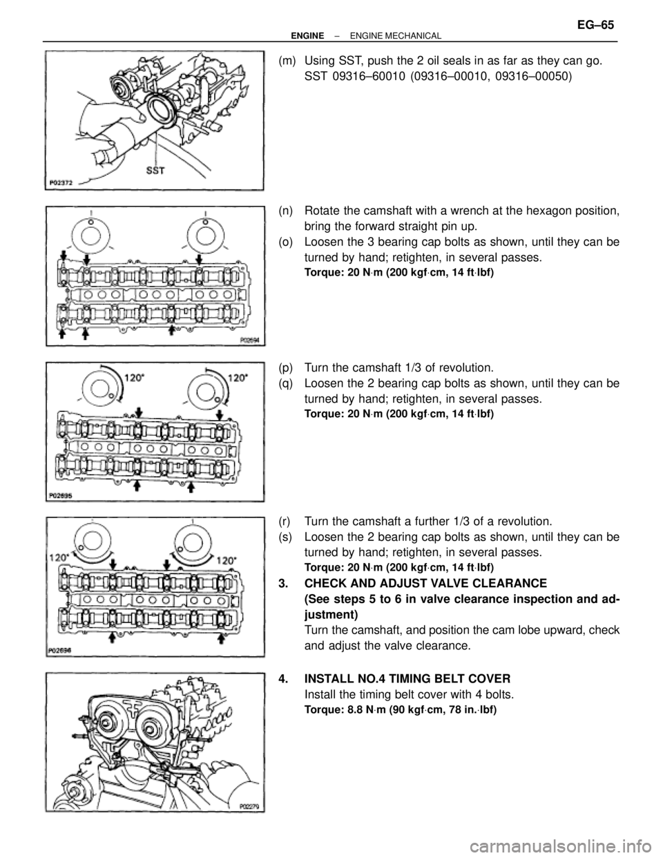
(m) Using SST, push the 2 oil seals in as far as they can go.
SST 09316±60010 (09316±00010, 09316±00050)
(n) Rotate the camshaft with a wrench at the hexagon position,
bring the forward straight pin up.
(o) Loosen the 3 bearing cap bolts as shown, until they can be
turned by hand; retighten, in several passes.
Torque: 20 NVm (200 kgfVcm, 14 ftVlbf)
(p) Turn the camshaft 1/3 of revolution.
(q) Loosen the 2 bearing cap bolts as shown, until they can be
turned by hand; retighten, in several passes.
Torque: 20 NVm (200 kgfVcm, 14 ftVlbf)
(r) Turn the camshaft a further 1/3 of a revolution.
(s) Loosen the 2 bearing cap bolts as shown, until they can be
turned by hand; retighten, in several passes.
Torque: 20 NVm (200 kgfVcm, 14 ftVlbf)
3. CHECK AND ADJUST VALVE CLEARANCE
(See steps 5 to 6 in valve clearance inspection and ad-
justment)
Turn the camshaft, and position the cam lobe upward, check
and adjust the valve clearance.
4. INSTALL NO.4 TIMING BELT COVER
Install the timing belt cover with 4 bolts.
Torque: 8.8 NVm (90 kgfVcm, 78 in.Vlbf)
± ENGINEENGINE MECHANICALEG±65
Page 1381 of 2543
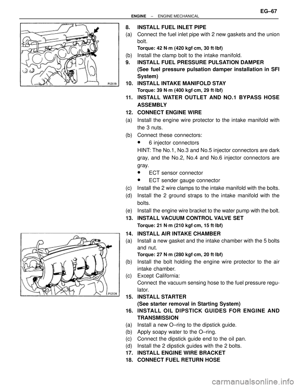
8. INSTALL FUEL INLET PIPE
(a) Connect the fuel inlet pipe with 2 new gaskets and the union
bolt.
Torque: 42 NVm (420 kgfVcm, 30 ftVlbf)
(b) Install the clamp bolt to the intake manifold.
9. INSTALL FUEL PRESSURE PULSATION DAMPER
(See fuel pressure pulsation damper installation in SFI
System)
10. INSTALL INTAKE MANIFOLD STAY
Torque: 39 NVm (400 kgfVcm, 29 ftVlbf)
11. INSTALL WATER OUTLET AND NO.1 BYPASS HOSE
ASSEMBLY
12. CONNECT ENGINE WIRE
(a) Install the engine wire protector to the intake manifold with
the 3 nuts.
(b) Connect these connectors:
w6 injector connectors
HINT: The No.1, No.3 and No.5 injector connectors are dark
gray, and the No.2, No.4 and No.6 injector connectors are
gray.
wECT sensor connector
wECT sender gauge connector
(c) Install the 2 wire clamps to the intake manifold with the bolts.
(d) Install the 2 ground straps to the intake manifold with the
bolts.
(e) Install the engine wire bracket to the water pump with the bolt.
13. INSTALL VACUUM CONTROL VALVE SET
Torque: 21 NVm (210 kgfVcm, 15 ftVlbf)
14. INSTALL AIR INTAKE CHAMBER
(a) Install a new gasket and the intake chamber with the 5 bolts
and nut.
Torque: 27 NVm (280 kgfVcm, 20 ftVlbf)
(b) Install the bolt holding the engine wire protector to the air
intake chamber.
(c) Except California:
Connect the vacuum sensing hose to the fuel pressure regu-
lator.
15. INSTALL STARTER
(See starter removal in Starting System)
16. INS TALL OIL DIP S TICK GUIDE S FO R ENG INE AND
TRANSMISSION
(a) Install a new O±ring to the dipstick guide.
(b) Apply soapy water to the O±ring.
(c) Connect the dipstick guide end to the oil pan.
(d) Install the 2 dipstick guides with the 2 bolts.
17. INSTALL ENGINE WIRE BRACKET
18. CONNECT FUEL RETURN HOSE
± ENGINEENGINE MECHANICALEG±67
Page 1384 of 2543
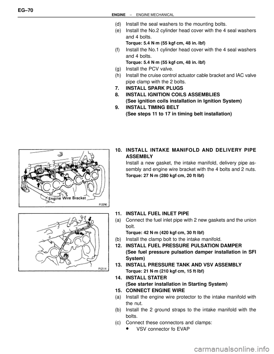
(d) Install the seal washers to the mounting bolts.
(e) Install the No.2 cylinder head cover with the 4 seal washers
and 4 bolts.
Torque: 5.4 NVm (55 kgfVcm, 48 in.Vlbf)
(f) Install the No.1 cylinder head cover with the 4 seal washers
and 4 bolts.
Torque: 5.4 NVm (55 kgfVcm, 48 in.Vlbf)
(g) Install the PCV valve.
(h) Install the cruise control actuator cable bracket and IAC valve
pipe clamp with the 2 bolts.
7. INSTALL SPARK PLUGS
8. INSTALL IGNITION COILS ASSEMBLIES
(See ignition coils installation in Ignition System)
9. INSTALL TIMING BELT
(See steps 11 to 17 in timing belt installation)
10. INS TALL INTAKE MANIFO LD AND DE LIV E RY PIP E
ASSEMBLY
Install a new gasket, the intake manifold, delivery pipe as-
sembly and engine wire bracket with the 4 bolts and 2 nuts.
Torque: 27 NVm (280 kgfVcm, 20 ftVlbf)
11. INSTALL FUEL INLET PIPE
(a) Connect the fuel inlet pipe with 2 new gaskets and the union
bolt.
Torque: 42 NVm (420 kgfVcm, 30 ftVlbf)
(b) Install the clamp bolt to the intake manifold.
12. INSTALL FUEL PRESSURE PULSATION DAMPER
(See fuel pressure pulsation damper installation in SFI
System)
13. INSTALL PRESSURE TANK AND VSV ASSEMBLY
Torque: 21 NVm (210 kgfVcm, 15 ftVlbf)
14. INSTALL STATER
(See starter installation in Starting System)
15. CONNECT ENGINE WIRE
(a) Install the engine wire protector to the intake manifold with
the nut.
(b) Install the 2 ground straps to the intake manifold with the
bolts.
(c) Connect these connectors and clamps:
wVSV connector fo EVAP EG±70
± ENGINEENGINE MECHANICAL
Page 1392 of 2543
ENGINE REMOVAL (2JZ±GE)
1. REMOVE HOOD
2. REMOVE RADIATOR ASSEMBLY
(See radiator removal in Cooling System)
3. DRAIN ENGINE OIL
4. DRAIN FUEL FROM FUEL TANK
5. DISCONNECT CONTROL CABLES FROM THROTTLE
BODY
Disconnect these cables:
wAccelerator cable
wCruise control actuator cable
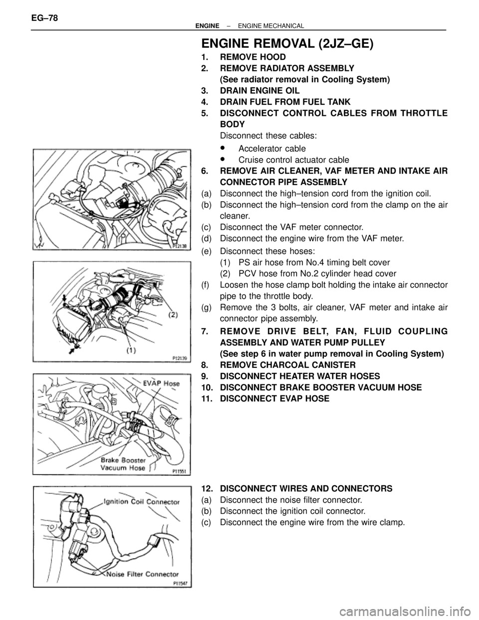
6. REMOVE AIR CLEANER, VAF METER AND INTAKE AIR
CONNECTOR PIPE ASSEMBLY
(a) Disconnect the high±tension cord from the ignition coil.
(b) Disconnect the high±tension cord from the clamp on the air
cleaner.
(c) Disconnect the VAF meter connector.
(d) Disconnect the engine wire from the VAF meter.
(e) Disconnect these hoses:
(1) PS air hose from No.4 timing belt cover
(2) PCV hose from No.2 cylinder head cover
(f) Loosen the hose clamp bolt holding the intake air connector
pipe to the throttle body.
(g) Remove the 3 bolts, air cleaner, VAF meter and intake air
connector pipe assembly.
7. REMOVE DRIVE BELT, FAN, FLUID COUPLING
ASSEMBLY AND WATER PUMP PULLEY
(See step 6 in water pump removal in Cooling System)
8. REMOVE CHARCOAL CANISTER
9. DISCONNECT HEATER WATER HOSES
10. DISCONNECT BRAKE BOOSTER VACUUM HOSE
11. DISCONNECT EVAP HOSE
12. DISCONNECT WIRES AND CONNECTORS
(a) Disconnect the noise filter connector.
(b) Disconnect the ignition coil connector.
(c) Disconnect the engine wire from the wire clamp. EG±78
± ENGINEENGINE MECHANICAL
Page 1394 of 2543
13. DISCONNECT FUEL HOSES
(a) Remove the union bolt and 2 gaskets, disconnect the fuel
inlet hose.
HINT:
wPut a suitable container or shop rag under the fuel pipe
support.
wSlowly loosen the union bolt.
(b) Suspend the hose union end upward.
(c) Disconnect the fuel return hose from the oil dipstick guide.
(d) Disconnect the fuel return hose from the fuel return hose.
Plug the hose end.
14. REMOVE ENGINE WIRE BRACKET
Remove the bolt and bracket, and disconnect the engine wire
from the intake manifold stay.
15. DISCONNECT PS PUMP WITHOUT DISCONNECTING
HOSES
(a) Remove the 3 bolts, plate washer and pump front bracket.
(b) Disconnect these hoses:
(1) Air hose from No.4 timing belt cover
(2) Air hose from air intake chamber
(c) Disconnect the pump housing from the pump bracket.
HINT: Put aside the pump housing, and suspend it.
(d) Remove the 2 bolts and pump rear stay.
(e) Remove the 2 bolts and pump bracket. EG±80
± ENGINEENGINE MECHANICAL
Page 1398 of 2543
25. A/T:
DISCONNECT TRANSMISSION CONTROL ROD
Remove the nut, and disconnect the control rod from the shift
lever.
26. M/T:
REMOVE TRANSMISSION SHIFT LEVER
(a) Remove the bolt and nut.
(b) Remove the transmission shift lever, inside of vehicle.
27. PLACE JACK UNDER TRANSMISSION
NOTICE (A/T): Be sure to put a wooden block between the jack
and the transmission oil pan to prevent damage.
28. REMOVE REAR SUPPORT MEMBER
(a) Remove the 4 nuts holding the member to the engine rear
mounting insulator.
(b) Remove the 4 bolts and rear support member.
29. REMOVE ENGINE AND TRANSMISSION ASSEMBLY
FROM VEHICLE
(a) Attach the engine hoist chain to the 2 engine hangers.
(b) Remove the 2 nuts holding the engine front mounting
insulators to the front suspension crossmember. EG±84
± ENGINEENGINE MECHANICAL
Page 1399 of 2543
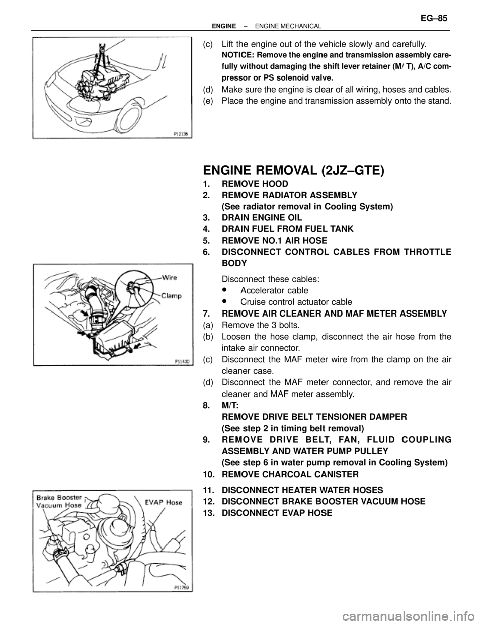
(c) Lift the engine out of the vehicle slowly and carefully.
NOTICE: Remove the engine and transmission assembly care-
fully without damaging the shift lever retainer (M/ T), A/C com-
pressor or PS solenoid valve.
(d) Make sure the engine is clear of all wiring, hoses and cables.
(e) Place the engine and transmission assembly onto the stand.
ENGINE REMOVAL (2JZ±GTE)
1. REMOVE HOOD
2. REMOVE RADIATOR ASSEMBLY
(See radiator removal in Cooling System)
3. DRAIN ENGINE OIL
4. DRAIN FUEL FROM FUEL TANK
5. REMOVE NO.1 AIR HOSE
6. DISCONNECT CONTROL CABLES FROM THROTTLE
BODY
Disconnect these cables:
wAccelerator cable
wCruise control actuator cable
7. REMOVE AIR CLEANER AND MAF METER ASSEMBLY
(a) Remove the 3 bolts.
(b) Loosen the hose clamp, disconnect the air hose from the
intake air connector.
(c) Disconnect the MAF meter wire from the clamp on the air
cleaner case.
(d) Disconnect the MAF meter connector, and remove the air
cleaner and MAF meter assembly.
8. M/T:
REMOVE DRIVE BELT TENSIONER DAMPER
(See step 2 in timing belt removal)
9. REMOVE DRIVE BELT, FAN, FLUID COUPLING
ASSEMBLY AND WATER PUMP PULLEY
(See step 6 in water pump removal in Cooling System)
10. REMOVE CHARCOAL CANISTER
11. DISCONNECT HEATER WATER HOSES
12. DISCONNECT BRAKE BOOSTER VACUUM HOSE
13. DISCONNECT EVAP HOSE
± ENGINEENGINE MECHANICALEG±85
Page 1406 of 2543
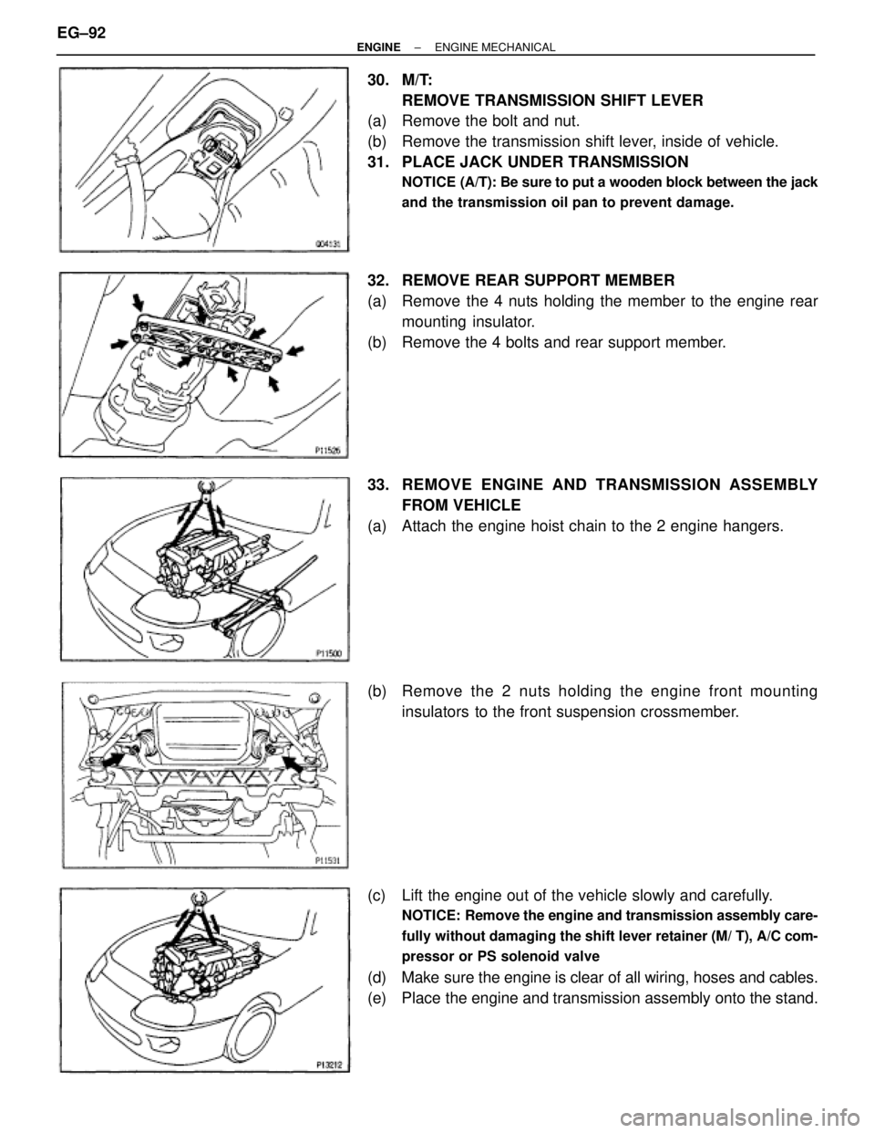
30. M/T:
REMOVE TRANSMISSION SHIFT LEVER
(a) Remove the bolt and nut.
(b) Remove the transmission shift lever, inside of vehicle.
31. PLACE JACK UNDER TRANSMISSION
NOTICE (A/T): Be sure to put a wooden block between the jack
and the transmission oil pan to prevent damage.
32. REMOVE REAR SUPPORT MEMBER
(a) Remove the 4 nuts holding the member to the engine rear
mounting insulator.
(b) Remove the 4 bolts and rear support member.
33. REMOVE ENGINE AND TRANSMISSION ASSEMBLY
FROM VEHICLE
(a) Attach the engine hoist chain to the 2 engine hangers.
(b) Remove the 2 nuts holding the engine front mounting
insulators to the front suspension crossmember.
(c) Lift the engine out of the vehicle slowly and carefully.
NOTICE: Remove the engine and transmission assembly care-
fully without damaging the shift lever retainer (M/ T), A/C com-
pressor or PS solenoid valve
(d) Make sure the engine is clear of all wiring, hoses and cables.
(e) Place the engine and transmission assembly onto the stand. EG±92
± ENGINEENGINE MECHANICAL