Page 1320 of 2543
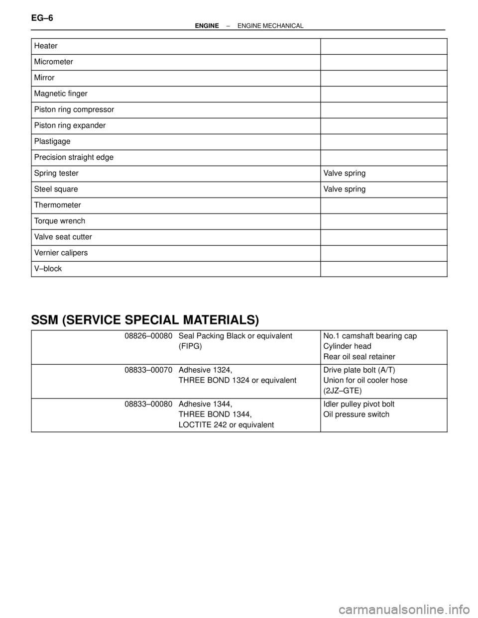
������������������������� �������������������������Heater������������ ������������
������������������������� �������������������������Micrometer������������ ������������
������������������������� �
������������������������ �������������������������Mirror
������������ �
����������� ������������
������������������������� �������������������������Magnetic finger������������ ������������
������������������������� �������������������������Piston ring compressor������������ ������������
������������������������� �
������������������������ �������������������������Piston ring expander
������������ �
����������� ������������
������������������������� �������������������������Plastigage������������ ������������
������������������������� �������������������������Precision straight edge������������ ������������
������������������������� �
������������������������ �������������������������Spring tester
������������ �
����������� ������������Valve spring
������������������������� �������������������������Steel square������������ ������������Valve spring
������������������������� �������������������������Thermometer������������ ������������
������������������������� �
������������������������ �������������������������Torque wrench������������ �
����������� ������������
������������������������� �������������������������Valve seat cutter������������ ������������
������������������������� �������������������������Vernier calipers������������ ������������
������������������������� �
������������������������ �������������������������V±block������������ �
����������� ������������
SSM (SERVICE SPECIAL MATERIALS)
������������� �
������������ �
������������ �������������
08826±00080������������� �
������������ �
������������ �������������
Seal Packing Black or equivalent
(FIPG)������������ �
����������� �
����������� ������������
No.1 camshaft bearing cap
Cylinder head
Rear oil seal retainer
������������� �
������������ �
������������ �������������
08833±00070������������� �
������������ �
������������ �������������
Adhesive 1324,
THREE BOND 1324 or equivalent������������ �
����������� �
����������� ������������
Drive plate bolt (A/T)
Union for oil cooler hose
(2JZ±GTE)
������������� �
������������ �
������������ �������������
08833±00080������������� �
������������ �
������������ �������������
Adhesive 1344,
THREE BOND 1344,
LOCTITE 242 or equivalent������������ �
����������� �
����������� ������������
Idler pulley pivot bolt
Oil pressure switch
EG±6± ENGINEENGINE MECHANICAL
Page 1323 of 2543
COMPRESSION CHECK
HINT: If there is lack of power, excessive oil consumption or
poor fuel economy, measure the compression pressure.
1. WARM UP AND STOP ENGINE
Allow the engine to warm up to normal operating tempera-
ture.
2. 2JZ±GE:
DISCONNECT DISTRIBUTOR CONNECTOR
3. 2JZ±GTE:
DISCONNECT CAMSHAFT POSITION SENSOR CON-
NECTORS
4. 2JZ±GE:
DISCONNECT HIGH±TENSION CORDS FROM SPARK
PLUGS
(See high±tension cords and cord clamps removal in
Ignition System)
5. 2JZ±GTE:
REMOVE IGNITION COILS ASSEMBLIES
(See ignition coils removal in Ignition System)
6. REMOVE SPARK PLUGS
7. CHECK CYLINDER COMPRESSION
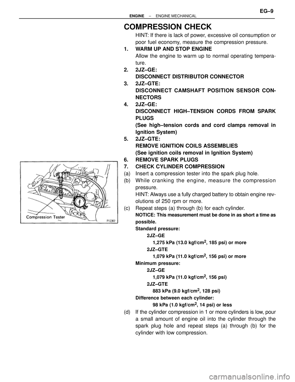
(a) Insert a compression tester into the spark plug hole.
(b) Wh ile cra n kin g th e en g in e , me a su re th e co mp re ssio n
pressure.
HINT: Always use a fully charged battery to obtain engine rev-
olutions of 250 rpm or more.
(c) Repeat steps (a) through (b) for each cylinder.
NOTICE: This measurement must be done in as short a time as
possible.
Standard pressure:
2JZ±GE
1,275 kPa (13.0 kgf/cm
2, 185 psi) or more
2JZ±GTE
1,079 kPa (11.0 kgf/cm
2, 156 psi) or more
Minimum pressure:
2JZ±GE
1,079 kPa (11.0 kgf/cm
2, 156 psi)
2JZ±GTE
883 kPa (9.0 kgf/cm
2, 128 psi)
Difference between each cylinder:
98 kPa (1.0 kgf/cm
2, 14 psi) or less
(d) If the cylinder compression in 1 or more cylinders is low, pour
a small amount of engine oil into the cylinder through the
spark plug hole and repeat steps (a) through (b) for the
cylinder with low compression.
± ENGINEENGINE MECHANICALEG±9
Page 1324 of 2543
wIf adding oil helps the compression, it is likely that the
piston rings and/or cylinder bore are probably worn or
damaged.
wIf pressure stays low, a valve may be sticking or seating
improper, or there may be leakage past the gasket.
8. REINSTALL SPARK PLUGS
9. 2JZ±GE:
RECONNECT HIGH±TENSION CORDS TO SPARK
PLUGS
(See high±tension cords and cord clamps installation in
Ignition System)
10. 2JZ±GTE:
REINSTALL IGNITION COILS ASSEMBLIES
(See ignition coils installation in Ignition System)
11. 2JZ±GE:
RECONNECT DISTRIBUTOR CONNECTOR
12. 2JZ±GTE:
RECONNECT CAMSHAFT POSITION SENSOR CONNEC-
TORS EG±10
± ENGINEENGINE MECHANICAL
Page 1330 of 2543
7. REINSTALL NO.2, NO.1 AND NO.3 CYLINDER HEAD
COVERS
(a) Remove any old packing (FIPG) material.
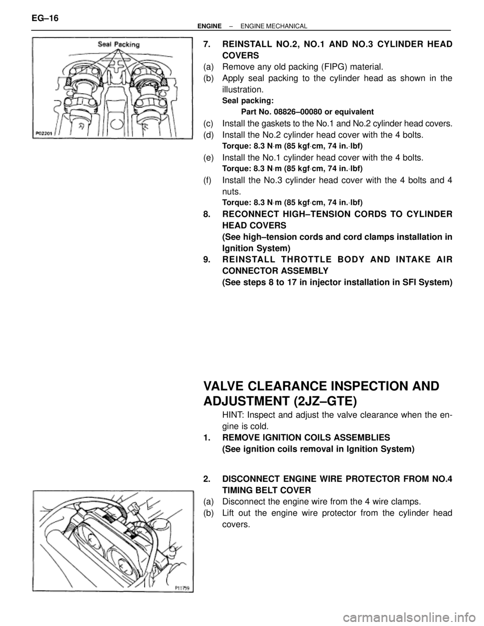
(b) Apply seal packing to the cylinder head as shown in the
illustration.
Seal packing:
Part No. 08826±00080 or equivalent
(c) Install the gaskets to the No.1 and No.2 cylinder head covers.
(d) Install the No.2 cylinder head cover with the 4 bolts.
Torque: 8.3 NVm (85 kgfVcm, 74 in.Vlbf)
(e) Install the No.1 cylinder head cover with the 4 bolts.
Torque: 8.3 NVm (85 kgfVcm, 74 in.Vlbf)
(f) Install the No.3 cylinder head cover with the 4 bolts and 4
nuts.
Torque: 8.3 NVm (85 kgfVcm, 74 in.Vlbf)
8. RECONNECT HIGH±TENSION CORDS TO CYLINDER
HEAD COVERS
(See high±tension cords and cord clamps installation in
Ignition System)
9. REINSTALL THROTTLE BODY AND INTAKE AIR
CONNECTOR ASSEMBLY
(See steps 8 to 17 in injector installation in SFI System)
VALVE CLEARANCE INSPECTION AND
ADJUSTMENT (2JZ±GTE)
HINT: Inspect and adjust the valve clearance when the en-
gine is cold.
1. REMOVE IGNITION COILS ASSEMBLIES
(See ignition coils removal in Ignition System)
2. DISCONNECT ENGINE WIRE PROTECTOR FROM NO.4
TIMING BELT COVER
(a) Disconnect the engine wire from the 4 wire clamps.
(b) Lift out the engine wire protector from the cylinder head
covers. EG±16
± ENGINEENGINE MECHANICAL
Page 1332 of 2543
9. REINSTALL NO.1 AND NO.2 CYLINDER HEAD COVERS
(a) Remove any old packing (FIPG) material.
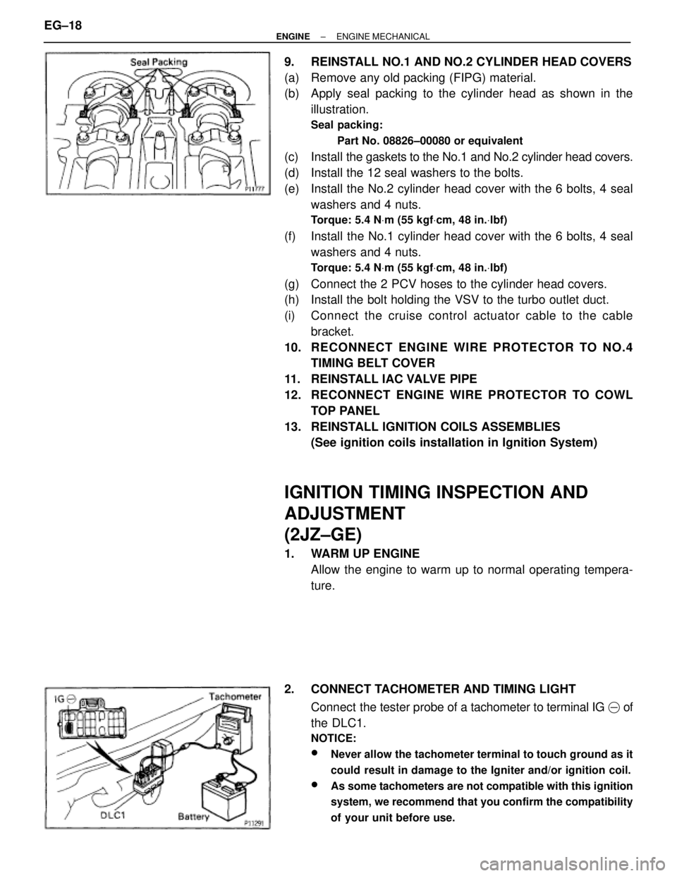
(b) Apply seal packing to the cylinder head as shown in the
illustration.
Seal packing:
Part No. 08826±00080 or equivalent
(c) Install the gaskets to the No.1 and No.2 cylinder head covers.
(d) Install the 12 seal washers to the bolts.
(e) Install the No.2 cylinder head cover with the 6 bolts, 4 seal
washers and 4 nuts.
Torque: 5.4 NVm (55 kgfVcm, 48 in.Vlbf)
(f) Install the No.1 cylinder head cover with the 6 bolts, 4 seal
washers and 4 nuts.
Torque: 5.4 NVm (55 kgfVcm, 48 in.Vlbf)
(g) Connect the 2 PCV hoses to the cylinder head covers.
(h) Install the bolt holding the VSV to the turbo outlet duct.
(i) Connect the cruise control actuator cable to the cable
bracket.
10. RECONNECT ENGINE WIRE PROTECTOR TO NO.4
TIMING BELT COVER
11. REINSTALL IAC VALVE PIPE
12. RECONNECT ENGINE WIRE PROTECTOR TO COWL
TOP PANEL
13. REINSTALL IGNITION COILS ASSEMBLIES
(See ignition coils installation in Ignition System)
IGNITION TIMING INSPECTION AND
ADJUSTMENT
(2JZ±GE)
1. WARM UP ENGINE
Allow the engine to warm up to normal operating tempera-
ture.
2. CONNECT TACHOMETER AND TIMING LIGHT
Connect the tester probe of a tachometer to terminal IG � of
the DLC1.
NOTICE:
wNever allow the tachometer terminal to touch ground as it
could result in damage to the Igniter and/or ignition coil.
wAs some tachometers are not compatible with this ignition
system, we recommend that you confirm the compatibility
of your unit before use.
EG±18± ENGINEENGINE MECHANICAL
Page 1338 of 2543
TIMING BELT REMOVAL
1. REMOVE RADIATOR ASSEMBLY
(See radiator removal in Cooling System)
2. 2JZ±GTE M/T:
REMOVE DRIVE BELT TENSIONER DAMPER
Remove the 2 nuts and tensioner damper.
3. REMOVE DRIVE BELT, FAN, FLUID COUPLING
ASSEMBLY AND WATER PUMP PULLEY
(See step 6 in water pump removal in Cooling System)
4. REMOVE NO.3 TIMING BELT COVER
(a) Remove the oil filler cap.
(b) 2JZ±GE:
Using a 5 mm hexagon wrench, remove the 6 bolts and belt
cover.
(c) 2JZ±GTE:
Using a 5 mm hexagon wrench, remove the 10 bolts and belt
cover.
5. REMOVE NO.2 TIMING BELT COVER
Using a 5 mm hexagon wrench, remove the 3 bolts, belt cover
and gasket.
If you are unable to loosen the bolt on the right because the
PS pump pulley interferes with the hexagon wrench, first re-
move the pulley.
6. REMOVE DRIVE BELT TENSIONER
Remove the 3 bolts and tensioner. EG±24
± ENGINEENGINE MECHANICAL
Page 1340 of 2543
9. REMOVE CAMSHAFT TIMING PULLEYS
Using SST, remove the pulley bolt. Remove the 2 timing pul-
leys.
SST 09960±10010 (09962±01000, 09963±01000)
10. A/T:
DISCONNECT OIL COOLER TUBES
Remove the 2 bolts and hose clamps, and disconnect oil
cooler tubes.
11. REMOVE CRANKSHAFT PULLEY
(a) Using SST, loosen the pulley bolt.
SST 09213±70010, 09330±00021
(b) Remove the pulley bolt.
(c) Using SST, remove the pulley.
SST 09950±50010 (09954±05030, 09551±05010,
09552±05010, 09553±05020)
12. 2JZ±GE:
REMOVE PS PUMP FRONT BRACKET
Remove the 3 bolts, plate washer and pump front bracket. EG±26
± ENGINEENGINE MECHANICAL
Page 1342 of 2543
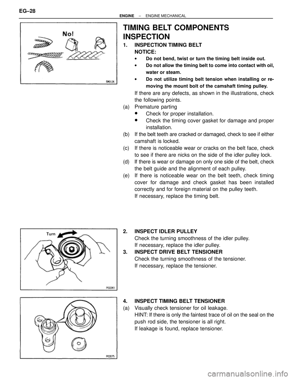
TIMING BELT COMPONENTS
INSPECTION
1. INSPECTION TIMING BELT
NOTICE:
wDo not bend, twist or turn the timing belt inside out.
wDo not allow the timing belt to come into contact with oil,
water or steam.
wDo not utilize timing belt tension when installing or re-
moving the mount bolt of the camshaft timing pulley.
If there are any defects, as shown in the illustrations, check
the following points.
(a) Premature parting
wCheck for proper installation.
wCheck the timing cover gasket for damage and proper
installation.
(b) If the belt teeth are cracked or damaged, check to see if either
camshaft is locked.
(c) If there is noticeable wear or cracks on the belt face, check
to see if there are nicks on the side of the idler pulley lock.
(d) If there is wear or damage on only one side of the belt, check
the belt guide and the alignment of each pulley.
(e) If there is noticeable wear on the belt teeth, check timing
cover for damage and check gasket has been installed
correctly and for foreign material on the pulley teeth.
If necessary, replace the timing belt.
2. INSPECT IDLER PULLEY
Check the turning smoothness of the idler pulley.
If necessary, replace the idler pulley.
3. INSPECT DRIVE BELT TENSIONER
Check the turning smoothness of the tensioner.
If necessary, replace the tensioner.
4. INSPECT TIMING BELT TENSIONER
(a) Visually check tensioner for oil leakage.
HINT: If there is only the faintest trace of oil on the seal on the
push rod side, the tensioner is all right.
If leakage is found, replace tensioner. EG±28
± ENGINEENGINE MECHANICAL