Page 1344 of 2543
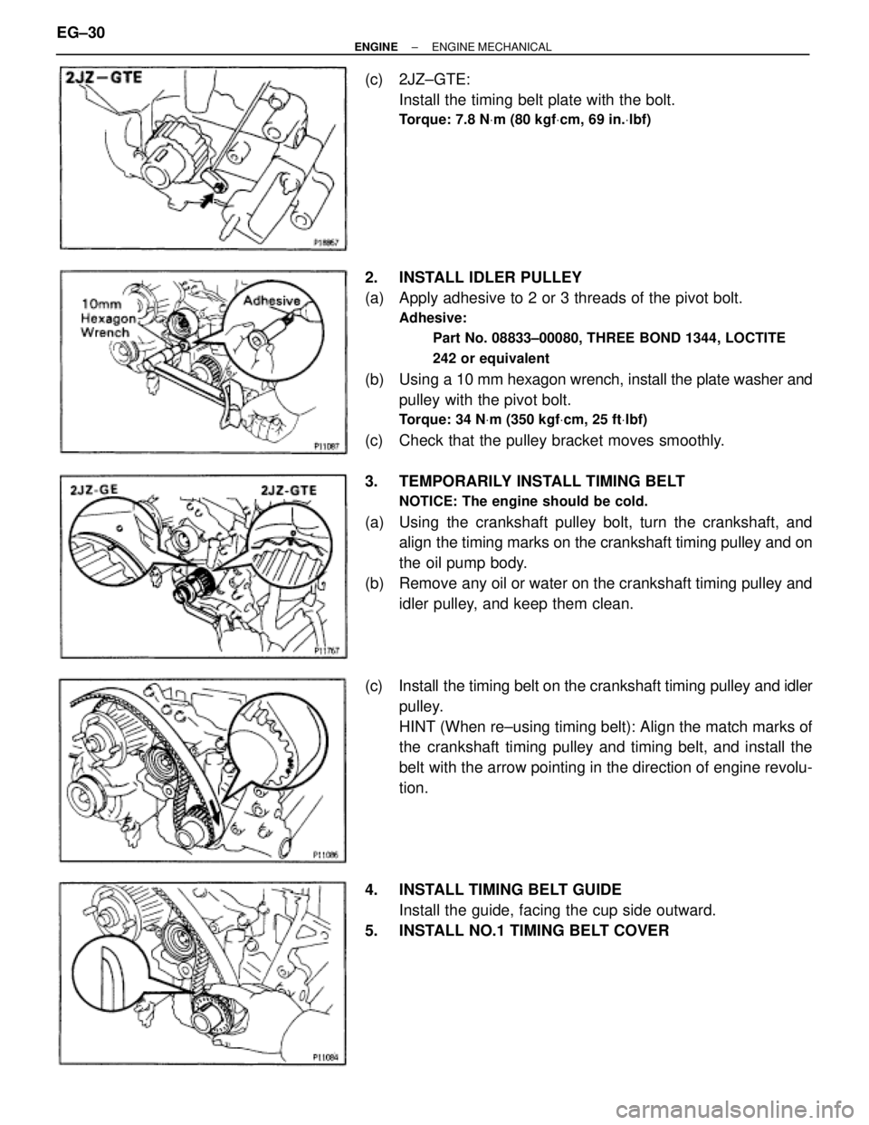
(c) 2JZ±GTE:
Install the timing belt plate with the bolt.
Torque: 7.8 NVm (80 kgfVcm, 69 in.Vlbf)
2. INSTALL IDLER PULLEY
(a) Apply adhesive to 2 or 3 threads of the pivot bolt.
Adhesive:
Part No. 08833±00080, THREE BOND 1344, LOCTITE
242 or equivalent
(b) Using a 10 mm hexagon wrench, install the plate washer and
pulley with the pivot bolt.
Torque: 34 NVm (350 kgfVcm, 25 ftVlbf)
(c) Check that the pulley bracket moves smoothly.
3. TEMPORARILY INSTALL TIMING BELT
NOTICE: The engine should be cold.
(a) Using the crankshaft pulley bolt, turn the crankshaft, and
align the timing marks on the crankshaft timing pulley and on
the oil pump body.
(b) Remove any oil or water on the crankshaft timing pulley and
idler pulley, and keep them clean.
(c) Install the timing belt on the crankshaft timing pulley and idler
pulley.
HINT (When re±using timing belt): Align the match marks of
the crankshaft timing pulley and timing belt, and install the
belt with the arrow pointing in the direction of engine revolu-
tion.
4. INSTALL TIMING BELT GUIDE
Install the guide, facing the cup side outward.
5. INSTALL NO.1 TIMING BELT COVER EG±30
± ENGINEENGINE MECHANICAL
Page 1345 of 2543
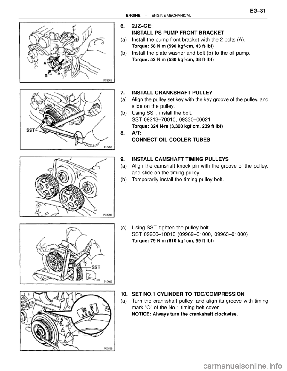
6. 2JZ±GE:
INSTALL PS PUMP FRONT BRACKET
(a) Install the pump front bracket with the 2 bolts (A).
Torque: 58 NVm (590 kgfVcm, 43 ftVlbf)
(b) Install the plate washer and bolt (b) to the oil pump.
Torque: 52 NVm (530 kgfVcm, 38 ftVlbf)
7. INSTALL CRANKSHAFT PULLEY
(a) Align the pulley set key with the key groove of the pulley, and
slide on the pulley.
(b) Using SST, install the bolt.
SST 09213±70010, 09330±00021
Torque: 324 NVm (3,300 kgfVcm, 239 ftVlbf)
8. A/T:
CONNECT OIL COOLER TUBES
9. INSTALL CAMSHAFT TIMING PULLEYS
(a) Align the camshaft knock pin with the groove of the pulley,
and slide on the timing pulley.
(b) Temporarily install the timing pulley bolt.
(c) Using SST, tighten the pulley bolt.
SST 09960±10010 (09962±01000, 09963±01000)
Torque: 79 NVm (810 kgfVcm, 59 ftVlbf)
10. SET NO.1 CYLINDER TO TDC/COMPRESSION
(a) Turn the crankshaft pulley, and align its groove with timing
mark ºOº of the No.1 timing belt cover.
NOTICE: Always turn the crankshaft clockwise.
± ENGINEENGINE MECHANICALEG±31
Page 1346 of 2543
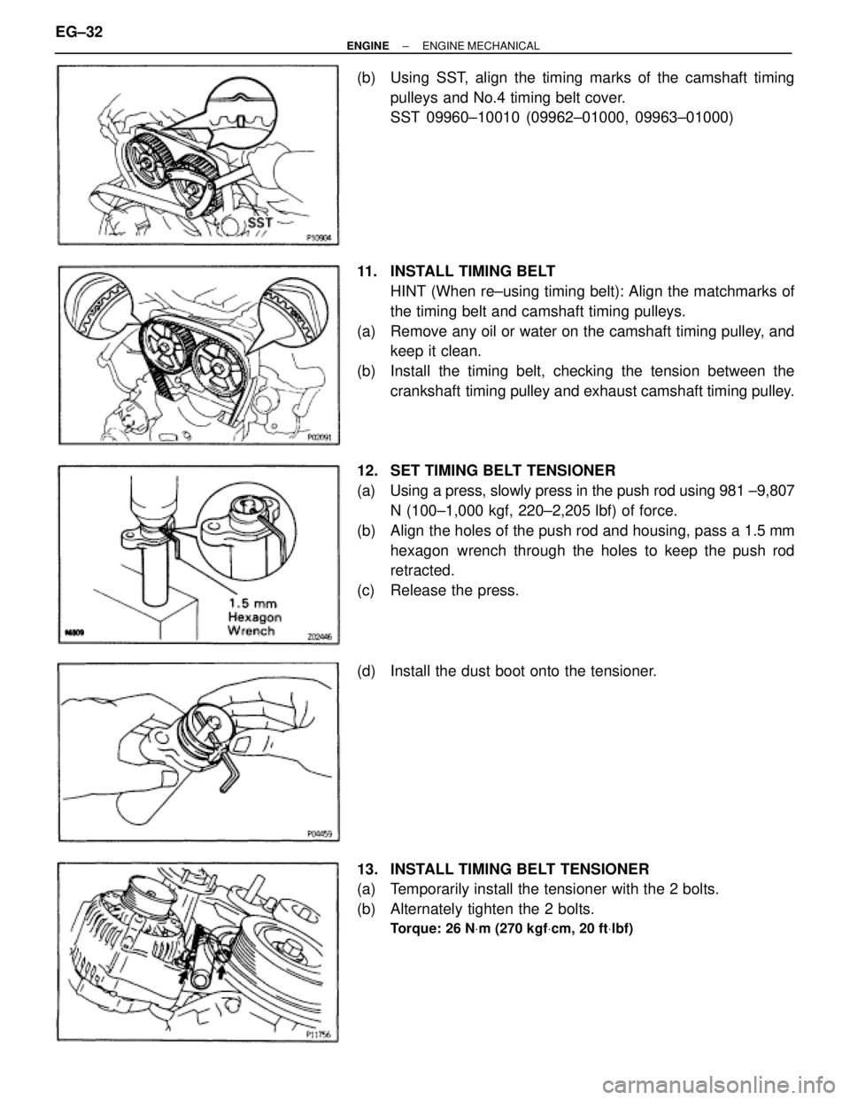
(b) Using SST, align the timing marks of the camshaft timing
pulleys and No.4 timing belt cover.
SST 09960±10010 (09962±01000, 09963±01000)
11. INSTALL TIMING BELT
HINT (When re±using timing belt): Align the matchmarks of
the timing belt and camshaft timing pulleys.
(a) Remove any oil or water on the camshaft timing pulley, and
keep it clean.
(b) Install the timing belt, checking the tension between the
crankshaft timing pulley and exhaust camshaft timing pulley.
12. SET TIMING BELT TENSIONER
(a) Using a press, slowly press in the push rod using 981 ±9,807
N (100±1,000 kgf, 220±2,205 lbf) of force.
(b) Align the holes of the push rod and housing, pass a 1.5 mm
hexagon wrench through the holes to keep the push rod
retracted.
(c) Release the press.
(d) Install the dust boot onto the tensioner.
13. INSTALL TIMING BELT TENSIONER
(a) Temporarily install the tensioner with the 2 bolts.
(b) Alternately tighten the 2 bolts.
Torque: 26 NVm (270 kgfVcm, 20 ftVlbf)
EG±32± ENGINEENGINE MECHANICAL
Page 1356 of 2543
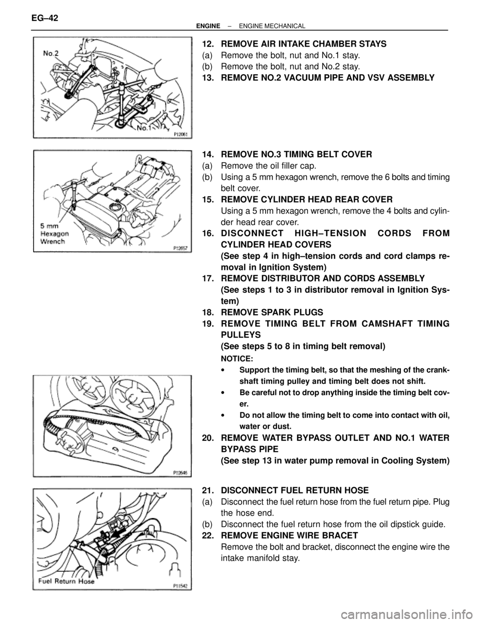
12. REMOVE AIR INTAKE CHAMBER STAYS
(a) Remove the bolt, nut and No.1 stay.
(b) Remove the bolt, nut and No.2 stay.
13. REMOVE NO.2 VACUUM PIPE AND VSV ASSEMBLY
14. REMOVE NO.3 TIMING BELT COVER
(a) Remove the oil filler cap.
(b) Using a 5 mm hexagon wrench, remove the 6 bolts and timing
belt cover.
15. REMOVE CYLINDER HEAD REAR COVER
Using a 5 mm hexagon wrench, remove the 4 bolts and cylin-
der head rear cover.
16. D I S C O N N E C T H I G H ± T E N S I O N C O R D S F R O M
CYLINDER HEAD COVERS
(See step 4 in high±tension cords and cord clamps re-
moval in Ignition System)
17. REMOVE DISTRIBUTOR AND CORDS ASSEMBLY
(See steps 1 to 3 in distributor removal in Ignition Sys-
tem)
18. REMOVE SPARK PLUGS
19. RE MO V E TIMING BE LT FRO M CAMS HAFT TIMING
PULLEYS
(See steps 5 to 8 in timing belt removal)
NOTICE:
wSupport the timing belt, so that the meshing of the crank-
shaft timing pulley and timing belt does not shift.
wBe careful not to drop anything inside the timing belt cov-
er.
wDo not allow the timing belt to come into contact with oil,
water or dust.
20. REMOVE WATER BYPASS OUTLET AND NO.1 WATER
BYPASS PIPE
(See step 13 in water pump removal in Cooling System)
21. DISCONNECT FUEL RETURN HOSE
(a) Disconnect the fuel return hose from the fuel return pipe. Plug
the hose end.
(b) Disconnect the fuel return hose from the oil dipstick guide.
22. REMOVE ENGINE WIRE BRACET
Remove the bolt and bracket, disconnect the engine wire the
intake manifold stay. EG±42
± ENGINEENGINE MECHANICAL
Page 1357 of 2543
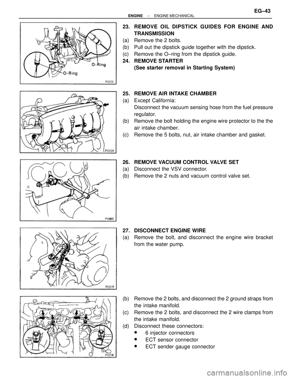
23. REMOVE OIL DIPSTICK GUIDES FOR ENGINE AND
TRANSMISSION
(a) Remove the 2 bolts.
(b) Pull out the dipstick guide together with the dipstick.
(c) Remove the O±ring from the dipstick guide.
24. REMOVE STARTER
(See starter removal in Starting System)
25. REMOVE AIR INTAKE CHAMBER
(a) Except California:
Disconnect the vacuum sensing hose from the fuel pressure
regulator.
(b) Remove the bolt holding the engine wire protector to the the
air intake chamber.
(c) Remove the 5 bolts, nut, air intake chamber and gasket.
26. REMOVE VACUUM CONTROL VALVE SET
(a) Disconnect the VSV connector.
(b) Remove the 2 nuts and vacuum control valve set.
27. DISCONNECT ENGINE WIRE
(a) Remove the bolt, and disconnect the engine wire bracket
from the water pump.
(b) Remove the 2 bolts, and disconnect the 2 ground straps from
the intake manifold.
(c) Remove the 2 bolts, and disconnect the 2 wire clamps from
the intake manifold.
(d) Disconnect these connectors:
w6 injector connectors
wECT sensor connector
wECT sender gauge connector
± ENGINEENGINE MECHANICALEG±43
Page 1359 of 2543
33. REMOVE NO.3, NO.1 AND NO.2 CYLINDER HEAD
COVERS
(a) Remove the PCV valve.
(b) Remove the 4 bolts, 4 nuts and No.3 cylinder head cover.
(c) Remove the 4 bolts, No.1 cylinder head cover and gasket.
(d) Remove the 4 bolts, No.2 cylinder head cover and gasket.
34. REMOVE CAMSHAFT TIMING PULLEYS
Hold the hexagon portion of the camshaft with a wrench, and
remove the pulley mounting bolt and camshaft pulley.
35. REMOVE NO.4 TIMING BELT COVER
Remove the 4 bolts and timing belt cover.
36. REMOVE CAMSHAFTS
(a) Uniformly loosen and remove the 4 No.1 bearing cap bolts.
(b) Using a screwdriver, pry out the 2 No.1 camshaft bearing
caps and oil seals.
NOTICE: Be careful not to damage the cap. Tape the screwdriv-
er tip.
± ENGINEENGINE MECHANICALEG±45
Page 1363 of 2543
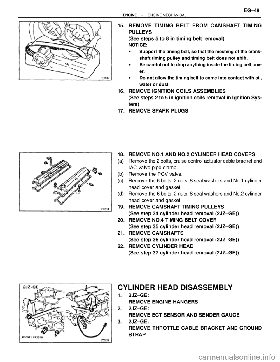
15. REMOVE TIMING BELT FROM CAMSHAFT TIMING
PULLEYS
(See steps 5 to 8 in timing belt removal)
NOTICE:
wSupport the timing belt, so that the meshing of the crank-
shaft timing pulley and timing belt does not shift.
wBe careful not to drop anything inside the timing belt cov-
er.
wDo not allow the timing belt to come into contact with oil,
water or dust.
16. REMOVE IGNITION COILS ASSEMBLIES
(See steps 2 to 5 in ignition coils removal in Ignition Sys-
tem)
17. REMOVE SPARK PLUGS
18. REMOVE NO.1 AND NO.2 CYLINDER HEAD COVERS
(a) Remove the 2 bolts, cruise control actuator cable bracket and
IAC valve pipe clamp.
(b) Remove the PCV valve.
(c) Remove the 6 bolts, 2 nuts, 8 seal washers and No.1 cylinder
head cover and gasket.
(d) Remove the 6 bolts, 2 nuts, 8 seal washers and No.2 cylinder
head cover and gasket.
19. REMOVE CAMSHAFT TIMING PULLEYS
(See step 34 cylinder head removal (2JZ±GE))
20. REMOVE NO.4 TIMING BELT COVER
(See step 35 cylinder head removal (2JZ±GE))
21. REMOVE CAMSHAFTS
(See step 36 cylinder head removal (2JZ±GE))
22. REMOVE CYLINDER HEAD
(See step 37 cylinder head removal (2JZ±GE))
CYLINDER HEAD DISASSEMBLY
1. 2JZ±GE:
REMOVE ENGINE HANGERS
2. 2JZ±GE:
REMOVE ECT SENSOR AND SENDER GAUGE
3. 2JZ±GE:
REMOVE THROTTLE CABLE BRACKET AND GROUND
STRAP
± ENGINEENGINE MECHANICALEG±49
Page 1364 of 2543
4. 2JZ±GTE:
REMOVE ENGINE HANGERS AND GROUND STRAP
5. 2JZ±GTE:
REMOVE CAMSHAFT POSITION SENSORS
6. REMOVE EGR COOLER
7. REMOVE VALVE LIFTERS AND SHIMS
HINT: Store the valve lifters and shims in correct order.
8. REMOVE VALVES
(a) Using SST, compress the valve spring and remove the 2
keepers.
SST 09202±70010
(b) Remove the spring retainer, valve spring, valve and spring
seat.
HINT: Store the valves, valve springs, spring seats and spring
retainers in correct order.
(c) Using needle±nose pliers, remove the oil seal.
CYLINDER HEAD COMPONENTS
INSPECTION AND REPAIR
1. CLEAN TOP SURFACES OF PISTONS AND CYLINDER
BLOCK
(a) Turn the crankshaft, and bring each piston to top dead center
(TDC). Using a gasket scraper, remove all the carbon from
the piston top surface. EG±50
± ENGINEENGINE MECHANICAL