Page 1412 of 2543
PREPARATION FOR DISASSEMBLY
1. M/T:
REMOVE FLYWHEEL
2. A/T:
REMOVE DRIVE PLATE
3. INSTALL ENGINE TO ENGINE STAND FOR
DISASSEMBLY
4. REMOVE GENERATOR
5. REMOVE TIMING BELT AND PULLEYS
(See timing belt removal)
6. REMOVE CYLINDER HEAD
(See cylinder head removal)
7. REMOVE OIL FILTER
(See oil and filter replacement in Lubrication System)
8. 2JZ±GTE:
REMOVE OIL COOLER
(See oil cooler removal in Lubrication System)
9. REMOVE NO.2 WATER BYPASS PIPE
(a) 2JZ±GE:
Remove the bolt, 2 nuts, water bypass pipe and gasket.
(b) 2JZ±GTE:
Remove the 2 bolts, 2 nuts, water bypass pipe and gasket.
10. REMOVE OIL FILTER BRACKET
Remove the union bolt, gasket, oil filter bracket and O ±ring.
11. REMOVE LH ENGINE MOUNTING BRACKET AND
INSULATOR ASSEMBLY
12. REMOVE FUEL PIPE SUPPORT EG±98
± ENGINEENGINE MECHANICAL
Page 1436 of 2543

8. INSTALL FUEL PIPE SUPPORT
Torque: 14 NVm (145 kgfVcm, 10 ftVlbf)
9. INSTALL LH ENGINE MOUNTING BRACKET AND
INSULATOR ASSEMBLY
HINT: LH mounting bracket is marked ºA u INº.
Torque: 58 NVm (590 kgfVcm, 43 ftVlbf)
10. INSTALL OIL FILTER BRACKET
(a) Check and clean the oil filter bracket installation.
(b) Place a new O±ring in position on the oil filter bracket.
(c) Apply clean engine oil to the O±ring.
(d) Install a new gasket to the union bolt.
(e) Install the oil filter braket with the union bolt.
Torque: 88 NVm (900 kgfVcm, 65 ftVlbf)
11. INSTALL NO.2 WATER BYPASS PIPE
(a) Install a new gasket to the water pump.
(b) 2JZ±GE:
Install the water bypass pipe with the bolt and 2 nuts.
Torque: 21 NVm (210 kgfVcm, 15 ftVlbf)
(c) 2JZ±GTE:
Install the water bypass pipe with the 2 bolts and 2 nuts.
Torque: 21 NVm (210 kgfVcm, 15 ftVlbf)
12. 2JZ±GTE:
INSTALL OIL COOLER
(See oil cooler installation in Lubrication System)
13. INSTALL OIL FILTER
(See oil and filter replacement in Lubrication System)
14. INSTALL CYLINDER HEAD
(See cylinder head installation)
15. INSTALL TIMING PULLEYS AND BELT
(See timing belt installation)
16. INSTALL GENERATOR
(See generator installation in Charging System)
17. REMOVE ENGINE STAND FROM ENGINE
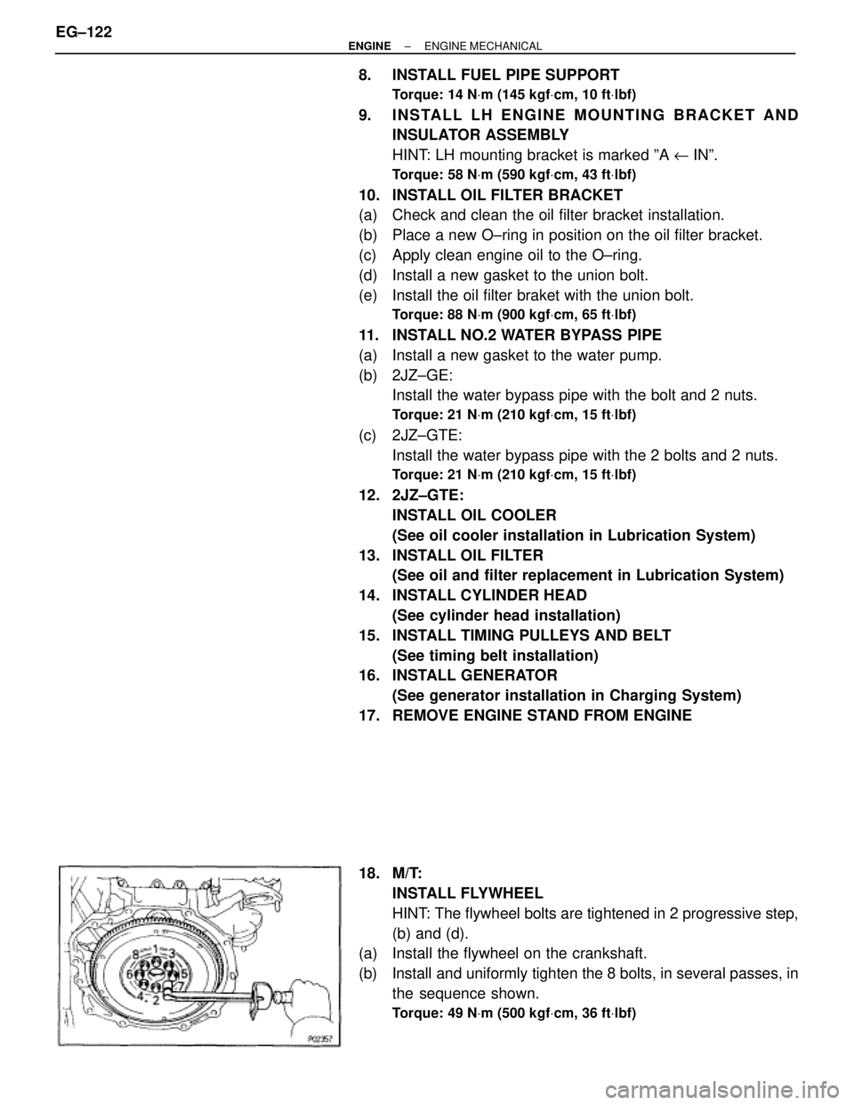
18. M/T:
INSTALL FLYWHEEL
HINT: The flywheel bolts are tightened in 2 progressive step,
(b) and (d).
(a) Install the flywheel on the crankshaft.
(b) Install and uniformly tighten the 8 bolts, in several passes, in
the sequence shown.
Torque: 49 NVm (500 kgfVcm, 36 ftVlbf)
EG±122± ENGINEENGINE MECHANICAL
Page 1437 of 2543
(c) Mark the flywheel bolt with paint.
(d) Retighten the flywheel bolts by an additional 90°.
(e) Check that the painted mark is now at a 90° angle to (d).
19. A/T:
INSTALL DRIVE PLATE
(a) Install the front spacer, drive plate and rear plate on the
crankshaft.
Adhesive:
Part No. 08833±00070, THREE BOND 1324 or equivalent
(b) Apply adhesive to 2 or 3 threads of the mounting bolt end.
(c) Install and uniformly tighten the 8 bolts, in several passes, in
the sequence shown.
Torque: 83 NVm (850 kgfVcm, 61 ftVlbf)
± ENGINEENGINE MECHANICALEG±123
Page 1438 of 2543

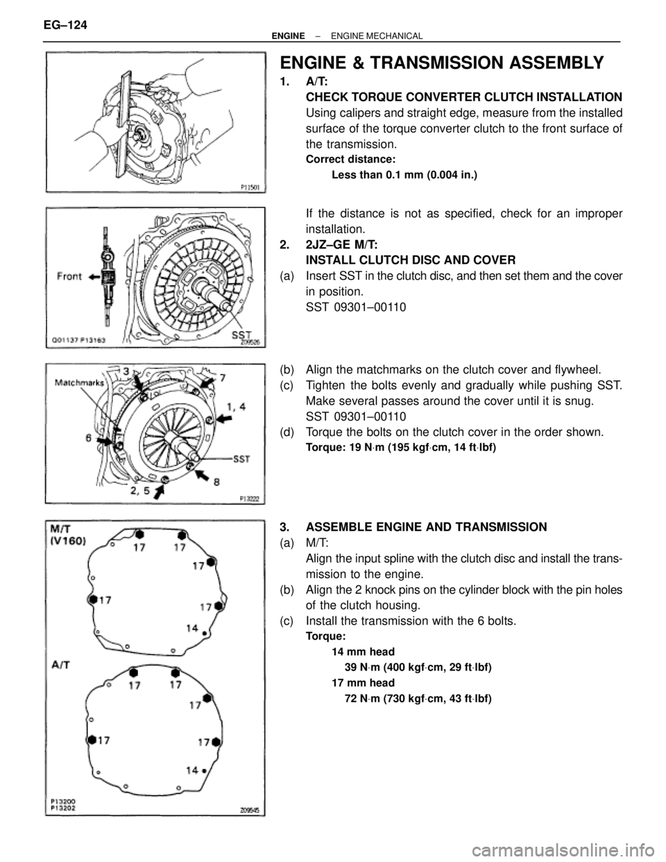
ENGINE & TRANSMISSION ASSEMBLY
1. A/T:
CHECK TORQUE CONVERTER CLUTCH INSTALLATION
Using calipers and straight edge, measure from the installed
surface of the torque converter clutch to the front surface of
the transmission.
Correct distance:
Less than 0.1 mm (0.004 in.)
If the distance is not as specified, check for an improper
installation.
2. 2JZ±GE M/T:
INSTALL CLUTCH DISC AND COVER
(a) Insert SST in the clutch disc, and then set them and the cover
in position.
SST 09301±00110
(b) Align the matchmarks on the clutch cover and flywheel.
(c) Tighten the bolts evenly and gradually while pushing SST.
Make several passes around the cover until it is snug.
SST 09301±00110
(d) Torque the bolts on the clutch cover in the order shown.
Torque: 19 NVm (195 kgfVcm, 14 ftVlbf)
3. ASSEMBLE ENGINE AND TRANSMISSION
(a) M/T:
Align the input spline with the clutch disc and install the trans-
mission to the engine.
(b) Align the 2 knock pins on the cylinder block with the pin holes
of the clutch housing.
(c) Install the transmission with the 6 bolts.
Torque:
14 mm head
39 NVm (400 kgfVcm, 29 ftVlbf)
17 mm head
72 NVm (730 kgfVcm, 43 ftVlbf)
EG±124± ENGINEENGINE MECHANICAL
Page 1453 of 2543

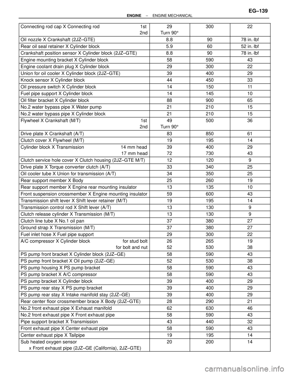
������������������� �������������������Connecting rod cap X Connecting rod 1st
2nd������� �������29
Turn 905������ ������300������� �������22
������������������� �������������������
Oil nozzle X Crankshaft (2JZ±GTE)
������� �������
8.8
������ ������
90
������� �������
78 in.Vlbf������������������� �������������������Rear oil seal retainer X Cylinder block������� �������5.9������ ������60������� �������52 in.Vlbf������������������� �������������������Crankshaft position sensor X Cylinder block (2JZ±GTE)������� �������8.8������ ������90������� �������78 in.Vlbf������������������� �������������������Engine mounting bracket X Cylinder block������� �������58������ ������590������� �������43������������������� �������������������Engine coolant drain plug X Cylinder block������� �������29������ ������300������� �������22������������������� �������������������Union for oil cooler X Cylinder block (2JZ±GTE)������� �������39������ ������400������� �������29
������������������� �������������������Knock sensor X Cylinder block������� �������44������ ������450������� �������33
������������������� �������������������Oil pressure switch X Cylinder block������� �������14������ ������150������� �������11
������������������� �������������������Fuel pipe support X Cylinder block������� �������14������ ������145������� �������10
������������������� �������������������Oil filter bracket X Cylinder block������� �������88������ ������900������� �������65
������������������� �������������������No.2 water bypass pipe X Water pump������� �������21������ ������210������� �������15
������������������� �������������������No.2 water bypass pipe X Cylinder block������� �������21������ ������210������� �������15
������������������� �������������������Flywheel X Crankshaft (M/T) 1st
2nd������� �������49
Turn 905������ ������500������� �������36
������������������� �������������������Drive plate X Crankshaft (A/T)������� �������83������ ������850������� �������61������������������� �������������������Clutch cover X Flywheel (M/T)������� �������19������ ������195������� �������14������������������� �
������������������ �������������������Cylinder block X Transmission 14 mm head
17 mm head������� �
������ �������39
72������ �
����� ������400
730������� �
������ �������29
43
������������������� �������������������Clutch service hole cover X Clutch housing (2JZ±GTE M/T)������� �������12������ ������120������� �������9
������������������� �������������������Drive plate X Torque converter clutch (A/T)������� �������33������ ������340������� �������25
������������������� �������������������Oil cooler tube X Union for transmission (A/T)������� �������34������ ������350������� �������25
������������������� �������������������Rear support member X Body������� �������25������ ������260������� �������19
������������������� �������������������Rear support member X Engine rear mounting insulator������� �������13������ ������135������� �������10
������������������� �������������������Front suspension crossmember X Engine mounting insulator������� �������59������ ������600������� �������43
������������������� �������������������Transmission shift lever X Shift lever retainer (M/T)������� �������19������ ������195������� �������14
������������������� �������������������Transmission control rod X Shift lever (A/T)������� �������13������ ������130������� �������9
�������������������Clutch release cylinder X Transmission (M/T)�������13������130�������9������������������� �������������������
Clutch line tube X No.1 oil pan
������� �������
37
������ ������
380
������� �������
27������������������� �������������������Ground strap X Transmission (M/T)������� �������37������ ������380������� �������27������������������� �������������������Fuel inlet hose X Fuel pipe support������� �������29������ ������300������� �������22������������������� �
������������������ �������������������A/C compressor X Cylinder block for stud bolt
for bolt and nut������� �
������ �������26
52������ �
����� ������265
530������� �
������ �������19
38
������������������� �������������������PS pump front bracket X Cylinder block (2JZ±GE)������� �������58������ ������590������� �������43
������������������� �������������������PS pump front bracket X Oil pump (2JZ±GE)������� �������52������ ������530������� �������38
������������������� �������������������PS pump housing X PS pump bracket������� �������58������ ������590������� �������43
������������������� �������������������PS pump bracket X A/C compressor������� �������58������ ������590������� �������43
������������������� �������������������PS pump bracket X Cylinder block������� �������39������ ������400������� �������29
������������������� �������������������PS pump rear stay X PS pump bracket������� �������39������ ������400������� �������29
������������������� �������������������PS pump rear stay X Intake manifold stay (2JZ±GE)������� �������39������ ������400������� �������29
������������������� �������������������Rear center floor crossmember brace X Body (2JZ±GTE)������� �������28������ ������290������� �������21
�������������������No.2 front exhaust pipe X Exhaust manifold�������62������630�������46������������������� �������������������No.2 front exhaust pipe X Front exhaust pipe������� �������58������ ������590������� �������43������������������� �������������������Pipe support bracket X Transmission������� �������43������ ������440������� �������32������������������� �������������������Front exhaust pipe X Center exhaust pipe������� �������58������ ������590������� �������43������������������� �������������������Center exhaust pipe X Tailpipe������� �������19������ ������195������� �������14������������������� �
������������������ �������������������
Sub heated oxygen sensor
x Front exhaust pipe (2JZ±GE (California), 2JZ±GTE)������� �
������ �������
20������ �
����� ������
200������� �
������ �������
14
± ENGINEENGINE MECHANICALEG±139
Page 1485 of 2543
COMPONENTS FOR REMOVAL AND
INSTALLATION
FUEL PUMP REMOVAL
CAUTION: Do not smoke or work near an open flame when
working on the fuel pump.
1. TAKE OUT FLOOR CARPET
2. REMOVE SPARE WHEEL COVER
3. REMOVE SPARE WHEEL
4. REMOVE SERVICE HOLE COVER
± ENGINESFI SYSTEM (2JZ±GE)EG±195
Page 1489 of 2543
(g) Install the retainer clamp.
(h) Connect the connector and hoses to the fuel pump bracket:
wFuel pump connector
wFuel outlet hose
Connect the outlet hose with 2 new gaskets and the union
bolt.
Torque: 29 NVm (300 kgfVcm, 22 ftVlbf)
wFuel return hose
wFuel breather hose
2. REMOVE SERVICE HOLE COVER
3. REMOVE SPARE WHEEL
4. REMOVE SPARE WHEEL COVER
5. TAKE OUT FLOOR CARPET
6. CHECK FOR FUEL LEAKS
(See item 5 in fuel system in precaution)
± ENGINESFI SYSTEM (2JZ±GE)EG±199
Page 1556 of 2543
COMPONENTS FOR REMOVAL AND
INSTALLATION
FUEL PUMP REMOVAL
CAUTION: Do not smoke or work near an open flame when
working on the fuel pump.
1. TAKE OUT FLOOR CARPET
2. REMOVE SPARE WHEEL COVER
3. REMOVE SPARE WHEEL
4. REMOVE SERVICE HOLE COVER EG±266
± ENGINESFI SYSTEM (2JZ±GTE)