Page 1560 of 2543
(e) Temporarily install the retainer.
(f) Using SST, tighten the retainer until the arrow mark on
retainer is within the lines on the fuel tank.
SST 09808±14010
(g) Check that the arrow marks of the fuel pump bracket and fuel
tank are aligned.
(h) Install the retainer clamp.
(i) Connect the connector and hoses to the fuel pump bracket:
wFuel pump connector
wFuel outlet hose
Connect the outlet hose with 2 new gaskets and the union
bolt.
Torque: 29 NVm (300 kgfVcm, 22 ftVlbf)
wFuel return hose
wFuel breather hose
2. INSTALL SERVICE HOLE COVER
3. INSTALL SPARE WHEEL
4. INSTALL SPARE WHEEL COVER
5. INSTALL FLOOR CARPET
6. CHECK FOR FUEL LEAKS
(See item 5 in fuel system in precaution) EG±270
± ENGINESFI SYSTEM (2JZ±GTE)
Page 1633 of 2543
PRECAUTION
wCare must be taken to replace parts properly because they could affect the
performance of the steering system and result in a driving hazard.
wThe steering wheel pad has an SRS (Supplemental Restraint System) airbag built in,
so take all due precautions when handling it. For more details, see the RS section.
TROUBLESHOOTING
Use the table below to help you find the cause of the problem. The numbers indicate the priority of the likely
cause of the problem. Check each part in order. If necessary, repair or replace these parts.
SA±3SA±4SR±7SA±27SR±49SR±47SA±16
Tires (improperly inflated)Steering column (Binding)Suspension arm ball joints (Worn)Steering system joints (Worn)Drive belt (Loose)Fluid level (Low)Front wheel alignment (Incorrect)Electronic controlSolenoid valveSteering gear housingSliding yoke (Worn)Front wheel bearing (Worn)
Hard steering
Abnormal noise
Excessive play
Poor return
See page
Parts
Name
Trouble
SA±30
SR±2± STEERINGTROUBLESHOOTING
Page 1636 of 2543
(09957±04010)
09950±40010
(09958±04010)
09950±50010
(09951±05010)
(09952±05010)
(09953±05020)
(09954±05020)
09960±10010
Puller B Set
Attachment
Holder
Puller C Set
Slide Arm
Hanger 150
Center Bolt 150
Variable Pin Wrench Set
Claw No.2
Vane pump pulley
Main shaft assembly
Main shaft assembly
RECOMMENDED TOOLS
Total preload
Steering wheel pad
Compression spring
Snap Ring No.1 Expander
TOYOTA Electrical Tester Set
Torx Socket T30
Torque Wrench (30 kgf�cm)09025±00010
09042±00010
09082±00050
09905±00012
± STEERINGPREPARATIONSR±5
Page 1638 of 2543

ON±VEHICLE INSPECTION
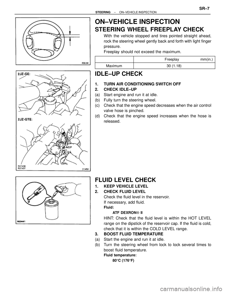
STEERING WHEEL FREEPLAY CHECK
With the vehicle stopped and tires pointed straight ahead,
rock the steering wheel gently back and forth with light finger
pressure.
Freeplay should not exceed the maximum.
�������� �
�������
��������������� �
�������������� Freeplay mm(in.)�������� ��������
Maximum30 (1 18)�������� ��������Maximum30 (1.18)
IDLE±UP CHECK
1. TURN AIR CONDITIONING SWITCH OFF
2. CHECK IDLE±UP
(a) Start engine and run it at idle.
(b) Fully turn the steering wheel.
(c) Check that the engine speed decreases when the air control
valve hose is pinched.
(d) Check that the engine speed increases when the hose is
released.
FLUID LEVEL CHECK
1. KEEP VEHICLE LEVEL
2. CHECK FLUID LEVEL
Check the fluid level in the reservoir.
If necessary, add fluid.
Fluid:
ATF DEXRON[ II
HINT: Check that the fluid level is within the HOT LEVEL
range on the dipstick of the reservoir cap. If the fluid is cold,
check that it is within the COLD LEVEL range.
3. BOOST FLUID TEMPERATURE
(a) Start the engine and run it at idle.
(b) Turn the steering wheel from lock to lock several times to
boost fluid temperature.
Fluid temperature:
805C (1765F)
± STEERINGON±VEHICLE INSPECTIONSR±7
Page 1639 of 2543

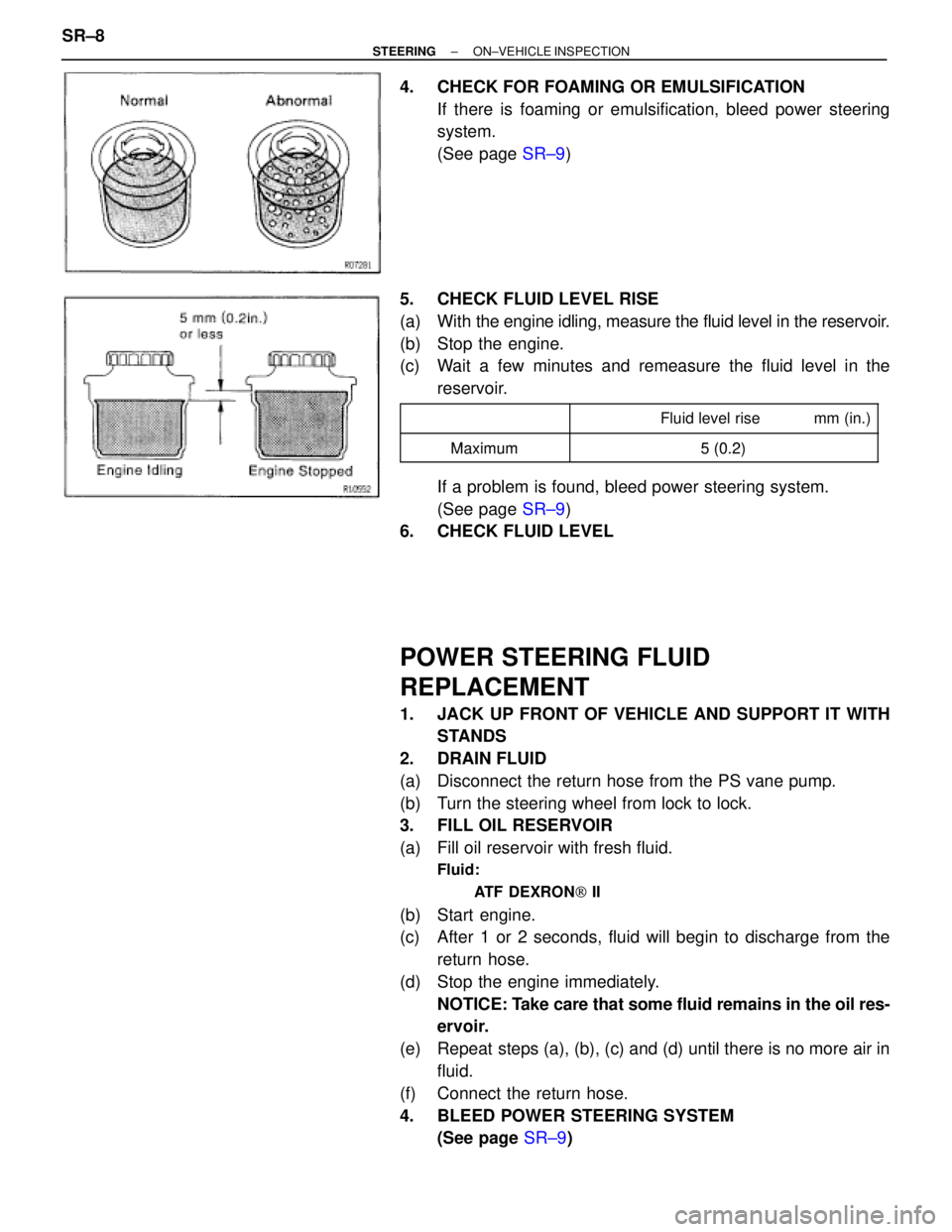
4. CHECK FOR FOAMING OR EMULSIFICATION
If there is foaming or emulsification, bleed power steering
system.
(See page SR±9)
5. CHECK FLUID LEVEL RISE
(a) With the engine idling, measure the fluid level in the reservoir.
(b) Stop the engine.
(c) Wait a few minutes and remeasure the fluid level in the
reservoir.
�������� �
������� ��������
�������������� �
������������� �������������� Fluid level rise mm (in.)
��������Maximum5(02)�������� ��������Maximum5 (0.2)
If a problem is found, bleed power steering system.
(See page SR±9)
6. CHECK FLUID LEVEL
POWER STEERING FLUID
REPLACEMENT
1. JACK UP FRONT OF VEHICLE AND SUPPORT IT WITH
STANDS
2. DRAIN FLUID
(a) Disconnect the return hose from the PS vane pump.
(b) Turn the steering wheel from lock to lock.
3. FILL OIL RESERVOIR
(a) Fill oil reservoir with fresh fluid.
Fluid:
ATF DEXRON[ II
(b) Start engine.
(c) After 1 or 2 seconds, fluid will begin to discharge from the
return hose.
(d) Stop the engine immediately.
NOTICE: Take care that some fluid remains in the oil res-
ervoir.
(e) Repeat steps (a), (b), (c) and (d) until there is no more air in
fluid.
(f) Connect the return hose.
4. BLEED POWER STEERING SYSTEM
(See page SR±9) SR±8
± STEERINGON±VEHICLE INSPECTION
Page 1640 of 2543
POWER STEERING SYSTEM BLEEDING
1. JACK UP FRONT OF VEHICLE AND SUPPORT IT WITH
STANDS
2. TURN STEERING WHEEL
With the engine stopped, turn the steering slowly from lock
to lock several times.
NOTICE: Take care that some fluid remains in the oil res-
ervoir.
3. LOWER VEHICLE
4. START ENGINE
Run the engine at idle for a few minutes.
5. TURN STEERING WHEEL
(a) With the engine at idling, turn the wheel to left or right full lock
and keep it there for 2±3 seconds, then turn the wheel to the
opposite full lock and keep it there for 2±3 seconds.
(b) Repeat (a) several times.
6. STOP ENGINE
7. CHECK FOR FOAMING OR EMULSIFICATION
If the system has to be bled twice specifically because of
foaming or emulsification, check for fluid leaks in the system.
8. CHECK FLUID LEVEL
(See page SR±7)
± STEERINGON±VEHICLE INSPECTIONSR±9
Page 1641 of 2543
FLUID PRESSURE CHECK
1. CONNECT OIL PRESSURE GAUGE
(a) Disconnect the pressure feed tube from the PS vane pump.
(See page SR±26)
(b) Connect the gauge over a new gasket, as shown below.
NOTICE: Check that the valve of the gauge is in the open
position.
2. BLEED POWER STEERING SYSTEM
(See page SR±9)
3. BOOST FLUID TEMPERATURE
(a) Start the engine and run it at idle.
(b) Turn the steering wheel from lock to lock several times to
boost fluid temperature.
Fluid temperature:
805C (1765F)
4. CHECK FLUID PRESSURE READING WITH VALVE
CLOSED
With the engine idling, close the oil pressure gauge valve and
observe the reading on the gauge.
������� ���������������������� ��������������� Fluid pressure kPa (kgf/cm2, psi)
������� �������Minimum7 355 (75 1 067)
�������
Minimum7,355 (75, 1,067)
NOTICE:
wDo not keep the valve closed for more than 10
seconds.
wDo not let the fluid temperature become too high. SR±10
± STEERINGON±VEHICLE INSPECTION
Page 1642 of 2543

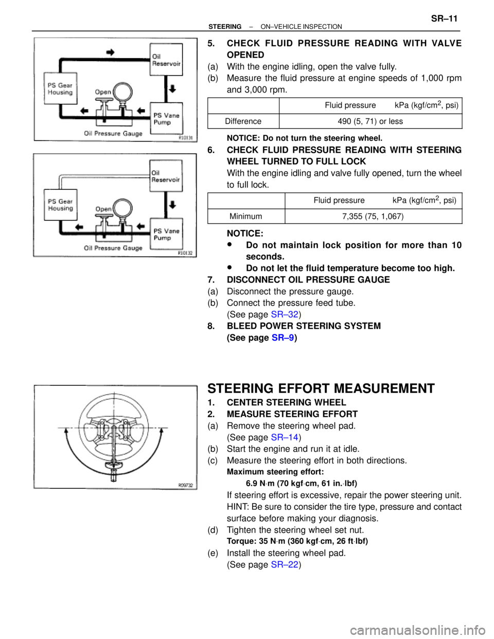
5. CHECK FLUID PRESSURE READING WITH VALVE
OPENED
(a) With the engine idling, open the valve fully.
(b) Measure the fluid pressure at engine speeds of 1,000 rpm
and 3,000 rpm.
������� �
������ �������
���������������� �
��������������� ����������������Fluid pressure kPa (kgf/cm2, psi)
������� �������Difference���������������� ����������������490 (5, 71) or less
NOTICE: Do not turn the steering wheel.
6. CHECK FLUID PRESSURE READING WITH STEERING
WHEEL TURNED TO FULL LOCK
With the engine idling and valve fully opened, turn the wheel
to full lock.
������� ����������������������� ���������������� Fluid pressure kPa (kgf/cm2, psi)������� �
������ �������Minimum
���������������� �
��������������� ����������������7,355 (75, 1,067)
NOTICE:
wDo not maintain lock position for more than 10
seconds.
wDo not let the fluid temperature become too high.
7. DISCONNECT OIL PRESSURE GAUGE
(a) Disconnect the pressure gauge.
(b) Connect the pressure feed tube.
(See page SR±32)
8. BLEED POWER STEERING SYSTEM
(See page SR±9)
STEERING EFFORT MEASUREMENT
1. CENTER STEERING WHEEL
2. MEASURE STEERING EFFORT
(a) Remove the steering wheel pad.
(See page SR±14)
(b) Start the engine and run it at idle.
(c) Measure the steering effort in both directions.
Maximum steering effort:
6.9 NVm (70 kgfVcm, 61 in.Vlbf)
If steering effort is excessive, repair the power steering unit.
HINT: Be sure to consider the tire type, pressure and contact
surface before making your diagnosis.
(d) Tighten the steering wheel set nut.
Torque: 35 NVm (360 kgfVcm, 26 ftVlbf)
(e) Install the steering wheel pad.
(See page SR±22)
± STEERINGON±VEHICLE INSPECTIONSR±11