TURBOCHARGER COMPONENTS
INSPECTION
Turbochargers
1. INSPECT TURBINE SHAFT ROTATION
Grasp the edge of the turbine wheel and turn it. Check that
the impeller wheel turns smoothly.
If the impeller wheel does not turn or if it turns with a drag, re-
place the turbocharger assembly.
2. INSPECT AXIAL PLAY OF TURBINE SHAFT
(a) Using a dial indicator, insert the needle of the dial indicator
into the air tube side.
(b) Move the turbine shaft in an axial direction, measure the axial
play of the turbine shaft.
Maximum axial play:
0.110 mm (0.0045 in.)
If the axial play is greater than maximum, replace the turbo-
charger assembly.
3. INSPECT RADIAL PLAY OF TURBINE SHAFT
(a) Using a dial indicator, insert the needle of the dial indicator
into the oil outlet hole and set it in the center of the turbine
shaft.
(b) Move the turbine shaft in a radial direction, measure the
radial play of the turbine shaft.
Maximum radial play:
0.162 mm (0.0064 in.)
If the axial play is greater than maximum, replace the turbo-
charger assembly.
4. INSPECT WASTE GATE VALVE OPERATION
(a) Disconnect the actuator air hose from the housing, and plug
the hose end.
(b) Using SST, apply approx. 120 kPa (1.22 kgf/cm
2, 17.4 psi) of
pressure to the actuator.
SST 09992±00241
(c) Move the actuator push rod, and check that the waste gate
valve is open.
If operation is not as specified, replace the No.1 turbocharger
assembly.
NOTICE: Never apply more than 187 kPa (1.91 kgf/cm2, 27.2
psi) of pressure to the actuator.
(d) Reconnect the actuator air hose to the housing. EG±158
± ENGINETURBOCHARGER SYSTEM (2JZ±GTE)
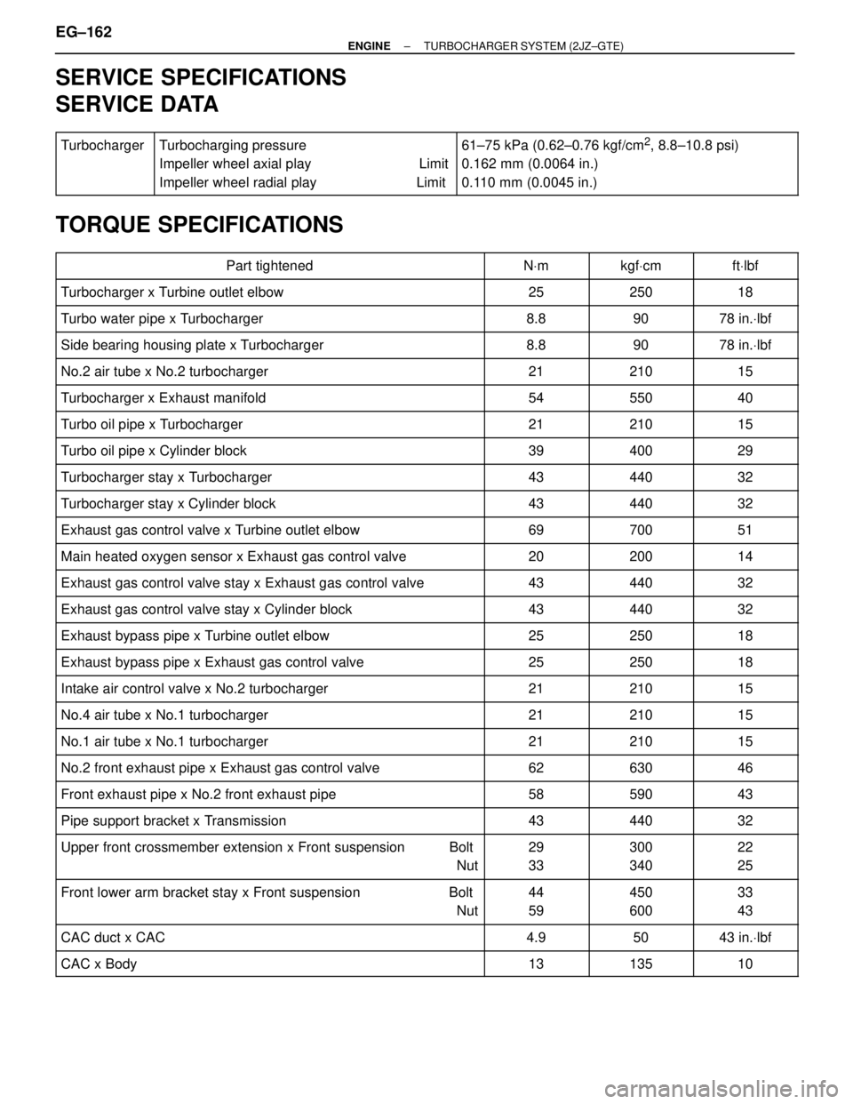
SERVICE SPECIFICATIONS
SERVICE DATA
������ �
����� �
����� ������
Turbocharger��������������� �
�������������� �
�������������� ���������������
Turbocharging pressure
Impeller wheel axial play Limit
Impeller wheel radial play Limit����������������� �
���������������� �
���������������� �����������������
61±75 kPa (0.62±0.76 kgf/cm2, 8.8±10.8 psi)
0.162 mm (0.0064 in.)
0.110 mm (0.0045 in.)
TORQUE SPECIFICATIONS
��������������������� �
�������������������� ���������������������Part tightened������ �
����� ������NVm������ �
����� ������kgfVcm������ �
����� ������ftVlbf
��������������������� ���������������������Turbocharger x Turbine outlet elbow������ ������25������ ������250������ ������18
��������������������� ���������������������Turbo water pipe x Turbocharger������ ������8.8������ ������90������ ������78 in.Vlbf
��������������������� ���������������������Side bearing housing plate x Turbocharger������ ������8.8������ ������90������ ������78 in.Vlbf
��������������������� ���������������������No.2 air tube x No.2 turbocharger������ ������21������ ������210������ ������15��������������������� �
�������������������� ���������������������Turbocharger x Exhaust manifold
������ �
����� ������54
������ �
����� ������550
������ �
����� ������40
��������������������� ���������������������Turbo oil pipe x Turbocharger������ ������21������ ������210������ ������15
��������������������� ���������������������Turbo oil pipe x Cylinder block������ ������39������ ������400������ ������29
��������������������� ���������������������Turbocharger stay x Turbocharger������ ������43������ ������440������ ������32��������������������� �
�������������������� ���������������������Turbocharger stay x Cylinder block
������ �
����� ������43
������ �
����� ������440
������ �
����� ������32
��������������������� ���������������������Exhaust gas control valve x Turbine outlet elbow������ ������69������ ������700������ ������51
��������������������� ���������������������Main heated oxygen sensor x Exhaust gas control valve������ ������20������ ������200������ ������14
��������������������� ���������������������Exhaust gas control valve stay x Exhaust gas control valve������ ������43������ ������440������ ������32��������������������� �
�������������������� ���������������������Exhaust gas control valve stay x Cylinder block
������ �
����� ������43
������ �
����� ������440
������ �
����� ������32
��������������������� ���������������������Exhaust bypass pipe x Turbine outlet elbow������ ������25������ ������250������ ������18
��������������������� ���������������������Exhaust bypass pipe x Exhaust gas control valve������ ������25������ ������250������ ������18
��������������������� ���������������������Intake air control valve x No.2 turbocharger������ ������21������ ������210������ ������15��������������������� �
��������������������No.4 air tube x No.1 turbocharger������ �
�����21������ �
�����210������ �
�����15��������������������� �
�������������������� ���������������������No.1 air tube x No.1 turbocharger
������ �
����� ������21
������ �
����� ������210
������ �
����� ������15
��������������������� ���������������������No.2 front exhaust pipe x Exhaust gas control valve������ ������62������ ������630������ ������46
��������������������� ���������������������Front exhaust pipe x No.2 front exhaust pipe������ ������58������ ������590������ ������43
��������������������� ���������������������Pipe support bracket x Transmission������ ������43������ ������440������ ������32��������������������� �
�������������������� �
�������������������� ���������������������
Upper front crossmember extension x Front suspension Bolt
Nut
������ �
����� �
����� ������
29
33
������ �
����� �
����� ������
300
340
������ �
����� �
����� ������
22
25
��������������������� �
�������������������� ���������������������
Front lower arm bracket stay x Front suspension Bolt
Nut������ �
����� ������
44
59������ �
����� ������
450
600������ �
����� ������
33
43
��������������������� ���������������������CAC duct x CAC������ ������4.9������ ������50������ ������43 in.Vlbf
��������������������� ���������������������CAC x Body������ ������13������ ������135������ ������10
EG±162± ENGINETURBOCHARGER SYSTEM (2JZ±GTE)