Page 1492 of 2248
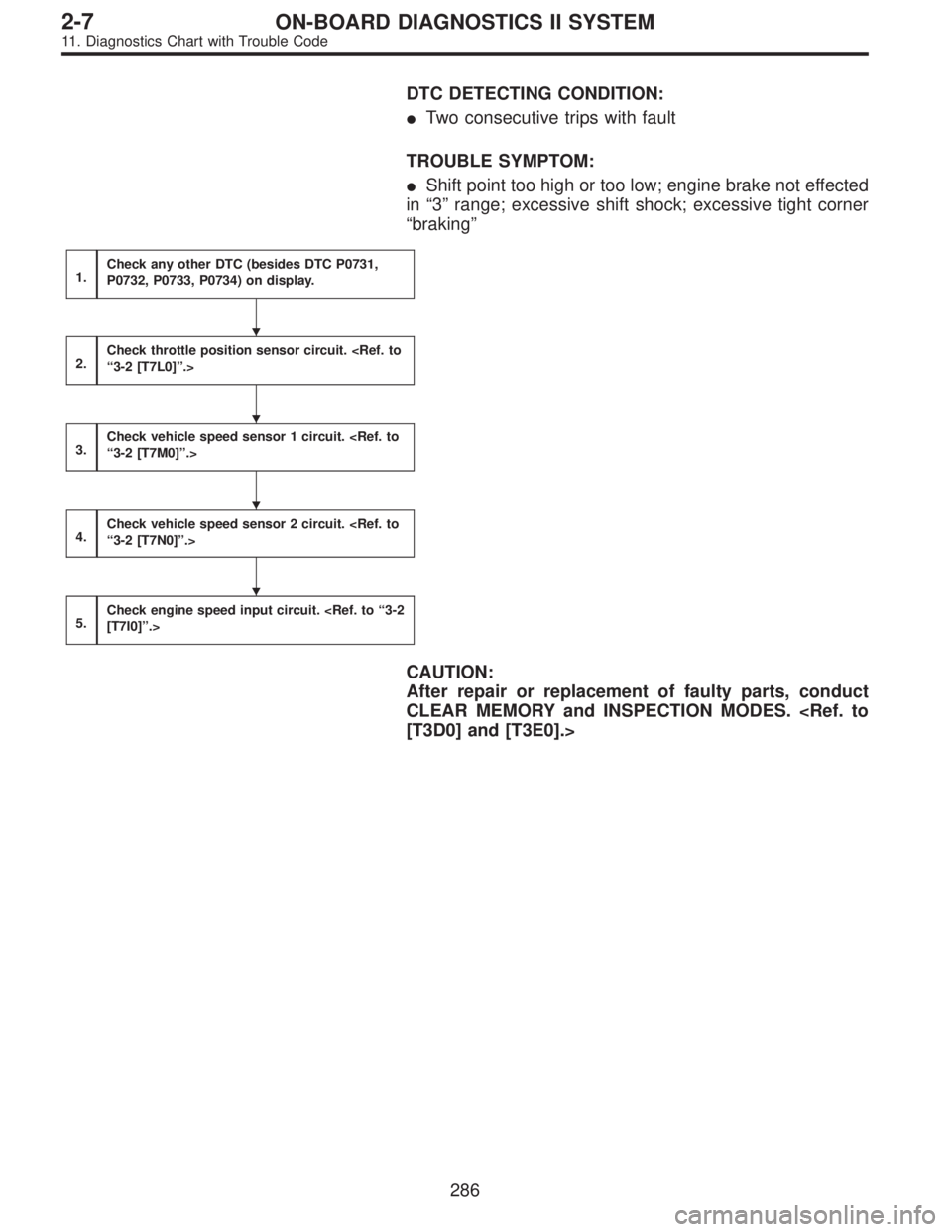
DTC DETECTING CONDITION:
�Two consecutive trips with fault
TROUBLE SYMPTOM:
�Shift point too high or too low; engine brake not effected
in“3”range; excessive shift shock; excessive tight corner
“braking”
1.Check any other DTC (besides DTC P0731,
P0732, P0733, P0734) on display.
2.Check throttle position sensor circuit.
“3-2 [T7L0]”.>
3.Check vehicle speed sensor 1 circuit.
“3-2 [T7M0]”.>
4.Check vehicle speed sensor 2 circuit.
“3-2 [T7N0]”.>
5.Check engine speed input circuit.
[T7I0]”.>
CAUTION:
After repair or replacement of faulty parts, conduct
CLEAR MEMORY and INSPECTION MODES.
[T3D0] and [T3E0].>
�
�
�
�
286
2-7ON-BOARD DIAGNOSTICS II SYSTEM
11. Diagnostics Chart with Trouble Code
Page 1494 of 2248
2CHECK THROTTLE POSITION SENSOR CIR-
CUIT.
: Is there any trouble in throttle position sen-
sor circuit?
: Repair or replace throttle position sensor circuit.
: Go to step 3.
3
CHECK VEHICLE SPEED SENSOR 1 CIRCUIT.
: Is there any trouble in vehicle speed sensor
1 circuit?
: Repair or replace vehicle speed sensor 1 circuit.
: Go to step 4.
4
CHECK VEHICLE SPEED SENSOR 2 CIRCUIT.
: Is there any trouble in vehicle speed sensor
2 circuit?
: Repair or replace vehicle speed sensor 2 circuit.
: Go to step 5.
5
CHECK ENGINE SPEED INPUT CIRCUIT.
: Is there any trouble in engine speed input
circuit?
: Repair or replace engine speed input circuit.
: Go to next.
: Is there poor contact in TCM connector?
: Repair poor contact in TCM connector.
: Go to next.
: Is there any mechanical trouble in automatic
transmission?
: Repair or replace automatic transmission.
: Replace TCM with a new one.
288
2-7ON-BOARD DIAGNOSTICS II SYSTEM
11. Diagnostics Chart with Trouble Code
Page 1496 of 2248
1.Check any other DTC (besides DTC P0740) on
display.
2.Check duty solenoid B circuit.
[T7B0]”.>
3.Check throttle position sensor circuit.
“3-2 [T7L0]”.>
4.Check vehicle speed sensor 1 circuit.
“3-2 [T7M0]”.>
5.Check vehicle speed sensor 2 circuit.
“3-2 [T7N0]”.>
6.Check engine speed input circuit.
[T7I0]”.>
7.Check inhibitor switch circuit.
DTC P0705 [T11AN0]”.>
8.Check brake light switch circuit.
DTC P0703 [T11AM0]”.>
9.Check ATF temperature sensor circuit.
“3-2 [T7G0]”.>
CAUTION:
After repair or replacement of faulty parts, conduct
CLEAR MEMORY and INSPECTION MODES.
[T3D0] and [T3E0].>
�
�
�
�
�
�
�
�
290
2-7ON-BOARD DIAGNOSTICS II SYSTEM
11. Diagnostics Chart with Trouble Code
Page 1498 of 2248
2
CHECK DUTY SOLENOID B CIRCUIT.
: Is there any trouble in duty solenoid B cir-
cuit?
: Repair or replace duty solenoid B circuit.
: Go to step 3.
3CHECK THROTTLE POSITION SENSOR CIR-
CUIT.
: Is there any trouble in throttle position sen-
sor circuit?
: Repair or replace throttle position sensor circuit.
: Go to step 4.
4
CHECK VEHICLE SPEED SENSOR 1 CIRCUIT.
: Is there any trouble in vehicle speed sensor
1 circuit?
: Repair or replace vehicle speed sensor 1 circuit.
: Go to step 5.
5
CHECK VEHICLE SPEED SENSOR 2 CIRCUIT.
: Is there any trouble in vehicle speed sensor
2 circuit?
: Repair or replace vehicle speed sensor 2 circuit.
: Go to step 6.
6
CHECK ENGINE SPEED INPUT CIRCUIT.
: Is there any trouble in engine speed input
circuit?
: Repair or replace engine speed input circuit.
: Go to step 7.
292
2-7ON-BOARD DIAGNOSTICS II SYSTEM
11. Diagnostics Chart with Trouble Code
Page 1537 of 2248
—
DESCRIPTION:
�The engine cooling system consists of a down-flow
radiator which features high heat-dissipation performanc")
OBD0527
BI: DTC P1500
—RADIATOR FAN RELAY 1 CIRCUIT
MALFUNCTION (FAN
—1)—
DESCRIPTION:
�The engine cooling system consists of a down-flow
radiator which features high heat-dissipation performance,
an electric motor fan, an engine coolant pump, a
thermostat, and an engine coolant temperature sensor.
�The ON-OFF control of the radiator fan is governed by
the ECM which receives signals sent from the engine cool-
ant temperature sensor. On models which are equipped
with an air conditioning system, the ECM receives signals
sent from the engine coolant temperature sensor, vehicle
speed sensor 2 and A/C switch. These signals simulta-
neously turn ON or OFF the radiator main fan and radiator
sub fan as well as setting them at“HI”or“LO”speed.
[Without A/C models]
Engine coolant temperature signal *1ECM output signal Operation of radiator fan
Radiator fan relay 1 Main
ON ON ON
OFF OFF OFF
*1 ON: Above 95°C (203°F), OFF: Below 89°C (192°F)
[With A/C models]
Engine coolant
temperature
signal *2A/C compressorVehicle speed
signal *3ECM output signal Operation of radiator fan
Radiator fan
relay 1Radiator fan
relay 2Main Sub
ONONON ON ON HI HI
OFF ON ON HI HI
OFFON ON ON HI HI
OFF ON OFF LO LO
OFFONON ON ON HI HI
OFF ON OFF LO LO
OFFON OFF OFF OFF OFF
OFF OFF OFF OFF OFF
*2 ON: Above 95°C (203°F), OFF: Below 89°C (192°F)
*3 ON: Above 20 km/h (12 MPH), OFF: Below 10 km/h (6 MPH)
331
2-7ON-BOARD DIAGNOSTICS II SYSTEM
11. Diagnostics Chart with Trouble Code
Page 1547 of 2248
OBD0501
BK: DTC P1700
—THROTTLE POSITION SENSOR CIRCUIT
MALFUNCTION FOR AUTOMATIC
TRANSMISSION (ATTH)—
DESCRIPTION:
�The throttle position sensor provides electrical signals
corresponding to the throttle opening. The throttle opening
and accelerator depression speed are detected by this
throttle position sensor output.
�Detects throttle opening and determines shift point, line
pressure and lockup vehicle speed according to engine
load.
SOR CIRCUIT MALFUNCTION—[T11G0]”.>
DTC DETECTING CONDITION:
�Two consecutive trips with fault
TROUBLE SYMPTOM:
�Shift point too high or too low; engine brake not effected
in“3”range; excessive shift shock; excessive tight corner
“braking”
341
2-7ON-BOARD DIAGNOSTICS II SYSTEM
11. Diagnostics Chart with Trouble Code
Page 1557 of 2248
 Check that selector lever does not move from“N”to“R”
without pushing the bu")
G3M0717
3. OPERATION OF SHIFT SELECTOR LEVER
WARNING:
Stop the engine while checking operation of selector
lever.
1) Check that selector lever does not move from“N”to“R”
without pushing the button.
2) Check that selector lever does not move from“R”to“P”
without pushing the button.
3) Check that selector lever does not move from“P”to“R”
without pushing the button.
4) Check that selector lever does not move from“3”to“2”
without pushing the button.
3. Electrical Components Location
1. SENSOR AND CONTROL MODULE
B3M0178B
�1Throttle position sensor
�
2Dropping resistor
�
3Vehicle speed sensor 2
�
4Inhibitor switch
�
5ECM
�
6Vehicle speed sensor 1 (AWD)
�
7Vehicle speed sensor 1 (FWD)
�
8TCM�
9Data link connector (for Subaru select monitor only)
�
10Data link connector (for Subaru select monitor and OBD-II
general scan tool)
�
11Diagnosis connector
�
12Diagnosis terminal
�
13AT OIL TEMP indicator light
(AT diagnostic indicator light)
3
3-2AUTOMATIC TRANSMISSION AND DIFFERENTIAL
2. Pre-inspection - 3. Electrical Components Location
Page 1558 of 2248
 Check that selector lever does not move from“N”to“R”
without pushing the bu")
G3M0717
3. OPERATION OF SHIFT SELECTOR LEVER
WARNING:
Stop the engine while checking operation of selector
lever.
1) Check that selector lever does not move from“N”to“R”
without pushing the button.
2) Check that selector lever does not move from“R”to“P”
without pushing the button.
3) Check that selector lever does not move from“P”to“R”
without pushing the button.
4) Check that selector lever does not move from“3”to“2”
without pushing the button.
3. Electrical Components Location
1. SENSOR AND CONTROL MODULE
B3M0178B
�1Throttle position sensor
�
2Dropping resistor
�
3Vehicle speed sensor 2
�
4Inhibitor switch
�
5ECM
�
6Vehicle speed sensor 1 (AWD)
�
7Vehicle speed sensor 1 (FWD)
�
8TCM�
9Data link connector (for Subaru select monitor only)
�
10Data link connector (for Subaru select monitor and OBD-II
general scan tool)
�
11Diagnosis connector
�
12Diagnosis terminal
�
13AT OIL TEMP indicator light
(AT diagnostic indicator light)
3
3-2AUTOMATIC TRANSMISSION AND DIFFERENTIAL
2. Pre-inspection - 3. Electrical Components Location

![SUBARU LEGACY 1995 Service Repair Manual 1.Check any other DTC (besides DTC P0740) on
display.
2.Check duty solenoid B circuit. <Ref. to“3-2
[T7B0]”.>
3.Check throttle position sensor circuit. <Ref. to
“3-2 [T7L0]”.>
4.Check vehicle](/manual-img/17/57432/w960_57432-1495.png "SUBARU LEGACY 1995 Service Repair Manual 1.Check any other DTC (besides DTC P0740) on
display.
2.Check duty solenoid B circuit. <Ref. to“3-2
[T7B0]”.>
3.Check throttle position sensor circuit. <Ref. to
“3-2 [T7L0]”.>
4.Check vehicle")