Page 1771 of 2248

—
�Compare speedometer with monitor indications.
�F04: RL wheel speed is indicated in mile per hour (mile/
h).
�F08: RL wheel speed i")
B4M0483
F: MODE F04 AND F08
—REAR LEFT WHEEL SPEED SIGNAL (RL)
—
�Compare speedometer with monitor indications.
�F04: RL wheel speed is indicated in mile per hour (mile/
h).
�F08: RL wheel speed is indicated in kilometer per hour
(km/h).
NOTE:
The monitor as shown, indicates that RL wheel speed is 50
mile/h.
B4M0484
G: MODE F09
—PEDAL STROKE SENSOR SIGNAL (PSS)
—
�Indicates the output step number of the pedal stroke
sensor.
LED No. Signal name Display
1 TCS OFF switch OF
2 Stop light switch B1
3 Valve relay signal VR
4 Valve relay monitor VM
5 Motor relay signal MR
6 Motor sensor MS
7 Brake fluid level sensor FS
8——
9——
10——
OF B1 VR VM MR
MS FS———
1
2345
678910
H: MODE FA0
—ON↔OFF SIGNAL—
Requirement for LED“ON”
LED No. 1 T.C.S OFF switch is turned ON.
LED No. 2 Stop light switch is turned ON. (With brake
pedal depressed.)
LED No. 3 Valve relay is turned OFF.
LED No. 4 Valve relay is turned OFF.
LED No. 5 Motor relay is turned ON.
LED No. 6 Motor is rotating.
LED No. 7 Brake fluid level sensor is turned ON. (Brake
fluid is insufficient.)
90
4-4bBRAKES
9. Select Monitor Function Mode
Page 1775 of 2248
CodeDisplay screen
(FB0)Diagnostic items (select monitor FB1) Display screen (FB1)Ref. to
4-4b
Normal 11 NO TROUBLE Normal NO TROUBLE [T10C")
B: LIST OF TROUBLE CODE
Diagnostic items
(select monitor FB0)CodeDisplay screen
(FB0)Diagnostic items (select monitor FB1) Display screen (FB1)Ref. to
4-4b
Normal 11 NO TROUBLE Normal NO TROUBLE [T10C0]
Detection of FR sensor
hardware21 FR.SS HARDOpen circuit of FR sensor FR.SS OPEN [T10D1]
Short circuit of FR sensor FR.SS SHORT [T10D2]
Detection of FR sensor
software22 FR.SS SOFTFR sensor, variations in wheel speed FR.SS W.SPEED [T10E1]
FR sensor, reduced pressure mode FR.SS OR MV [T10E2]
FR sensor, wheel speed higher than prescribed FR.SS OVER [T10E3]
Detection of FL sensor
hardware23 FL.SS HARDOpen circuit of FL sensor FL.SS OPEN [T10F1]
Short circuit of FL sensor FL.SS SHORT [T10F2]
Detection of FL sensor
software24 FL.SS SOFTFL sensor, variations in wheel speed FL.SS W.SPEED [T10G1]
FL sensor, reduced pressure mode FL.SS OR MV [T10G2]
FL sensor, wheel speed higher than prescribed FL.SS OVER [T10G3]
Detection of RR sensor
hardware25 RR.SS HARDOpen circuit of RR sensor RR.SS OPEN [T10H1]
Short circuit of RR sensor RR.SS SHORT [T10H2]
Detection of RR sensor
software26 RR.SS SOFTRR sensor, variations in wheel speed RR.SS W.SPEED [T10I1]
RR sensor, reduced pressure mode RR.SS OR MV [T10I2]
RR sensor, wheel speed higher than prescribed RR.SS OVER [T10I3]
Detection of RL sensor
hardware27 RL.SS HARDOpen circuit of RL sensor RL.SS OPEN [T10J1]
Short circuit of RL sensor RL.SS SHORT [T10J2]
Detection of RL sensor
software28 RL.SS SOFTRL sensor, variations in wheel speed RL.SS W.SPEED [T10K1]
RL sensor, reduced pressure mode RL.SS OR MV [T10K2]
RL sensor, wheel speed higher than prescribed RL.SS OVER [T10K3]
Abnormal FR.IN valve 31 FR.IN VALVE Abnormal FR.IN valve FR.IN VALVE [T10L0]
Abnormal FR.OUT
valve32 FR.OUT VALVE Abnormal FR.OUT valve FR.OUT VALVE [T10M0]
Abnormal FL.IN valve 33 FL.IN VALVE Abnormal FL.IN valve FL.IN VALVE [T10N0]
Abnormal FL.OUT
valve34 FL.OUT VALVE Abnormal FL.OUT valve FL.OUT VALVE [T10O0]
Abnormal RR.IN valve 35 RR.IN VALVE Abnormal RR.IN valve RR.IN VALVE [T10P0]
Abnormal RR.OUT
valve36 RR.OUT VALVE Abnormal RR.OUT valve RR.OUT VALVE [T10Q0]
Abnormal RL.IN valve 37 RL.IN VALVE Abnormal RL.IN valve RL.IN VALVE [T10R0]
Abnormal RL.OUT
valve38 RL.OUT VALVE Abnormal RL.OUT valve RL.OUT VALVE [T10S0]
Abnormal ECM 41 ECU Abnormal ECM ECU [T10T0]
Abnormal line voltage 42 HIGH VOLTAGE Abnormal line voltage HIGH VOLTAGE [T10U0]
Abnormal EGI commu-
nication line43 EGI LINE Abnormal EGI communication line EGI LINE [T10V0]
Abnormal valve relay 51 V.RELAYValve relay ON failure V.RELAY ON [T10W1]
Valve relay OFF failure V.RELAY OFF [T10W2]
Abnormal motor sys-
tem52 MOTORMotor relay ON failure MOTOR ON [T10X1]
Motor relay OFF failure MOTOR OFF [T10X2]
94
4-4bBRAKES
10. Diagnostic Chart with Select Monitor
Page 1776 of 2248
CodeDisplay screen
(FB0)Diagnostic items (select monitor FB1) Display screen (FB1)Ref. to
4-4b
Abnormal stroke sen-
sor and stop light
switch54 PSS & BLSOpen/short")
Diagnostic items
(select monitor FB0)CodeDisplay screen
(FB0)Diagnostic items (select monitor FB1) Display screen (FB1)Ref. to
4-4b
Abnormal stroke sen-
sor and stop light
switch54 PSS & BLSOpen/short circuits of stroke sensor B.SW HARD [T10Y1]
Comparison of stroke sensor and acceleration B.SW SOFT(G) [T10Y2]
Comparison of stroke sensor and stop light switch B.SW SOFT(B) [T10Y3]
Comparison of stroke sensor and pump B.SW SOFT(P) [T10Y4]
Open circuit of stop light switch B.SW SOFT(O) [T10Y5]
Abnormal fluid level
sensor line57 FLUID LEVEL SS Abnormal fluid level sensor line FLUID LEVEL SS [T10Z0]
Abnormal pressure
switch58 PRESSURE SW Abnormal pressure switch PRESSURE SW [T10AA0]
Abnormal TCS1 valve 61 TCS1 VALVE Abnormal TCS1 valve TCS1 VALVE [T10AB0]
Abnormal TCS2 valve 62 TCS2 VALVE Abnormal TCS2 valve TCS2 VALVE [T10AC0]
1. IF THE SELECT MONITOR IS USED FOR
TROUBLESHOOTING, IT IS ADVISED TO FOLLOW
THE PROCEDURE BELOW
1) Activate function FB0 to read the most recent trouble
code and record it.
2) Activate function FB1 to read all trouble codes and
record them.
(If troubles occur in the wheel speed sensor, stop & brake
switch, valve relay or motor system, detailed data on
troubles are displayed by the FB1 function, allowing you to
easily locate points where need repair.)
3) Perform troubleshooting mainly in the FB1 mode.
95
4-4bBRAKES
10. Diagnostic Chart with Select Monitor
Page 1779 of 2248
B4M0493
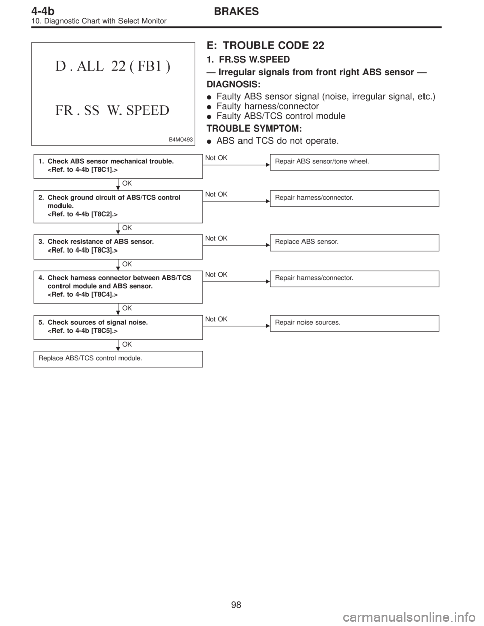
E: TROUBLE CODE 22
1. FR.SS W.SPEED
—Irregular signals from front right ABS sensor—
DIAGNOSIS:
�Faulty ABS sensor signal (noise, irregular signal, etc.)
�Faulty harness/connector
�Faulty ABS/TCS control module
TROUBLE SYMPTOM:
�ABS and TCS do not operate.
1. Check ABS sensor mechanical trouble.
OK
�Not OK
Repair ABS sensor/tone wheel.
2. Check ground circuit of ABS/TCS control
module.
OK
�Not OK
Repair harness/connector.
3. Check resistance of ABS sensor.
OK
�Not OK
Replace ABS sensor.
4. Check harness connector between ABS/TCS
control module and ABS sensor.
OK
�Not OK
Repair harness/connector.
5. Check sources of signal noise.
OK
�Not OK
Repair noise sources.
Replace ABS/TCS control module.
�
�
�
�
�
98
4-4bBRAKES
10. Diagnostic Chart with Select Monitor
Page 1781 of 2248
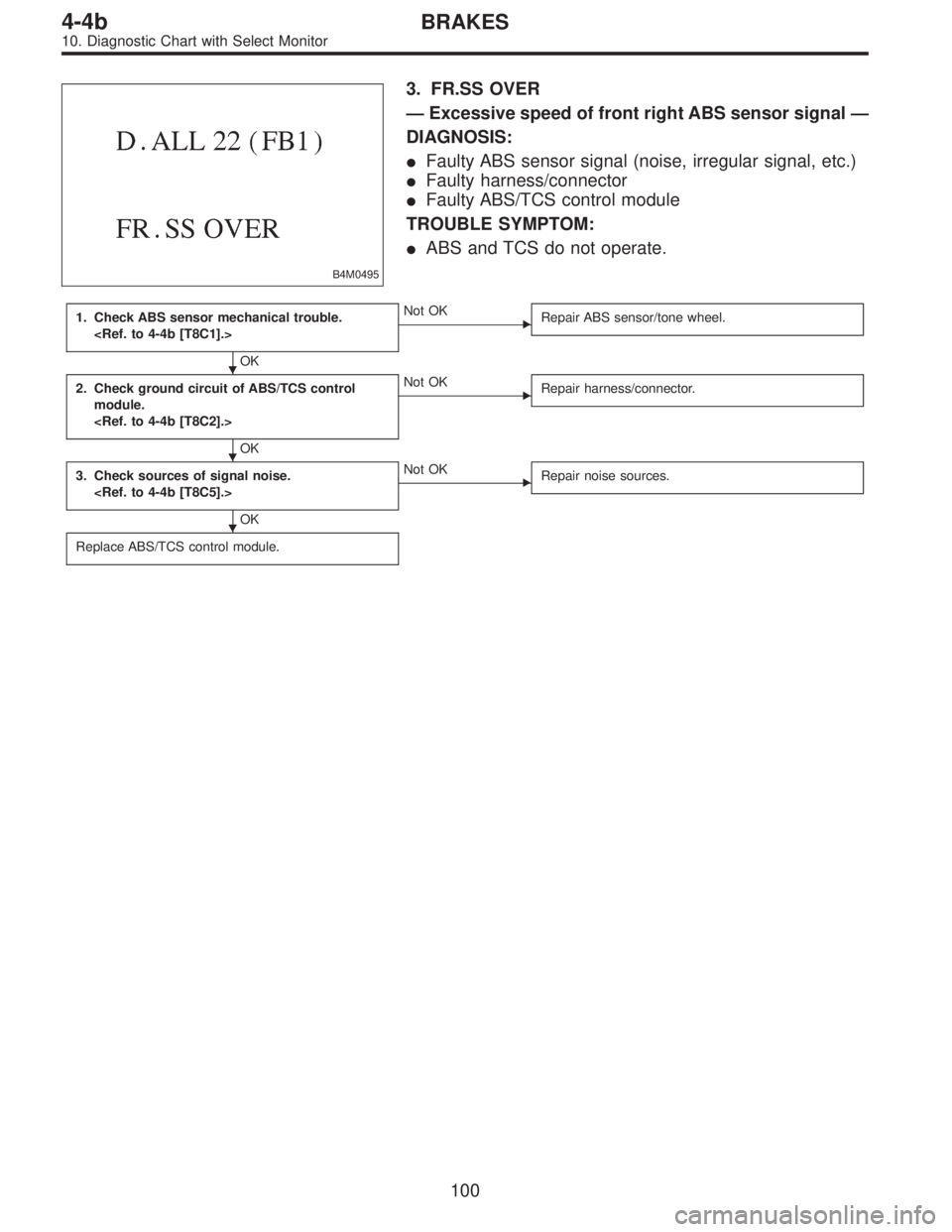
B4M0495
3. FR.SS OVER
—Excessive speed of front right ABS sensor signal—
DIAGNOSIS:
�Faulty ABS sensor signal (noise, irregular signal, etc.)
�Faulty harness/connector
�Faulty ABS/TCS control module
TROUBLE SYMPTOM:
�ABS and TCS do not operate.
1. Check ABS sensor mechanical trouble.
OK
�Not OK
Repair ABS sensor/tone wheel.
2. Check ground circuit of ABS/TCS control
module.
OK
�Not OK
Repair harness/connector.
3. Check sources of signal noise.
OK
�Not OK
Repair noise sources.
Replace ABS/TCS control module.
�
�
�
100
4-4bBRAKES
10. Diagnostic Chart with Select Monitor
Page 1783 of 2248

�Faulty harness/connector
�Faulty AB")
B4M0498
G: TROUBLE CODE 24
1. FL.SS W.SPEED
—Irregular signals from front left ABS sensor—
DIAGNOSIS:
�Faulty ABS sensor signal (noise, irregular signal, etc.)
�Faulty harness/connector
�Faulty ABS/TCS control module
TROUBLE SYMPTOM:
�ABS and TCS do not operate.
NOTE:
The procedures used are the same as those for FR.SS
W.SPEED.
B4M0499
2. FL.SS OR MV
—Irregular signals from front left ABS sensor in
decompressing mode—
DIAGNOSIS:
�Faulty ABS sensor signal (noise, irregular signal, etc.)
�Faulty hydraulic unit
�Faulty harness/connector
�Faulty ABS/TCS control module
TROUBLE SYMPTOM:
�ABS and TCS do not operate.
NOTE:
The procedures used are the same as those for FR.SS OR
MV.
B4M0500
3. FL.SS OVER
—Excessive speed of front left ABS sensor signal—
DIAGNOSIS:
�Faulty ABS sensor signal (noise, irregular signal, etc.)
�Faulty harness/connector
�Faulty ABS/TCS control module
TROUBLE SYMPTOM:
�ABS and TCS do not operate.
NOTE:
The procedures used are the same as those for FR.SS
OVER.
102
4-4bBRAKES
10. Diagnostic Chart with Select Monitor
Page 1785 of 2248

�Faulty harness/connector
�Faulty AB")
B4M0503
I: TROUBLE CODE 26
1. RR.SS W.SPEED
—Irregular signals from rear right ABS sensor—
DIAGNOSIS:
�Faulty ABS sensor signal (noise, irregular signal, etc.)
�Faulty harness/connector
�Faulty ABS/TCS control module
TROUBLE SYMPTOM:
�ABS and TCS do not operate.
NOTE:
The procedures used are the same as those for FR.SS
W.SPEED.
B4M0504
2. RR.SS OR MV
—Irregular signals from rear right ABS sensor in
decompressing mode—
DIAGNOSIS:
�Faulty ABS sensor signal (noise, irregular signal, etc.)
�Faulty hydraulic unit
�Faulty harness/connector
�Faulty ABS/TCS control module
TROUBLE SYMPTOM:
�ABS and TCS do not operate.
NOTE:
The procedures used are the same as those for FR.SS OR
MV.
B4M0505
3. RR.SS OVER
—Excessive speed of rear right ABS sensor signal—
DIAGNOSIS:
�Faulty ABS sensor signal (noise, irregular signal, etc.)
�Faulty harness/connector
�Faulty ABS/TCS control module
TROUBLE SYMPTOM:
�ABS and TCS do not operate.
NOTE:
The procedures used are the same as those for FR.SS
OVER.
104
4-4bBRAKES
10. Diagnostic Chart with Select Monitor
Page 1787 of 2248

�Faulty harness/connector
�Faulty ABS")
B4M0508
K: TROUBLE CODE 28
1. RL.SS W.SPEED
—Irregular signals from rear left ABS sensor—
DIAGNOSIS:
�Faulty ABS sensor signal (noise, irregular signal, etc.)
�Faulty harness/connector
�Faulty ABS/TCS control module
TROUBLE SYMPTOM:
�ABS and TCS do not operate.
NOTE:
The procedures used are the same as those for FR.SS
W.SPEED.
B4M0509
2. RL.SS OR MV
—Irregular signals from rear left ABS sensor in
decompressing mode—
DIAGNOSIS:
�Faulty ABS sensor signal (noise, irregular signal, etc.)
�Faulty hydraulic unit
�Faulty harness/connector
�Faulty ABS/TCS control module
TROUBLE SYMPTOM:
�ABS and TCS do not operate.
NOTE:
The procedures used are the same as those for FR.SS OR
MV.
B4M0510
3. RL.SS OVER
—Excessive speed of rear left ABS sensor signal—
DIAGNOSIS:
�Faulty ABS sensor signal (noise, irregular signal, etc.)
�Faulty harness/connector
�Faulty ABS/TCS control module
TROUBLE SYMPTOM:
�ABS and TCS do not operate.
NOTE:
The procedures used are the same as those for FR.SS
OVER.
106
4-4bBRAKES
10. Diagnostic Chart with Select Monitor