Page 15 of 2248
 Before checking idle speed, check the following:
(1) Ensure that air cleaner element is free from
clogging, ignition timing is correct, spark plugs are in
good c")
3. Engine Idle Speed
A: MEASUREMENT
1) Before checking idle speed, check the following:
(1) Ensure that air cleaner element is free from
clogging, ignition timing is correct, spark plugs are in
good condition, and that hoses are connected properly.
(2) Ensure that malfunction indicator light (CHECK
ENGINE light) does not illuminate.
2) Warm-up the engine.
G2M0096
3) Connect Subaru Select Monitor or the OBD-II general
scan tool to data link connector.
CAUTION:
When connecting Subaru Select Monitor, turn ignition
switch to OFF.
4) Start the engine and measure engine speed.
NOTE:
Engine speed is indicated on Subaru Select Monitor by
selecting “MODE F04”.
G2M0097
NOTE:
�When using the OBD-II general scan tool, carefully read
its operation manual.
�When Subaru Select Monitor is not used, attach the
pickup sensor on tachometer (Secondary pickup type) to
#1 cylinder spark plug cord.
�This ignition system provides simultaneous ignition for
#1 and #2 plugs. It must be noted that some tachometers
may register twice that of actual engine speed.
3
2-2
3. Engine Idle Speed
Page 261 of 2248
G2M0266
1) Open front hood fully, and support with stay.
2) Disconnect battery ground terminal.
3) Remove air intake duct.
G2M0544
4) Disconnect connectors and cables.
(1) Disconnect the following connectors.
�Front oxygen sensor connector
G2M0307
�Transmission harness connector
�Transmission ground terminal
B2M0337
�Neutral position switch connector (MT model)
�Back-up light switch connector (MT model)
G2M0827
�Vehicle speed sensor 2
27
2-11SERVICE PROCEDURE
3. Transmission
Page 275 of 2248
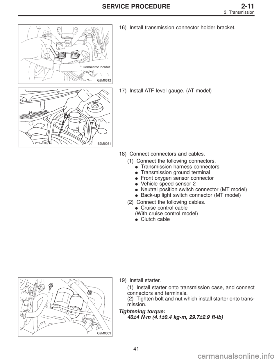
G2M0312
16) Install transmission connector holder bracket.
B2M0031
17) Install ATF level gauge. (AT model)
18) Connect connectors and cables.
(1) Connect the following connectors.
�Transmission harness connectors
�Transmission ground terminal
�Front oxygen sensor connector
�Vehicle speed sensor 2
�Neutral position switch connector (MT model)
�Back-up light switch connector (MT model)
(2) Connect the following cables.
�Cruise control cable
(With cruise control model)
�Clutch cable
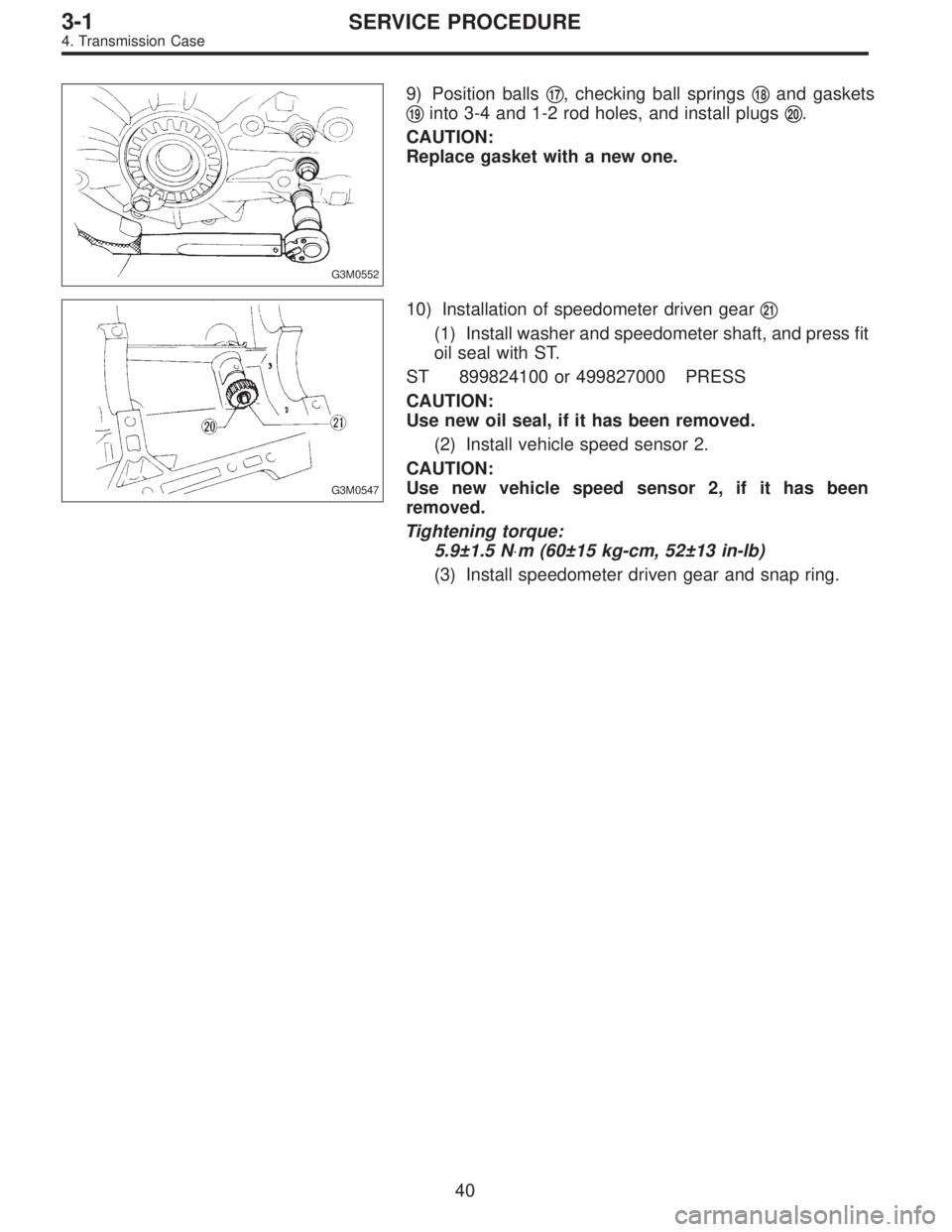
G2M0309
19) Install starter.
(1) Install starter onto transmission case, and connect
connectors and terminals.
(2) Tighten bolt and nut which install starter onto trans-
mission.
Tightening torque:
40±4 N⋅m (4.1±0.4 kg-m, 29.7±2.9 ft-lb)
41
2-11SERVICE PROCEDURE
3. Transmission
Page 311 of 2248
 Drive out spring pin�6, and pull out 3-4 fork rod�7and
shifter fork�
8.
NOTE:
When removing rod, keep other rods in neutral. Also, when
pulling out straight pin, remove it toward inside of")
B3M0333B
3) Drive out spring pin�6, and pull out 3-4 fork rod�7and
shifter fork�
8.
NOTE:
When removing rod, keep other rods in neutral. Also, when
pulling out straight pin, remove it toward inside of case so
that it may not hit against case.
4) Drive out straight pin�
9, and pull out 1-2 fork rod�10and
shifter fork�
11.
G3M0602
5) Pull out straight pin�12, and remove idler gear shaft�13,
reverse idler gear�
14and washer�15.
6) Remove outer snap ring�
16, and pull out reverse shifter
rod arm�
17from reverse fork rod�18. Then take out ball,
spring and interlock plunger from rod.
And then remove rod.
NOTE:
When pulling out reverse shifter rod arm, be careful not to
let ball pop out of arm.
7) Remove reverse shifter lever�
19.
G3M0546
8) Remove differential side retainers using ST.
ST 499787000 WRENCH ASSY
G3M0547
9) Remove outer snap ring�20and pull out speedometer
driven gear�
21. Next, remove vehicle speed sensor 2, oil
seal, speedometer shaft�
22and washer.
36
3-1SERVICE PROCEDURE
4. Transmission Case
Page 315 of 2248
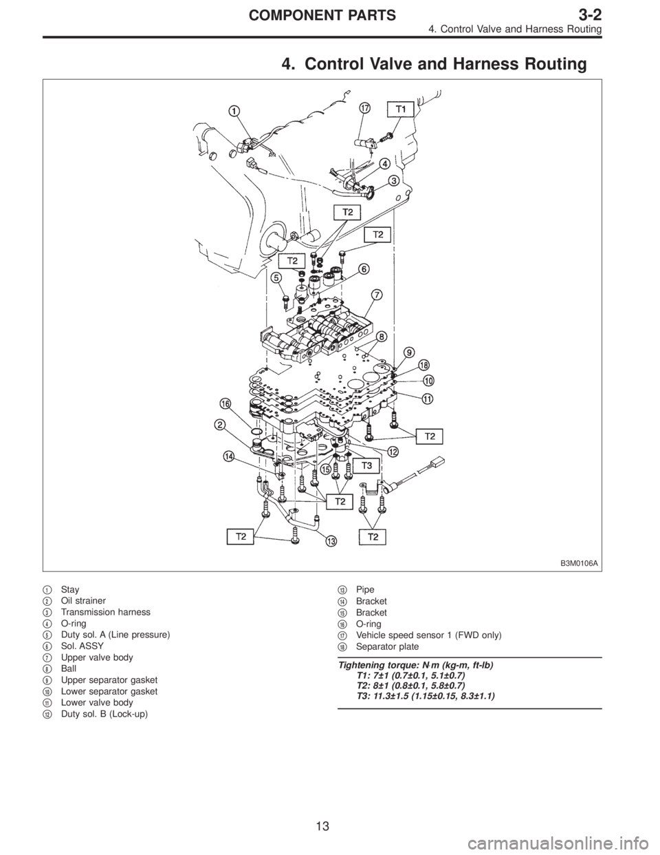
G3M0552
9) Position balls�17, checking ball springs�18and gaskets
�
19into 3-4 and 1-2 rod holes, and install plugs�20.
CAUTION:
Replace gasket with a new one.
G3M0547
10) Installation of speedometer driven gear�21
(1) Install washer and speedometer shaft, and press fit
oil seal with ST.
ST 899824100 or 499827000 PRESS
CAUTION:
Use new oil seal, if it has been removed.
(2) Install vehicle speed sensor 2.
CAUTION:
Use new vehicle speed sensor 2, if it has been
removed.
Tightening torque:
5.9±1.5 N⋅m (60±15 kg-cm, 52±13 in-lb)
(3) Install speedometer driven gear and snap ring.
40
3-1SERVICE PROCEDURE
4. Transmission Case
Page 357 of 2248
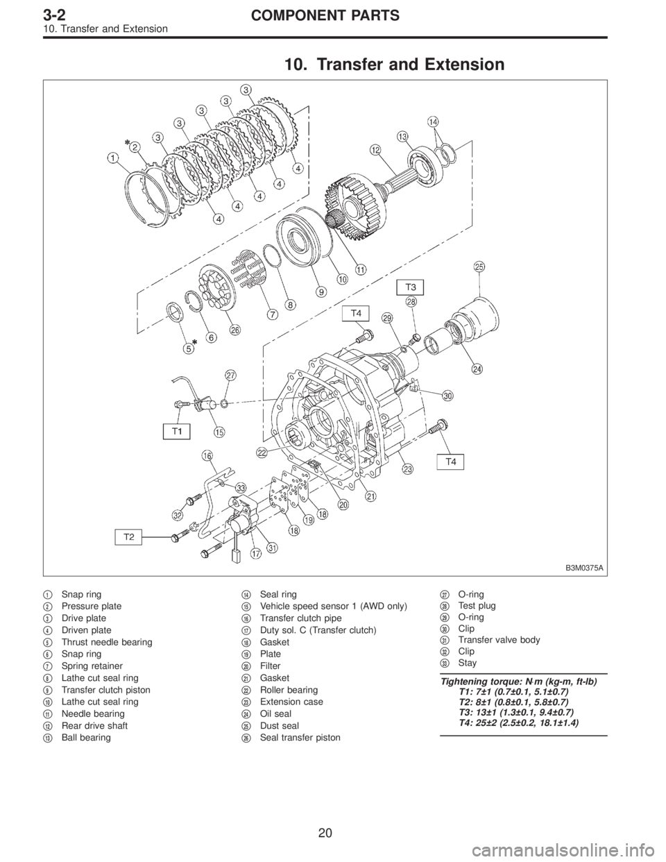
4. Control Valve and Harness Routing
B3M0106A
�1Stay
�
2Oil strainer
�
3Transmission harness
�
4O-ring
�
5Duty sol. A (Line pressure)
�
6Sol. ASSY
�
7Upper valve body
�
8Ball
�
9Upper separator gasket
�
10Lower separator gasket
�
11Lower valve body
�
12Duty sol. B (Lock-up)�
13Pipe
�
14Bracket
�
15Bracket
�
16O-ring
�
17Vehicle speed sensor 1 (FWD only)
�
18Separator plate
Tightening torque: N⋅m (kg-m, ft-lb)
T1: 7±1 (0.7±0.1, 5.1±0.7)
T2: 8±1 (0.8±0.1, 5.8±0.7)
T3: 11.3±1.5 (1.15±0.15, 8.3±1.1)
13
3-2COMPONENT PARTS
4. Control Valve and Harness Routing
Page 364 of 2248
10. Transfer and Extension
B3M0375A
�1Snap ring
�
2Pressure plate
�
3Drive plate
�
4Driven plate
�
5Thrust needle bearing
�
6Snap ring
�
7Spring retainer
�
8Lathe cut seal ring
�
9Transfer clutch piston
�
10Lathe cut seal ring
�
11Needle bearing
�
12Rear drive shaft
�
13Ball bearing�
14Seal ring
�
15Vehicle speed sensor 1 (AWD only)
�
16Transfer clutch pipe
�
17Duty sol. C (Transfer clutch)
�
18Gasket
�
19Plate
�
20Filter
�
21Gasket
�
22Roller bearing
�
23Extension case
�
24Oil seal
�
25Dust seal
�
26Seal transfer piston�
27O-ring
�
28Test plug
�
29O-ring
�
30Clip
�
31Transfer valve body
�
32Clip
�
33Stay
Tightening torque: N⋅m (kg-m, ft-lb)
T1: 7±1 (0.7±0.1, 5.1±0.7)
T2: 8±1 (0.8±0.1, 5.8±0.7)
T3: 13±1 (1.3±0.1, 9.4±0.7)
T4: 25±2 (2.5±0.2, 18.1±1.4)
20
3-2COMPONENT PARTS
10. Transfer and Extension
Page 369 of 2248
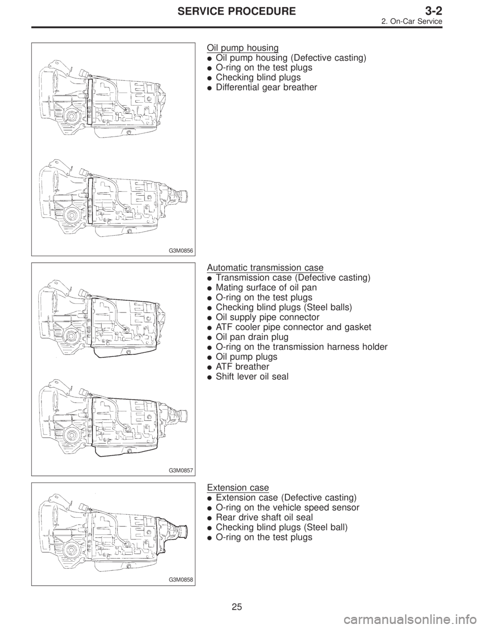
G3M0856
Oil pump housing
�Oil pump housing (Defective casting)
�O-ring on the test plugs
�Checking blind plugs
�Differential gear breather
G3M0857
Automatic transmission case
�Transmission case (Defective casting)
�Mating surface of oil pan
�O-ring on the test plugs
�Checking blind plugs (Steel balls)
�Oil supply pipe connector
�ATF cooler pipe connector and gasket
�Oil pan drain plug
�O-ring on the transmission harness holder
�Oil pump plugs
�ATF breather
�Shift lever oil seal
G3M0858
Extension case
�Extension case (Defective casting)
�O-ring on the vehicle speed sensor
�Rear drive shaft oil seal
�Checking blind plugs (Steel ball)
�O-ring on the test plugs
25
3-2SERVICE PROCEDURE
2. On-Car Service
 Open front hood fully, and support with stay.
2) Disconnect battery ground terminal.
3) Remove air intake duct.
G2M0544
4) Disconnect connectors and cables.
(1) Disconnect the following con")