Page 374 of 2248
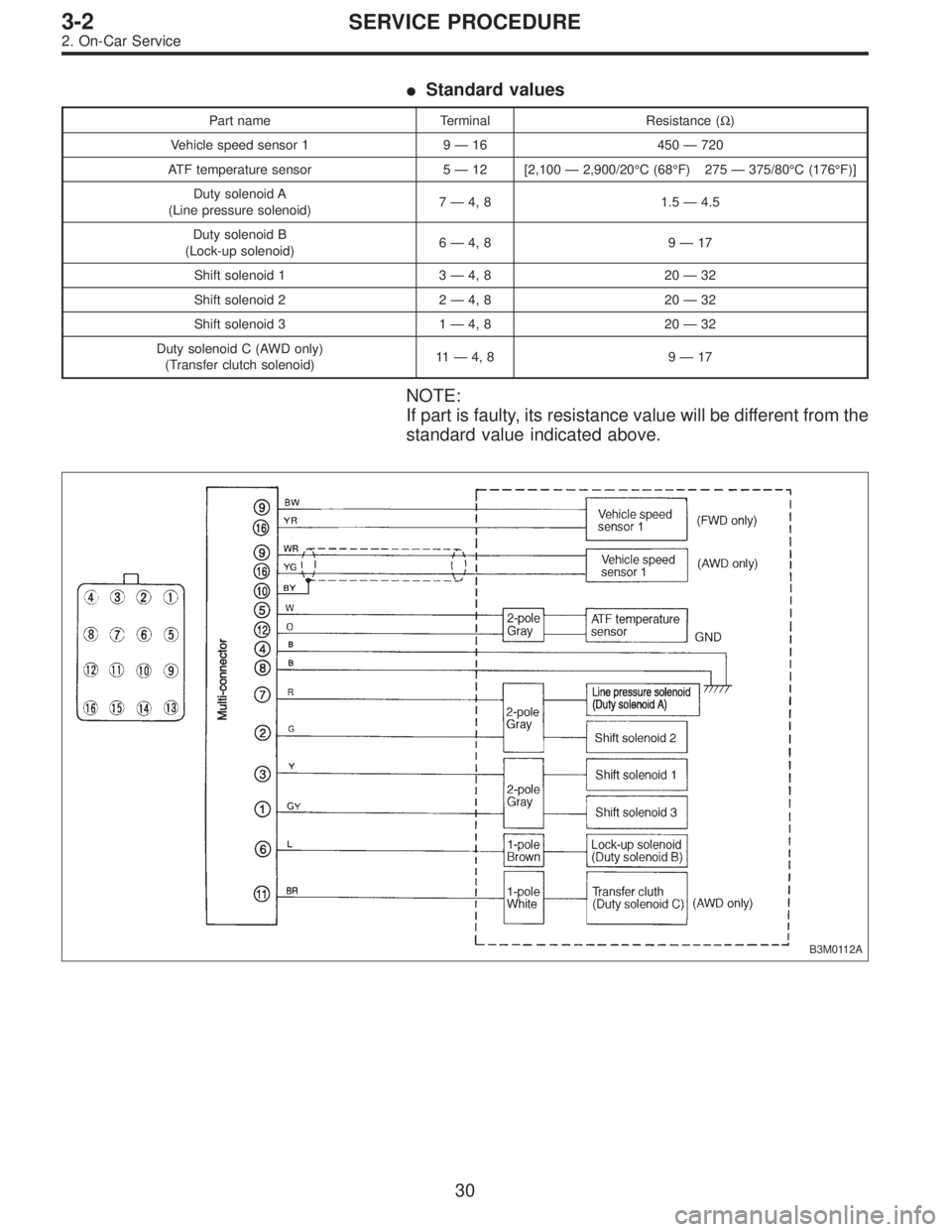
�Standard values
Part name Terminal Resistance (Ω)
Vehicle speed sensor 1 9—16 450—720
ATF temperature sensor 5—12 [2,100—2,900/20°C (68°F) 275—375/80°C (176°F)]
Duty solenoid A
(Line pressure solenoid)7—4, 8 1.5—4.5
Duty solenoid B
(Lock-up solenoid)6—4, 8 9—17
Shift solenoid 1 3—4, 8 20—32
Shift solenoid 2 2—4, 8 20—32
Shift solenoid 3 1—4, 8 20—32
Duty solenoid C (AWD only)
(Transfer clutch solenoid)11—4, 8 9—17
NOTE:
If part is faulty, its resistance value will be different from the
standard value indicated above.
B3M0112A
30
3-2SERVICE PROCEDURE
2. On-Car Service
Page 379 of 2248
G3M0307
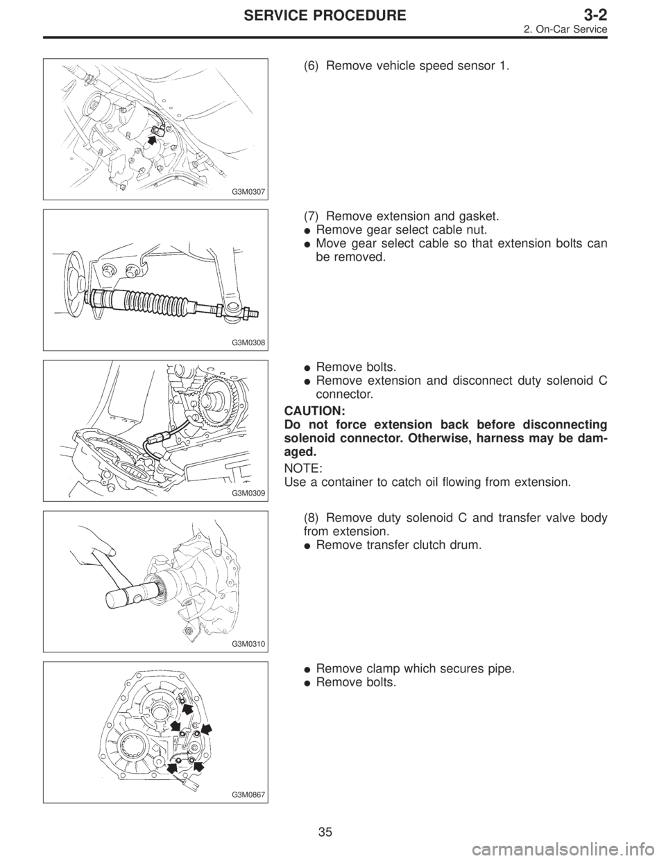
(6) Remove vehicle speed sensor 1.
G3M0308
(7) Remove extension and gasket.
�Remove gear select cable nut.
�Move gear select cable so that extension bolts can
be removed.
G3M0309
�Remove bolts.
�Remove extension and disconnect duty solenoid C
connector.
CAUTION:
Do not force extension back before disconnecting
solenoid connector. Otherwise, harness may be dam-
aged.
NOTE:
Use a container to catch oil flowing from extension.
G3M0310
(8) Remove duty solenoid C and transfer valve body
from extension.
�Remove transfer clutch drum.
G3M0867
�Remove clamp which secures pipe.
�Remove bolts.
35
3-2SERVICE PROCEDURE
2. On-Car Service
Page 380 of 2248
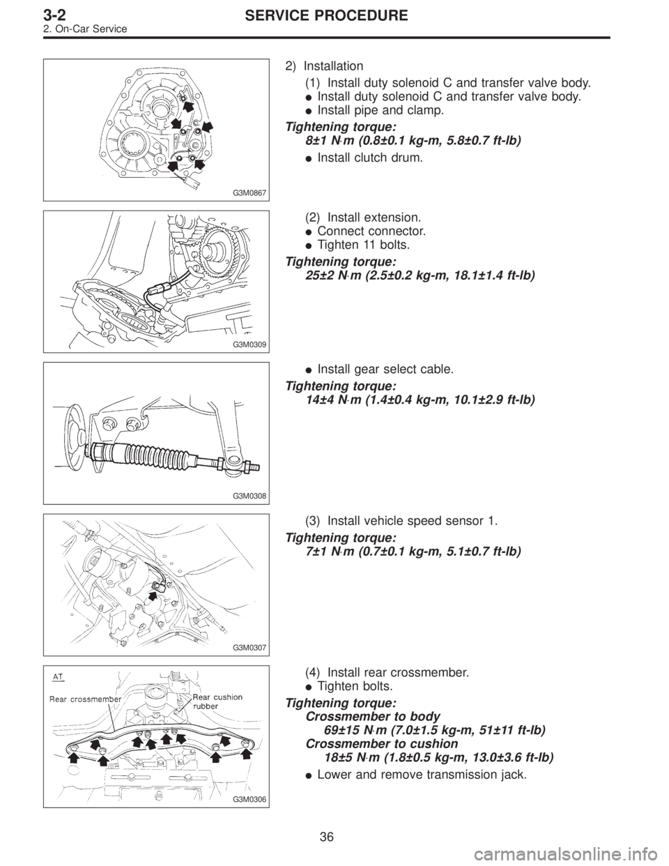
G3M0867
2) Installation
(1) Install duty solenoid C and transfer valve body.
�Install duty solenoid C and transfer valve body.
�Install pipe and clamp.
Tightening torque:
8±1 N⋅m (0.8±0.1 kg-m, 5.8±0.7 ft-lb)
�Install clutch drum.
G3M0309
(2) Install extension.
�Connect connector.
�Tighten 11 bolts.
Tightening torque:
25±2 N⋅m (2.5±0.2 kg-m, 18.1±1.4 ft-lb)
G3M0308
�Install gear select cable.
Tightening torque:
14±4 N⋅m (1.4±0.4 kg-m, 10.1±2.9 ft-lb)
G3M0307
(3) Install vehicle speed sensor 1.
Tightening torque:
7±1 N⋅m (0.7±0.1 kg-m, 5.1±0.7 ft-lb)
G3M0306
(4) Install rear crossmember.
�Tighten bolts.
Tightening torque:
Crossmember to body
69±15 N⋅m (7.0±1.5 kg-m, 51±11 ft-lb)
Crossmember to cushion
18±5 N⋅m (1.8±0.5 kg-m, 13.0±3.6 ft-lb)
�Lower and remove transmission jack.
36
3-2SERVICE PROCEDURE
2. On-Car Service
Page 394 of 2248
G3M0874
2. SEPARATION OF EACH SECTION
1) Separation of torque converter clutch case and trans-
mission case sections
CAUTION:
�Be careful not to damage the oil seal and bushing
inside the torque converter clutch case by the oil pump
cover.
�Be careful not to lose the rubber seal.
NOTE:
Separate these cases while tapping lightly on the housing.
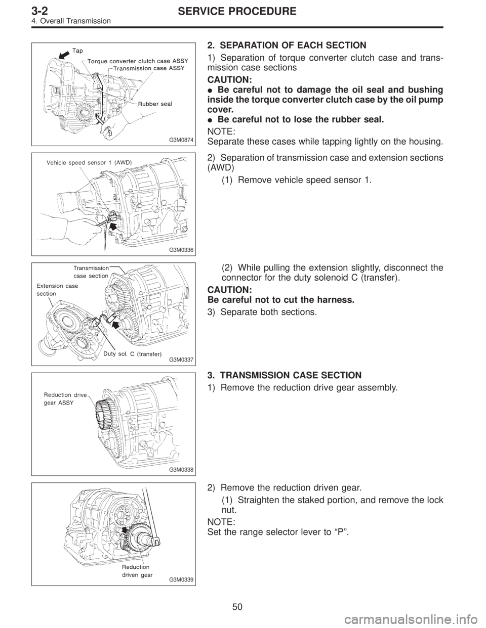
G3M0336
2) Separation of transmission case and extension sections
(AWD)
(1) Remove vehicle speed sensor 1.
G3M0337
(2) While pulling the extension slightly, disconnect the
connector for the duty solenoid C (transfer).
CAUTION:
Be careful not to cut the harness.
3) Separate both sections.
G3M0338
3. TRANSMISSION CASE SECTION
1) Remove the reduction drive gear assembly.
G3M0339
2) Remove the reduction driven gear.
(1) Straighten the staked portion, and remove the lock
nut.
NOTE:
Set the range selector lever to“P”.
50
3-2SERVICE PROCEDURE
4. Overall Transmission
Page 402 of 2248
G3M0371
5) Remove the snap ring. Then remove the speedometer
driven gear.
G3M0372
6) Remove vehicle speed sensor 2.
7) Tap out the speedometer shaft to the outside of the
case, and remove the oil seal.
G3M0373
5. EXTENSION SECTION
1) Take out the transfer clutch by lightly tapping the end of
the rear drive shaft.
CAUTION:
Be careful not to damage the oil seal in the extension.
G3M0867
2) Remove duty solenoid C, transfer valve body and the
transfer pipe.
CAUTION:
�Take out the inlet filter.
�Do not damage the O-ring.
�Be careful not to bend the pipe.
B3M0831A
3) Take out the roller bearing inner race with ST.
ST 398527700 PULLER
4) Take out the roller bearing outer race with ST.
NOTE:
Hook ST in the inner side of the roller bearing outer race.
ST 398527700 PULLER
58
3-2SERVICE PROCEDURE
4. Overall Transmission
Page 403 of 2248
 Check the appearance of each component and clean.
CAUTION:
Make sure each part is free of harmful cuts, damage
and other")
B: ASSEMBLY OF OVERALL TRANSMISSION
1. TORQUE CONVERTER CLUTCH CASE SECTION
1) Check the appearance of each component and clean.
CAUTION:
Make sure each part is free of harmful cuts, damage
and other faults.
G3M0377
2) Install the washer and snap ring to the speedometer
shaft with ST, and set the oil seal. Then force-fit the shaft
to the torque converter clutch case.
ST 499827000 PRESS
3) Install vehicle speed sensor 2.
CAUTION:
Use new vehicle speed sensor 2, if it has been
removed.
Tightening torque:
5.9±1.5 N⋅m (60±15 kg-cm, 52±13 in-lb)
G3M0378
4) Install the speedometer driven gear to the speedometer
shaft, and secure with a snap ring.
G3M0379
5) Force-fit the oil seal to the torque converter clutch case
with ST.
ST 398437700 DRIFT
G3M0380
6) Install the differential assembly to the case, paying spe-
cial attention not to damage the speedometer gears (drive
and driven) and the inside of the case (particularly, the dif-
ferential side retainer contact surface).
59
3-2SERVICE PROCEDURE
4. Overall Transmission
Page 421 of 2248
 Install the transfer clutch assembly to the case.
CAUTION:
Be careful not to damage the seal rings.
NOTE:
Insert the clutch assembly fully into position until the bear-
ing shoulder bottoms")
G3M0894
3) Install the transfer clutch assembly to the case.
CAUTION:
Be careful not to damage the seal rings.
NOTE:
Insert the clutch assembly fully into position until the bear-
ing shoulder bottoms.
G3M0429
6. CONNECTION OF EACH SECTION
1) Install vehicle speed sensor 1 on transmission case.
[FWD only]
Tightening torque:
7±1 N⋅m (0.7±0.1 kg-m, 5.1±0.7 ft-lb)
2) Install oil pipe.
G3M0339
3) Install the reduction driven gear.
4) Install the parking pawl and shaft, set the select lever in
the“P”range and tighten the drive pinion lock nut.
Tightening torque:
98±5 N⋅m (10.0±0.5 kg-m, 72.3±3.6 ft-lb)
NOTE:
After tightening, stake the lock nut securely.
G3M0895
5) Install the reduction drive gear assembly.
CAUTION:
Align mark on reduction drive gear with mark on driven
gear during installation.
NOTE:
Insert it fully into position until the bearing shoulder bot-
toms.
G3M0430
6) Measurement and adjustment of extension end play
(1) Measure distance L from end of extension case and
rear drive shaft with ST. (On FWD models, measure
distance from end of case to point at bearing location.)
ST 398643600 GAUGE
Unit: mm
L = Measured value�15
77
3-2SERVICE PROCEDURE
4. Overall Transmission
Page 423 of 2248
 Installation of extension case (AWD), transmission
cover (FWD) and transmission case.
�AWD model:
(1) Attach the selected thrust needle bearing to the end
surface of reduction drive gear wi")
G3M0896
7) Installation of extension case (AWD), transmission
cover (FWD) and transmission case.
�AWD model:
(1) Attach the selected thrust needle bearing to the end
surface of reduction drive gear with vaseline.
(2) Set the parking return spring.
(3) Remove the transfer clutch from the extension
case.
Set the needle bearing on the reduction drive shaft and
then install transfer clutch to the transfer clutch hub.
NOTE:
Be sure to engage the spline teeth correctly.
(4) With gasket inserted between them, install the
extension case to the transmission case.
CAUTION:
�Be sure to use a new gasket.
�After inserting the extension case halfway, connect
the connector for duty solenoid C. Be careful not to
jam the cord in the case.
�Be careful not to damage the rear drive shaft seal
ring.
(5) Tighten bolts to secure the case.
Tightening torque:
25±2 N⋅m (2.5±0.2 kg-m, 18.1±1.4 ft-lb)
�FWD model:
(1) Attach selected shim to transmission cover using
vaseline.
(2) Set the parking return spring.
(3) After positioning gasket, assemble transmission
cover and transmission case.
NOTE:
While aligning bearings, parking shaft, reduction driven
gear, etc. assemble the two cases.
(4) Tighten bolts.
Tightening torque:
25±2 N⋅m (2.5±0.2 kg-m, 18.1±1.4 ft-lb)
G3M0336
7. EXTERNAL PARTS
1) Install the vehicle speed sensor 1. (AWD only)
Tightening torque:
7±1 N⋅m (0.7±0.1 kg-m, 5.1±0.7 ft-lb)
79
3-2SERVICE PROCEDURE
4. Overall Transmission
 Remove the snap ring. Then remove the speedometer
driven gear.
G3M0372
6) Remove vehicle speed sensor 2.
7) Tap out the speedometer shaft to the outside of the
case, and remove the oil seal")