Page 576 of 2248

E: INSTALLATION
1) Install transverse link ball joint to housing.
Tightening torque:
44±6 N⋅m (4.5±0.6 kg-m, 32.5±4.3 ft-lb)
2) While aligning alignment mark on camber adjusting bolt
head, connect housing and strut.
CAUTION:
Use a new self-locking nut.
Tightening torque:
147±15 N⋅m (15±1.5 kg-m, 108±11 ft-lb)
3) Install speed sensor and harness on housing (only
vehicle equipped with A.B.S.).
4) Install disc rotor on hub.
5) Install disc brake caliper on housing.
Tightening torque:
59±10 N⋅m (6±1 kg-m, 43±7 ft-lb)
6) Install front drive shaft.
7) Connect stabilizer link.
G4M0236
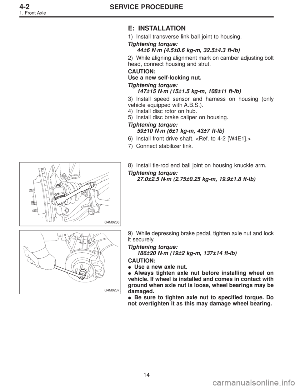
8) Install tie-rod end ball joint on housing knuckle arm.
Tightening torque:
27.0±2.5 N⋅m (2.75±0.25 kg-m, 19.9±1.8 ft-lb)
G4M0237
9) While depressing brake pedal, tighten axle nut and lock
it securely.
Tightening torque:
186±20 N⋅m (19±2 kg-m, 137±14 ft-lb)
CAUTION:
�Use a new axle nut.
�Always tighten axle nut before installing wheel on
vehicle. If wheel is installed and comes in contact with
ground when axle nut is loose, wheel bearings may be
damaged.
�Be sure to tighten axle nut to specified torque. Do
not overtighten it as this may damage wheel bearing.
14
4-2SERVICE PROCEDURE
1. Front Axle
Page 584 of 2248
E: INSTALLATION
1) Connect rear housing assembly and strut assembly.
CAUTION:
Use a new self-locking nut.
Tightening torque:
147±15 N⋅m (15±1.5 kg-m, 108±11 ft-lb)
2) Fit BJ (bell joint) to rear housing splines.
CAUTION:
Be careful not to damage inner oil seal lip.
G4M0245
3) Connect rear housing assembly to lateral link assembly.
CAUTION:
Use a new self-locking nut.
Tightening torque:
137±20 N⋅m (14±2 kg-m, 101±14 ft-lb)
G4M0246
4) Connect rear housing assembly to trailing link assem-
bly.
CAUTION:
Use a new self-locking nut.
Tightening torque:
98 — 127 N⋅m (10 — 13 kg-m, 72 — 94 ft-lb)
5) Connect parking brake cable to parking brake.
Disc brake: Perform steps 6) through 8).
6) Install disc rotor on rear housing assembly.
G4M0240
7) Install disc brake caliper on back plate.
Tightening torque:
52±6 N⋅m (5.3±0.6 kg-m, 38.3±4.3 ft-lb)
G4M0266
8) Install rear speed sensor to back plate (only vehicle
equipped with A.B.S.).
21
4-2SERVICE PROCEDURE
2. Rear Axle (AWD Model)
Page 779 of 2248
B4M0248
2) Measure ABS sensor resistance.
ABS sensor Terminal No. Standard
Front - LH 1 and 2
1.0±0.2 kΩ Front - RH 1 and 2
Rear - LH 1 and 2
Rear - RH 1 and 2
CAUTION:
If resistance is outside the standard value, replace
ABS sensor with new one.
NOTE:
Check ABS sensor cable for discontinuity. If necessary,
replace with a new one.
G4M0448
2. TONE WHEEL
1) Check tone wheel’s teeth (44 pieces) for cracks or
dents. If necessary, replace tone wheel with a new one.
2) Clearances (sensor gaps) should be measured one by
one to ensure tone wheel and speed sensor are installed
correctly.
ABS sensor clearance:
Front
0.9—1.4 mm (0.035—0.055 in)
Rear
0.7—1.2 mm (0.028—0.047 in)
NOTE:
�If clearance is narrow, adjust by using spacer (Part No.
26755AA000).
�If clearance is wide, check the outputted voltage then
replace ABS sensor or tone wheel if the outputted voltage
is outside the specification.
62
4-4SERVICE PROCEDURE
14. ABS Sensor
Page 1136 of 2248

14. Vehicle Speed Sensor 2
A: GENERAL PRECAUTIONS
1) Be careful not to drop or bump sensor as this may break
built-in magnet.
2) Drive key is designed to separate from vehicle speed
sensor 2. Be careful not to lose it or forget to install.
3) Vehicle speed sensor 2 is installed in part (which con-
tains bearings, etc., finished to a high degree of accuracy).
Do not allow foreign matter (filings, sand, etc.) to get into
it.
4) When checking output of vehicle speed sensor 2 as a
single unit, ensure test leads are connected to their correct
terminals. Failure to do this may damage internal IC.
5) Discard vehicle speed sensor 2 after removal; replace
with new one.
B: REMOVAL
CAUTION:
�Be careful when removing vehicle speed sensor 2
immediately after driving vehicle for a while, as tem-
perature around it is high.
�Before removing vehicle speed sensor 2, clean dirt,
etc. from surrounding areas. Take care not to allow
foreign matter to get into mounting hole.
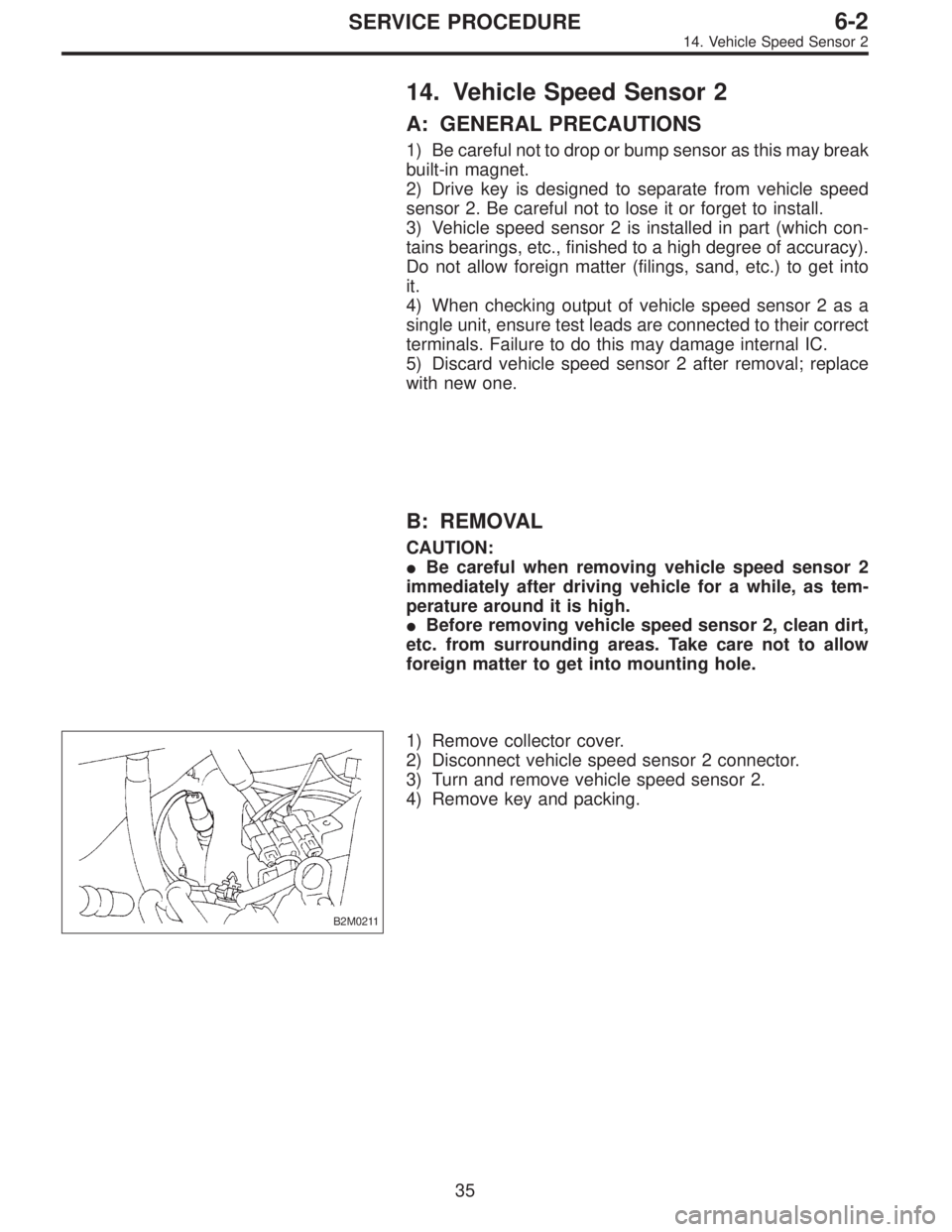
B2M0211
1) Remove collector cover.
2) Disconnect vehicle speed sensor 2 connector.
3) Turn and remove vehicle speed sensor 2.
4) Remove key and packing.
35
6-2SERVICE PROCEDURE
14. Vehicle Speed Sensor 2
Page 1137 of 2248
C: INSTALLATION
CAUTION:
�Ensure sensor mounting hole is clean and free of
foreign matter.
�Apply grease to tip end of key to prevent key from
falling off sensor.
�Align tip end of key with key groove on end of
speedometer shaft during installation.
1) Hand tighten vehicle speed sensor 2, then tighten it
using suitable tool.
Tightening torque required for sensor to reach bottom of
transmission is as follows:
Tightening torque:
0.39—0.88 N⋅m (4.0—9.0 kg-cm, 3.5—7.8 in-lb)
CAUTION:
�When torque must be applied that exceeds 0.88 N⋅m
(9.0 kg-cm, 7.8 in-lb), the key and key groove on end of
speedometer may not be aligned properly. Remove the
key, align it correctly and reassemble.
�Sensor threads are secured by Locktite. The reas-
sembly must be completed within 5 minutes before
Locktite dries.
2) Tighten vehicle speed sensor 2 further to specified
torque.
Tightening torque:
5.9±1.5 N⋅m (60±15 kg-cm, 52±13 in-lb)
36
6-2SERVICE PROCEDURE
14. Vehicle Speed Sensor 2
Page 1174 of 2248
3. Combination Meter
A: DIAGNOSTICS PROCEDURE
If speedometer does not operate, or operates abnormally,
check combination meter circuit (shown in flow chart as
described below).
CAUTION:
Make sure that trouble code of vehicle speed sensor 2
system appears in electrical system on-board diagno-
sis.
Speedometer does not operate, or operates
abnormally.
1. Check power supply for combination meter.
OK
�Not OK
�Check for disconnection of the combination meter
connector terminal.
�Check for open circuit between combination meter
and battery.
,Repair or replace wiring harness.
2. Check ground circuit of combination meter.
OK
�Not OK
Repair or replace wiring harness.
3. Check harness connector between
combination meter and vehicle speed sensor
2.
OK
�Not OK
Repair or replace wiring harness.
4. Check vehicle speed sensor 2.
OK
�Not OK
Replace vehicle speed sensor 2.
Failure of the speedometer.
�
�
�
�
�
70
6-2DIAGNOSTICS
3. Combination Meter
Page 1175 of 2248

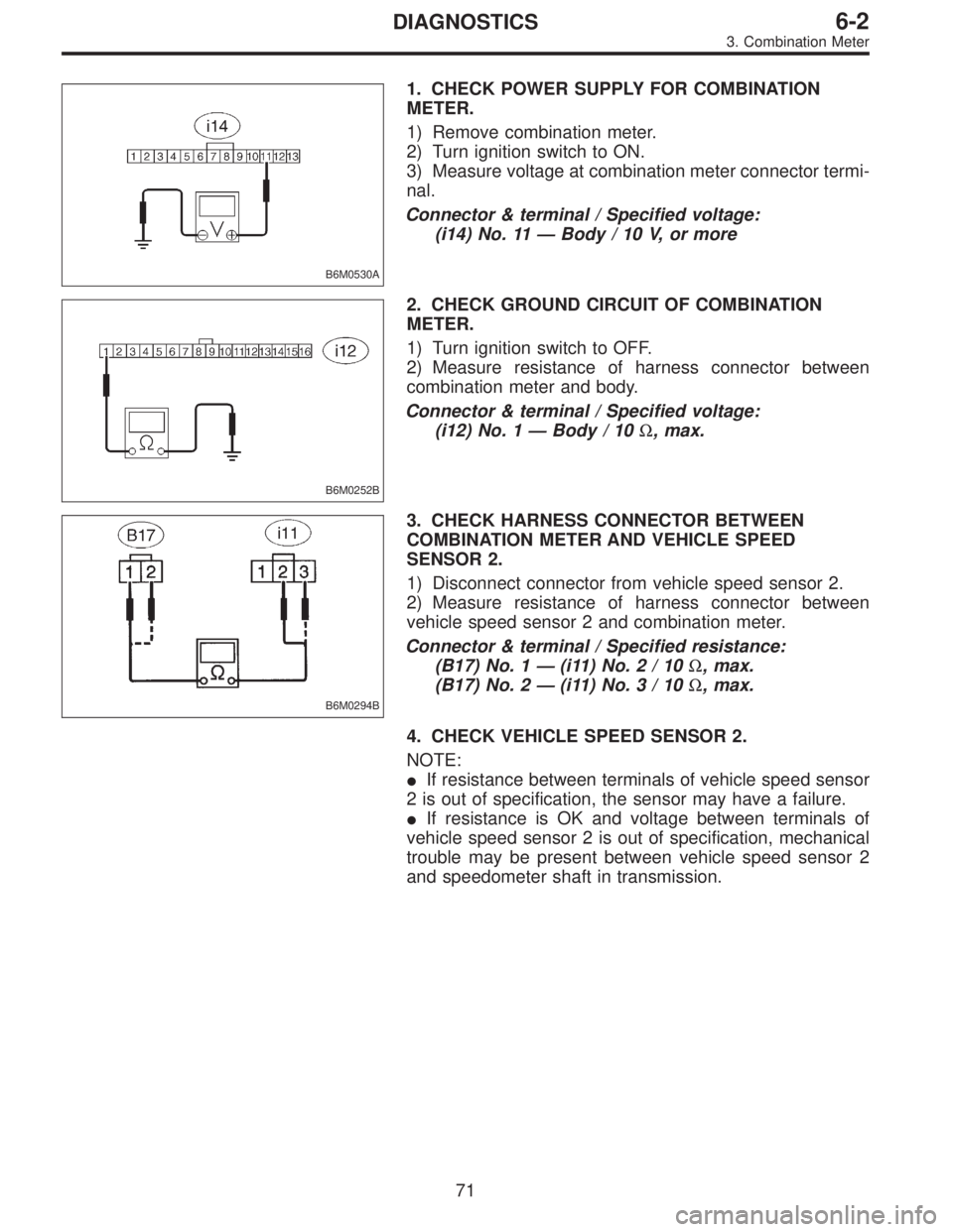
B6M0530A
1. CHECK POWER SUPPLY FOR COMBINATION
METER.
1) Remove combination meter.
2) Turn ignition switch to ON.
3) Measure voltage at combination meter connector termi-
nal.
Connector & terminal / Specified voltage:
(i14) No. 11—Body / 10 V, or more
B6M0252B
2. CHECK GROUND CIRCUIT OF COMBINATION
METER.
1) Turn ignition switch to OFF.
2) Measure resistance of harness connector between
combination meter and body.
Connector & terminal / Specified voltage:
(i12) No. 1—Body / 10Ω, max.
B6M0294B
3. CHECK HARNESS CONNECTOR BETWEEN
COMBINATION METER AND VEHICLE SPEED
SENSOR 2.
1) Disconnect connector from vehicle speed sensor 2.
2) Measure resistance of harness connector between
vehicle speed sensor 2 and combination meter.
Connector & terminal / Specified resistance:
(B17) No. 1—(i11)No.2/10Ω, max.
(B17) No. 2—(i11)No.3/10Ω, max.
4. CHECK VEHICLE SPEED SENSOR 2.
NOTE:
�If resistance between terminals of vehicle speed sensor
2 is out of specification, the sensor may have a failure.
�If resistance is OK and voltage between terminals of
vehicle speed sensor 2 is out of specification, mechanical
trouble may be present between vehicle speed sensor 2
and speedometer shaft in transmission.
71
6-2DIAGNOSTICS
3. Combination Meter
Page 1176 of 2248
B3M0289
1) Disconnect connector from vehicle speed sensor 2.
2) Measure resistance between terminals of vehicle speed
sensor 2.
Terminals / Specified resistance:
No. 1—No. 2 / 350—450Ω
B3M0256
WARNING:
Be careful not to be caught up by the running wheels.
3) Set the vehicle on free roller, or lift-up the vehicle and
support with safety stands.
4) Drive the vehicle at speed greater than 20 km/h (12
MPH).
5) Measure voltage between terminals of vehicle speed
sensor 2.
Terminals / Specified voltage:
No. 1—No.2/5V,min. (AC range)
B3M0257
�Using an oscilloscope:
(1) Turn ignition switch to OFF.
(2) Set oscilloscope to vehicle speed sensor 2.
(3) Drive the vehicle at speed greater than 20 km/h (12
MPH).
(4) Measure signal voltage.
Specified voltage (V): 5 V, min.
B3M0254A
72
6-2DIAGNOSTICS
3. Combination Meter