Page 1562 of 2248
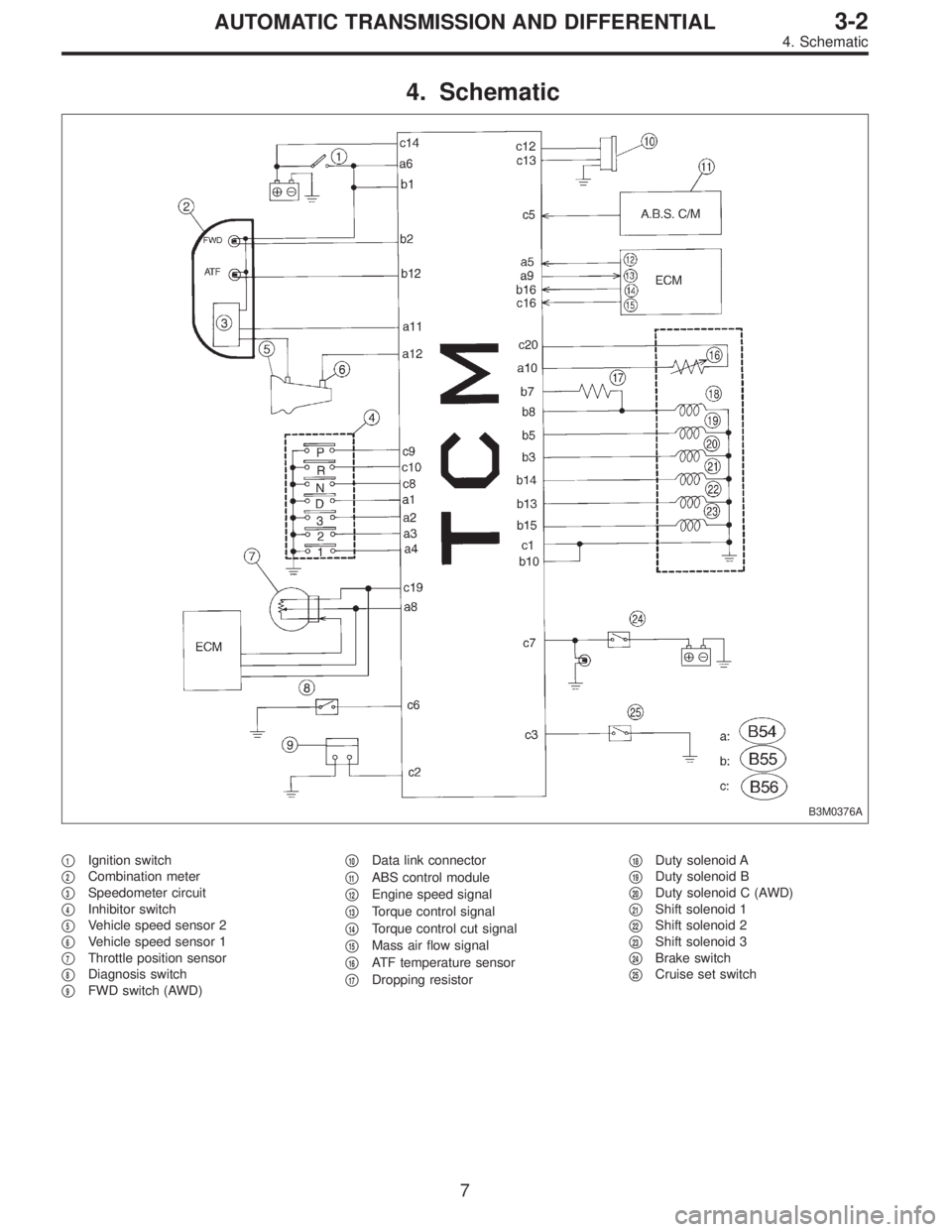
4. Schematic
B3M0376A
�1Ignition switch
�
2Combination meter
�
3Speedometer circuit
�
4Inhibitor switch
�
5Vehicle speed sensor 2
�
6Vehicle speed sensor 1
�
7Throttle position sensor
�
8Diagnosis switch
�
9FWD switch (AWD)�
10Data link connector
�
11ABS control module
�
12Engine speed signal
�
13Torque control signal
�
14Torque control cut signal
�
15Mass air flow signal
�
16ATF temperature sensor
�
17Dropping resistor�
18Duty solenoid A
�
19Duty solenoid B
�
20Duty solenoid C (AWD)
�
21Shift solenoid 1
�
22Shift solenoid 2
�
23Shift solenoid 3
�
24Brake switch
�
25Cruise set switch
7
3-2AUTOMATIC TRANSMISSION AND DIFFERENTIAL
4. Schematic
Page 1564 of 2248
Resistance to
body
(ohms)
Throttle position
sensorB54 8Throttle fully closed. 0.5±0.2
—
Throttle fully open. 4.6±0.3
Throttle positio")
ContentConnector
No.Terminal
No.Measuring conditionsVoltage
(V)Resistance to
body
(ohms)
Throttle position
sensorB54 8Throttle fully closed. 0.5±0.2
—
Throttle fully open. 4.6±0.3
Throttle position
sensor power
supplyB56 19Ignition switch ON
(With engine OFF)5.05±0.25—
ATF temperature
sensorB54 10ATF temperature 20°C(68°F) 3.45±0.55 2.1—2.9 k
ATF temperature 80°C (176°F) 1.2±0.2 275—375
Vehicle speed
sensor 1B54 12Vehicle stopped. 0
450—720
Vehicle speed at least 20 km/h (12
MPH)More than 1 (AC range)
Vehicle speed
sensor 2B56 11When vehicle is slowly moved at
least 2 meters (7ft).Less than 1)More than 9—
Engine speed
signalB54 5Ignition switch ON (with engine
OFF).More than 10.5
—
Ignition switch ON (with engine ON). 8—11
Cruise set signal B56 3When cruise control is set (SET
lamp ON).Less than 1
—
When cruise control is not set (SET
lamp OFF).More than 6.5
Torque control
signalB55 16 Ignition switch ON 5±1—
Torque control cut
signalB56 16 Ignition switch ON 6—9—
Mass air flow
signalB54 9 Engine idling after warm-up 0.5—1.2—
Shift solenoid 1 B55 141st or 4th gear More than 9
20—32
2nd or 3rd gear Less than 1
Shift solenoid 2 B55 131st or 2nd gear More than 9
20—32
3rd or 4th gear Less than 1
Shift solenoid 3 B55 15Select lever in“N”range (with
throttle fully closed).Less than 1
20—32
Select lever in“D”range (with
throttle fully closed).More than 9
Duty solenoid A B55 8Throttle fully closed (with engine
OFF) after warm-up.1.5—4.0
2.0—4.5
Throttle fully open (with engine
OFF) after warm-up.Less than 1
Dropping resistor B55 7Throttle fully closed (with engine
OFF) after warm-up.More than 8.5
12—18
Throttle fully open (with engine
OFF) after warm-up.Less than 1
Duty solenoid B B55 5When lock up occurs. More than 8.5
9—17
When lock up is released. Less than 0.5
Duty solenoid C
(AWD model only)B55 3Fuse on FWD switch More than 8.5
9—17 Fuse removed from FWD switch
(with throttle fully open and with
select lever in 1st gear).Less than 0.5
Sensor ground
line 1B54 7—0 Less than 1
Sensor ground
line 2B56 20—0 Less than 1
System ground
lineB56 1—0 Less than 1
Power system
ground lineB55 10—0 Less than 1
FWD switch
(AWD model only)B56 2Fuse removed. 6—9.1
—
Fuse installed. Less than 1
9
3-2AUTOMATIC TRANSMISSION AND DIFFERENTIAL
5. Transmission Control Module (TCM) I/O Signal
Page 1568 of 2248
Page
11 Duty solenoid ADetects open or shorted drive
circuit, as well as valve seizure.PLDTY 16
12 D")
D: LIST OF TROUBLE CODE
1. TROUBLE CODE
Trouble code Item Content of diagnosisAbbr.
(Select monitor)Page
11 Duty solenoid ADetects open or shorted drive
circuit, as well as valve seizure.PLDTY 16
12 Duty solenoid BDetects open or shorted drive
circuit, as well as valve seizure.LUDTY 20
13 Shift solenoid 3Detects open or shorted drive
circuit, as well as valve seizure.OVR 24
14 Shift solenoid 2Detects open or shorted drive
circuit, as well as valve seizure.SFT2 26
15 Shift solenoid 1Detects open or shorted drive
circuit, as well as valve seizure.SFT1 28
16 Torque control cut signalDetects open or shorted input
signal circuit.TQ.DS 30
21 ATF temperature sensorDetects open or shorted input
signal circuit.ATFT 32
22 Mass air flow signalDetects open or shorted input
signal circuit.AFM 36
23 Engine speed signalDetects open or shorted input
signal circuit.EREV 38
24 Duty solenoid CDetects open or shorted drive
circuit, as well as valve seizure.4WDTY 40
25 Torque control signalDetects open or shorted input
signal circuit.TQ.CT 42
31 Throttle position sensorDetects open or shorted input
signal circuit.THV 44
32 Vehicle speed sensor 1Detects open or shorted input
signal circuit.VSP1 48
33 Vehicle speed sensor 2Detects open or shorted input
signal circuit.VSP2 52
13
3-2AUTOMATIC TRANSMISSION AND DIFFERENTIAL
6. Diagnostic Chart for On-board Diagnostic System
Page 1600 of 2248
M: TROUBLE CODE 32
—VEHICLE SPEED SENSOR 1—
DIAGNOSIS:
Input signal circuit of TCM is open or shorted.
TROUBLE SYMPTOM:
No locking-up or excessive tight corner“braking”
1. Check harness connector between TCM and
vehicle speed sensor 1.
OK
�Not OK
Repair or replace harness connectors.
2. Check vehicle speed sensor 1.
OK
�Not OK
Replace vehicle speed sensor 1.
3. Check input signal for TCM.
OK
�Not OK
�Repair TCM connector terminal poor contact.
�Replace TCM.
When trouble code 32 reappears.
Mechanical trouble between vehicle speed sensor 1
and sprocket
B3M0412
�
�
�
45
3-2AUTOMATIC TRANSMISSION AND DIFFERENTIAL
7. Diagnostic Chart with Trouble Code
Page 1601 of 2248
 Turn ignition switch to OFF.
2) Disconnect connectors from TCM and transmission.
3) Measure resistance of harness connect")
OBD0400A
1. CHECK HARNESS CONNECTOR BETWEEN TCM
AND VEHICLE SPEED SENSOR 1.
1) Turn ignition switch to OFF.
2) Disconnect connectors from TCM and transmission.
3) Measure resistance of harness connector between
TCM and transmission connector.
Connector & terminal / Specified resistance:
(B54) No. 12—(B11) No. 16 / 1Ω, or less
(B54) No. 7—(B11)No.9/1Ω, or less
OBD0401A
4) Measure resistance of harness connector between
TCM and body to make sure that circuit does not short.
Connector & terminal / Specified resistance:
(B54) No. 7—Body/1MΩ, or more
(B54) No. 12—Body/1MΩ, or more
G3M0140
2. CHECK VEHICLE SPEED SENSOR 1.
1) Measure resistance between transmission connector
receptacle’s terminals.
Connector & terminal / Specified resistance:
(T4) No. 16—No. 9 / 450—720Ω
OBD0403A
2) Measure resistance of harness connector between
transmission connector and transmission case to make
sure that circuit does not short.
Connector & terminal / Specified resistance:
(T4) No. 16—Transmission / 1 MΩ, or more
(T4) No. 9—Transmission / 1 MΩ, or more
46
3-2AUTOMATIC TRANSMISSION AND DIFFERENTIAL
7. Diagnostic Chart with Trouble Code
Page 1604 of 2248

N: TROUBLE CODE 33
—VEHICLE SPEED SENSOR 2—
DIAGNOSIS:
�The vehicle speed signal is abnormal.
�The circuit in combination meter is faulty.
�The harness connector between TCM and vehicle speed
sensor is in short or open.
TROUBLE SYMPTOM:
�Erroneous idling
�Engine stalls.
�Poor driving performance
1. Check operation of speedometer.
OK
�Not OK
Check combination meter circuit.
2. Check harness connector between TCM and
combination meter.
OK
�Not OK
Repair or replace harness connector.
3. Check vehicle speed sensor 2.
OK
�Not OK
�Mechanical trouble between vehicle speed sensor
2 and speedometer shaft in transmission
�Failure of the vehicle speed sensor 2
,Replace vehicle speed sensor 2.
4. Check input signal for TCM.
OK
�Not OK
�Repair TCM connector terminal poor contact.
�Replace TCM.
When trouble code 33 reappears after clearing
memory, repair TCM connector terminal poor
contact.
B3M0372
�
�
�
�
49
3-2AUTOMATIC TRANSMISSION AND DIFFERENTIAL
7. Diagnostic Chart with Trouble Code
Page 1606 of 2248
 Install combination meter.
2) Connect connector to TCM.
3) Lift-up the vehicle and place safety stand.
CAUTION:
On AWD models, raise all wheels off floor.
4")
B3M0289
3. CHECK VEHICLE SPEED SENSOR 2.
1) Install combination meter.
2) Connect connector to TCM.
3) Lift-up the vehicle and place safety stand.
CAUTION:
On AWD models, raise all wheels off floor.
4) Disconnect connector from vehicle speed sensor 2.
5) Measure resistance between terminals of vehicle speed
sensor 2.
Terminals / Specified resistance:
(B17) No. 1—No. 2 / 350—450Ω
No. 1—Body/1MΩ, or more
No. 2—Body/1MΩ, or more
B3M0256
6) Push the TCS OFF switch to ON. (With TCS models)
7) Start the engine and set vehicle in 20 km/h (12 MPH)
condition.
8) Measure output signal of vehicle speed sensor 2.
WARNING:
Be careful not to be caught up by the running wheels.
9) Using a voltage meter; measure voltage between termi-
nals of vehicle speed sensor 2.
Terminals / Specified voltage:
(B17) No. 1—No. 2 / AC 2 V, or more
NOTE:
The speed difference between front and rear wheels may
light either the ABS or the ABS/TCS warning light, but this
indicates no malfunctions. When AT control diagnosis is
finished, perform the ABS or the ABS/TCS memory clear-
ance procedure of self-diagnosis system.
51
3-2AUTOMATIC TRANSMISSION AND DIFFERENTIAL
7. Diagnostic Chart with Trouble Code
Page 1607 of 2248
 Install combination meter.
(2) Connect connector to TCM.
(3) Lift-up the vehicle and place safety stand.
WARNING:
On AWD models, make sure that all wheels are raised
o")
B3M0257
�Using oscilloscope:
(1) Install combination meter.
(2) Connect connector to TCM.
(3) Lift-up the vehicle and place safety stand.
WARNING:
On AWD models, make sure that all wheels are raised
off floor.
(4) Set oscilloscope to vehicle speed sensor 2.
Connector & terminal / No. 1—No. 2
B3M0254A
(5) Push the TCS OFF switch to ON. (With TCS mod-
els)
(6) Start the engine, and drive the wheels slowly.
(7) Measure signal voltage indicated on oscilloscope.
Specified voltage: AC 2 V, or more
NOTE:
The speed difference between front and rear wheels may
light either the ABS or the ABS/TCS warning light, but this
indicates no malfunctions. When AT control diagnosis is
finished, perform the ABS or the ABS/TCS memory clear-
ance procedure of self-diagnosis system.
B3M0369A
4. CHECK INPUT SIGNAL FOR TCM.
1) Connect connector to vehicle speed sensor 2.
2) Lift-up the vehicle or set the vehicle on free roller.
CAUTION:
On AWD models, raise all wheels off floor.
3) Push the TCS OFF switch to ON. (With TCS models)
4) Start the engine, and drive the wheels slowly.
5) Measure voltage between TCM and body.
Connector & terminal / Specified voltage:
(B56) No. 11—Body / Less than 1↔
more than 9 V
NOTE:
The speed difference between front and rear wheels may
light either the ABS or the ABS/TCS warning light, but this
indicates no malfunctions. When AT control diagnosis is
finished, perform the ABS or the ABS/TCS memory clear-
ance procedure of self-diagnosis system.
52
3-2AUTOMATIC TRANSMISSION AND DIFFERENTIAL
7. Diagnostic Chart with Trouble Code