Page 1808 of 2248

11. General Diagnostics Table
��: Primary expected causes�: Secondary expected causes
Trouble conditions
SymptomsHydraulic
unit
Speed sensor
P valve
Master cylinder
Calipers and piston
Pad
Rotor
Hand brake
Piping
Mixture of air
Brake booster and check valve
Axle and wheel
Alignment
Play of pedal
Rough road surface
Semicylindrical road surface
Loose or worn suspension
Tire
Wrong connection and wiring
Stroke sensor Solenoid valve
Motor
Mount bush ABS function
Directional stability cannot be
obtained when braking.Vehicle turns to right or left.����������� ������������
Vehicle spins.�������������
Out-of-order brakesLong braking distance
��� ���������������
Brakes lock.������� � ��
Brakes drag.�����������������
Long pedal stroke� ���� �����
Abnormal vehicle pitching�� ������
Unstable braking force. One-
side brake refuses to work.����������� ����������
TCS function
When accelerating abruptly,
directional stability cannot be
obtained when traveling on a
slippery road surface.Vehicle moves unsteadily.������������������
Handle refuses to work.�������������
Handle loses control.���������� ���������
Bad acceleration, engine stall-
ing (In addition to the causes
listed here, check the ECM
specifications.)Engine stalls. Engine speed
fails to increase.�����������
Engine speed increases sud-
denly.��������������������
Vibration occurs and abnormal
noise is produced.
�When applying brakes abruptly.
�When accelerating abruptly.
�When driving on a slippery
road surface.Brake pedal heavily vibrates
when applying brakes.
�� � � �������
Loud hydraulic unit operating
noise��������
Noise is produced from front
of vehicle.���������������������
Noise is produced from rear of
vehicle.����������������
NOTE:
This list includes no engine failure and transmission failure.
127
4-4bBRAKES
11. General Diagnostics Table
Page 1810 of 2248

6. INSPECTOR
Before advancing the vehicle after the engine starts, drive
the pump motor and valve for a very short time to function-
ally check the ABS/TCS brakes. It is not abnormal if, at this
time, operating noises of the valve and motor are produced
or kickback of the brake pedal is felt when stepping on the
pedal.
7. WHEN ATTACHING CHAINS
It is sometimes a good idea to turn off the TCS for better
advancing and accelerating the vehicle.
8. WHEN A DRUM TESTER IS USED (SPEEDOMETER
TEST, EXHAUST GAS TEST, BRAKE TEST, ETC.)
Before performing tests, turn the TCS off by operating the
TCS OFF switch or disconnect the fuse of ECM input
power source to put the machine out of operation. If oper-
ating other parts to put the TCS in the fail state
intentionally, trouble code will be recorded. Make sure to
clear the memory. Also, in a 2-wheel tester, wheel speed
sensor failure can be detected, making the TCS fail. This
case is also not abnormal and clearing the memory is
required.
129
4-4bBRAKES
12. Phenomena Peculiar to the System
Page 1860 of 2248

Main power supply 2�Battery voltage is present when main power is tu")
5. Control Module I/O Signal
G6M0015
ContentTerminal
No.Measuring conditions and I/O signals (ignition switch ON and engine idling)
Main power supply 2�Battery voltage is present when main power is turned ON.
�“0”volt is present when main power is turned OFF.
Inhibitor switch (AT) (U.S.A.)
N position switch (AT) (CANADA)4�“0”volt is present when selector lever is set to P or N position (CANADA: N position only).
�Battery voltage is present when selector lever is other than P or N position (CANADA: N
position only).
Air valve 5�“0”volt is present when vehicle is stopped.
�ON-and-OFF (“0”-and-battery voltage) operation is alternately repeated while cruise control
is operating.
GND 6—
Vacuum pump motor 7�“0”volt is present when vehicle is stopped.
�ON-and-OFF (“0”-and-battery voltage) operation is alternately repeated while cruise control
is operating.
Data link connector 8—
RESUME/ACCEL switch 9�Battery voltage is present when switch is turned ON.
�“0”volt is present when switch is turned OFF.
SET/COAST switch 10�Battery voltage is present when switch is turned ON.
�“0”volt is present when switch is turned OFF.
Ignition switch 12�Battery voltage is present when ignition switch is turned ON.
�“0”volt is present when ignition switch is turned OFF.
Release valve 13�“0”volt is present when vehicle is stopped.
�ON-and-OFF (“0”-and-battery voltage) operation is alternately repeated while cruise control
is operating.
Power supply to vacuum pump
motor, air valve, release valve14�“0”volt is present when vehicle is stopped.
�Battery voltage is present while cruise control is operating.
Cruise main switch 15�Battery voltage is present during pressing the main switch, and then approx. 12 V is
present while switch is turned ON.
�“0”volt is present when switch is turned OFF.
Brake switch 16Turn the cruise main switch to ON and leave clutch pedal released (MT).
Then check that;
�“0”volt is present when brake pedal is depressed.
�Battery voltage is present when brake pedal is released.
Additionally only in MT vehicle, keep the cruise main switch to ON and leave brake pedal
released.
Then check that;
�“0”volt is present when clutch pedal is depressed.
�Battery voltage is present when clutch pedal is released.
Data link connector 17—
Data link connector 18—
Vehicle speed sensor 2 19Lift-up the vehicle until all four wheels are raised off ground, and then rotate any wheel manu-
ally.
Approx. 5 and 0 volt pulse signals are alternately input to cruise control module.
Stop light switch 20Turn ignition switch to OFF.
Then check that;
�Battery voltage is present when brake pedal is depressed.
�“0”volt is present when brake pedal is released.
NOTE:
Voltage at terminals 5, 7, 13 and 14 cannot be checked unless vehicle is driving by cruise control operation.
7
6-2BODY ELECTRICAL SYSTEM
5. Control Module I/O Signal
Page 1862 of 2248

B: ON-BOARD DIAGNOSIS WITH SELECT
MONITOR
1. GENERAL
The on-board diagnosis function of the cruise control sys-
tem uses an external select monitor.
The on-board diagnosis function operates in two
categories, which are used depending on the type of prob-
lems;
�Cruise cancel conditions diagnosis
�Real-time diagnosis
Applicable cartridge No.: 498349601
�Cruise cancel conditions diagnosis
This category of diagnosis requires actual vehicle driv-
ing in order to determine the cause, (as when cruise
speed is cancelled during driving although cruise cancel
condition is not entered).
Cruise control module memory stores the cancel condi-
tion (Code No.) which occurred during driving. When
there are plural cancel conditions (Code No.), they are
shown in order, for 2 seconds per Code No., on the
select monitor.
CAUTION:
�The cruise control memory stores not only the
cruise“cancel”which occurred (although“cancel”
operation is not entered by the driver), but also the
“cancel”condition input by the driver.
�The content of memory is cleared when ignition
switch or cruise main switch is turned OFF.
�Real-time diagnosis
The real-time diagnosis function is used to determine
whether or not the input of output signal system is in good
order, according to signal emitted from switches, sensors,
etc.
Vehicle cannot be driven at cruise speed because prob-
lems occurs in the cruise control system or its associ-
ated circuits.
Monitor the signal conditions from switches and sen-
sors.
9
6-2BODY ELECTRICAL SYSTEM
6. Diagnostics Chart for On-board Diagnosis System
Page 1869 of 2248

8. Diagnostics Chart with Trouble Code
A: TROUBLE CODE
Trouble code Item Contents of diagnosis Page
10 OK Normal 18
11 BRAKE/ST/CL or N�Input signals from brake switch“OFF”, stop light
switch“ON”(Brake pedal is in depressed condi-
tion.)
�Input signals from clutch switch“OFF”, or inhibi-
tor switch is in“N”position.
[Clutch pedal is depressed (MT), or select lever
is set to N position (AT).]20
12 NOT SET SP Out of cruise speed range 22
13 LOW SP LIM Low-speed control limiter 22
14 CANCEL SW Input signal from cancel switch 26
15 NO MEMORY No memorized cruise speed—
21 SP SENS NG Faulty vehicle speed sensor 2 22
22 COM SW NGFaulty SET/COAST switch or RESUME/ACCEL
switch26
23 RELAY NG Faulty safety relay included in cruise control module 29
24 CPU RAM NG Faulty CPU RAM included in cruise control module 29
31 MOTOR NG Faulty vacuum motor or motor drive system 30
32 AIR VAL NG Faulty air valve or valve drive system 30
33 REL VAL NG Faulty release valve or valve drive system 30
16
6-2BODY ELECTRICAL SYSTEM
8. Diagnostics Chart with Trouble Code
Page 1875 of 2248
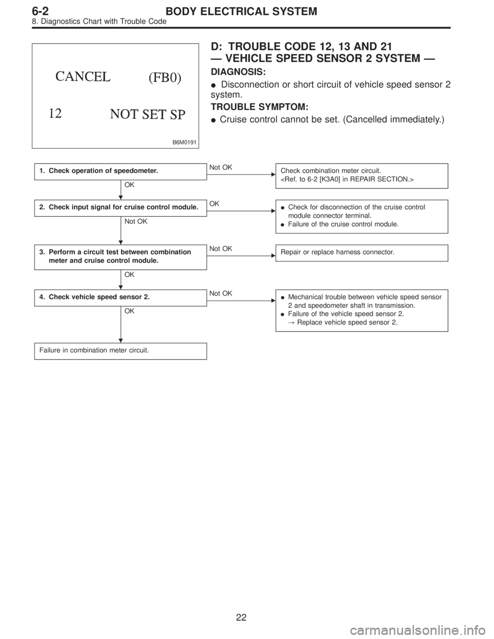
B6M0191
D: TROUBLE CODE 12, 13 AND 21
—VEHICLE SPEED SENSOR 2 SYSTEM—
DIAGNOSIS:
�Disconnection or short circuit of vehicle speed sensor 2
system.
TROUBLE SYMPTOM:
�Cruise control cannot be set. (Cancelled immediately.)
1. Check operation of speedometer.
OK
�Not OK
Check combination meter circuit.
2. Check input signal for cruise control module.
Not OK
�OK
�Check for disconnection of the cruise control
module connector terminal.
�Failure of the cruise control module.
3. Perform a circuit test between combination
meter and cruise control module.
OK
�Not OK
Repair or replace harness connector.
4. Check vehicle speed sensor 2.
OK
�Not OK
�Mechanical trouble between vehicle speed sensor
2 and speedometer shaft in transmission.
�Failure of the vehicle speed sensor 2.
,Replace vehicle speed sensor 2.
Failure in combination meter circuit.
�
�
�
�
22
6-2BODY ELECTRICAL SYSTEM
8. Diagnostics Chart with Trouble Code
Page 1878 of 2248
 Measure resistance of harness connector between
cruise control module and body to make sure that circuit
does not short.
Connector & terminal / Specified resistance:
(B94) No. 19—Body /")
B6M0248B
5) Measure resistance of harness connector between
cruise control module and body to make sure that circuit
does not short.
Connector & terminal / Specified resistance:
(B94) No. 19—Body / 1 MΩ, min.
B3M0289
4. CHECK VEHICLE SPEED SENSOR 2.
1) Disconnect connector from vehicle speed sensor 2.
2) Measure resistance between terminals of vehicle speed
sensor 2.
Terminals / Specified resistance:
No. 1—No. 2 / 350—450Ω
B3M0256
WARNING:
Be careful not to be caught up by the running wheels.
3) Set the vehicle on free roller, or lift-up the vehicle and
support with safety stands.
4) Drive the vehicle at speed greater than 20 km/h (12
MPH).
5) Measure voltage between terminals of vehicle speed
sensor 2.
Terminals / Specified voltage:
No. 1—No. 2 / 2 V, or more (AC range)
B3M0257
�Using an oscilloscope:
(1) Turn ignition switch to OFF.
(2) Set oscilloscope to vehicle speed sensor 2.
(3) Drive the vehicle at speed greater than 20 km/h (12
MPH).
(4) Measure signal voltage.
Specified voltage (V): 5 V, min.
B3M0254A
25
6-2BODY ELECTRICAL SYSTEM
8. Diagnostics Chart with Trouble Code
Page 1885 of 2248
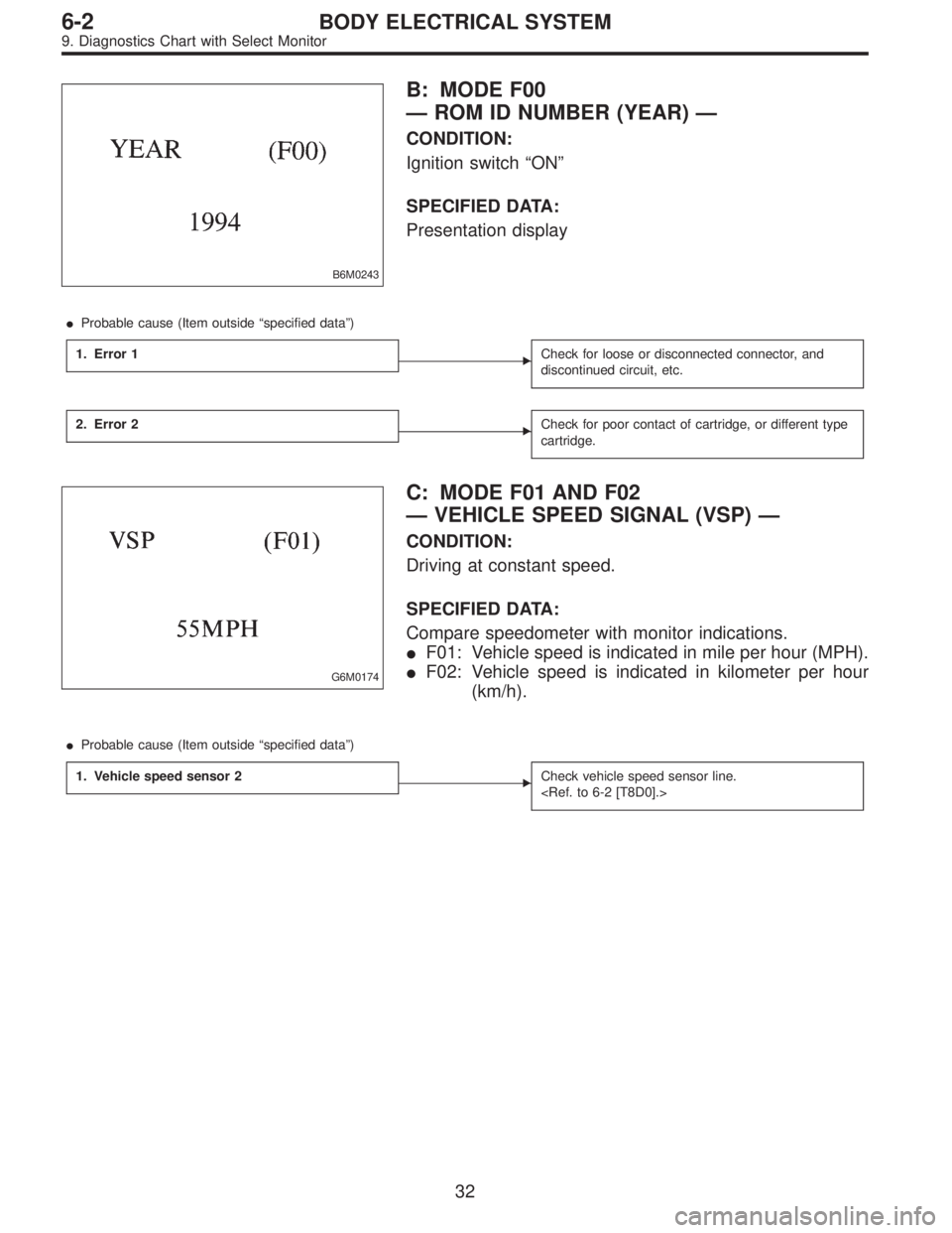
B6M0243
B: MODE F00
—ROM ID NUMBER (YEAR)—
CONDITION:
Ignition switch“ON”
SPECIFIED DATA:
Presentation display
�Probable cause (Item outside“specified data”)
1. Error 1
�Check for loose or disconnected connector, and
discontinued circuit, etc.
2. Error 2�Check for poor contact of cartridge, or different type
cartridge.
G6M0174
C: MODE F01 AND F02
—VEHICLE SPEED SIGNAL (VSP)—
CONDITION:
Driving at constant speed.
SPECIFIED DATA:
Compare speedometer with monitor indications.
�F01: Vehicle speed is indicated in mile per hour (MPH).
�F02: Vehicle speed is indicated in kilometer per hour
(km/h).
�Probable cause (Item outside“specified data”)
1. Vehicle speed sensor 2
�Check vehicle speed sensor line.
32
6-2BODY ELECTRICAL SYSTEM
9. Diagnostics Chart with Select Monitor