Page 1608 of 2248
 Install combination meter.
(2) Connect connectors to TCM and vehicle speed
sensor 2.
(3) Lift-up the vehicle or set the vehicle on free roller.
(4) Turn igni")
OBD0145A
�Using Subaru select monitor:
(1) Install combination meter.
(2) Connect connectors to TCM and vehicle speed
sensor 2.
(3) Lift-up the vehicle or set the vehicle on free roller.
(4) Turn ignition switch to OFF.
(5) Connect the Subaru select monitor to data link con-
nector.
(6) Turn ignition switch to ON and Subaru select moni-
tor switch to ON.
CAUTION:
On AWD models, raise all wheels off floor.
(7) Push the TCS OFF switch to ON. (With TCS mod-
els)
G3M0726
B3M0384
(8) Start the engine, and drive the wheels.
(9) Read data on Subaru select monitor.
(10) Designate mode using function key.
Function mode: F04 or F05
SPECIFIED DATA:
Compare speedometer with select monitor indica-
tions.
�F04: Vehicle speed is indicated in mile per hour (MPH).
�F05: Vehicle speed is indicated in kilometer per hour
(km/h).
NOTE:
The speed difference between front and rear wheels may
light either the ABS or the ABS/TCS warning light, but this
indicates no malfunctions. When AT control diagnosis is
finished, perform the ABS or the ABS/TCS memory clear-
ance procedure of self-diagnosis system.
B3M0248B
�Using oscilloscope:
(1) Connect connector to vehicle speed sensor 2.
(2) Lift-up the vehicle or set the vehicle on free rollers.
CAUTION:
On AWD models, raise all wheels off floor.
(3) Set oscilloscope to TCM connector terminals.
Connector & terminals:
Positive probe; (B56) No. 11
Earth lead; Body
53
3-2AUTOMATIC TRANSMISSION AND DIFFERENTIAL
7. Diagnostic Chart with Trouble Code
Page 1611 of 2248
 61
F01 Battery voltage VB V Battery voltage")
B: LIST OF OUTPUT MODES
1. FUNCTION MODE
Mode Contents Abbr. Unit Contents of display Page
F00 Mode display——AT or EGI mode (when monitor is connected.) 61
F01 Battery voltage VB V Battery voltage applied to control unit. 61
F02 Vehicle speed sensor 1 VSP1 m/h Vehicle speed (miles/h) sent from vehicle speed sensor 1. 62
F03 Vehicle speed sensor 1 VSP1 km/h Vehicle speed (km/h) sent from vehicle speed sensor 1. 62
F04 Vehicle speed sensor 2 VSP2 m/h Vehicle speed (miles/h) sent from vehicle speed sensor 2. 62
F05 Vehicle speed sensor 2 VSP2 km/h Vehicle speed (km/h) sent from vehicle speed sensor 2. 62
F06 Engine speed EREV rpm Engine speed sent from ECM. 63
F07 ATF temperature sensor ATFT°F ATF temperature (°F) sent from ATF temperature sensor. 63
F08 ATF temperature sensor ATFT°C ATF temperature (°C) sent from ATF temperature sensor. 63
F09 Throttle position sensor THV V Voltage sent from throttle position sensor. 64
F10 Gear position GEAR—Transmission gear position 64
F11 Line pressure duty PLDTY % Duty ratio flowing through duty solenoid A. 65
F12 Lock-up duty LUDTY % Duty ratio flowing through duty solenoid B. 66
F13 AWD duty 4WDTY % Duty ratio flowing through duty solenoid C. 67
F14Throttle position sensor
power supplyTHVCC V Power supply voltage to throttle position sensor 68
F15 Mass air flow signal AFM V Output voltage from air flow sensor 68
56
3-2AUTOMATIC TRANSMISSION AND DIFFERENTIAL
8. Diagnostic Chart with Select Monitor
Page 1614 of 2248
G3M0725
E: MODE F02
—VEHICLE SPEED SENSOR 1 (VSP1)—
F03 = vehicle speed (VSP1):
to be indicated in“km/h”.
CONDITION:
Raise vehicle off ground and operate at constant speed.
SPECIFIED DATA:
Compare speedometer with monitor indications.
Probable cause (if outside“specified data”)
1. Vehicle speed sensor 1
�Check performance characteristics of vehicle speed
sensor 1.
OK
Check TCM and replace if necessary.
G3M0726
F: MODE F04
—VEHICLE SPEED SENSOR 2 (VSP2)—
F05 = vehicle speed (VSP2):
to be indicated in“km/h”.
CONDITION:
Raise vehicle off ground and operate at constant speed.
SPECIFIED DATA:
Compare speedometer with monitor indications.
Probable cause (if outside“specified data”)
1. Vehicle speed sensor 2
�Check performance characteristics of vehicle speed
sensor 2.
OK
Check TCM and replace if necessary.
�
�
59
3-2AUTOMATIC TRANSMISSION AND DIFFERENTIAL
8. Diagnostic Chart with Select Monitor
Page 1615 of 2248
—
CONDITION:
Measure with engine operating at constant speed.
SPECIFIED DATA:
Same as tachometer reading (in combination meter)
Probable cause (if outside“")
G3M0727
G: MODE F06—ENGINE SPEED (EREV)—
CONDITION:
Measure with engine operating at constant speed.
SPECIFIED DATA:
Same as tachometer reading (in combination meter)
Probable cause (if outside“specified data”)
1. Conduct diagnostics in relation to MPFI
system for engine speed.
�OK
Check TCM and replace if necessary.
OBD0386
H: MODE F07
—ATF TEMPERATURE SENSOR (ATFT)—
F08 = ATF temperature (ATFT):
to be indicated in“deg C”.
CONDITION:
�Low ATF temperature (before engine/vehicle starts.)
�High ATF temperature (after driving vehicle for warm-
up.)
SPECIFIED DATA:
�Ambient temperature: ±50°F (±10°C)
(Low ATF temperature)
�ATF temperature: 158—230°F (70—11 0°C)
(High ATF temperature)
�Open harness: 176 deg F (80 deg C)
�Shorted harness: 320 deg F (160 deg C)
Probable cause (if outside“specified data”)
1. ATF temperature sensor
�Check performance characteristics of ATF
temperature sensor.
OK
Check TCM and replace if necessary.
�
60
3-2AUTOMATIC TRANSMISSION AND DIFFERENTIAL
8. Diagnostic Chart with Select Monitor
Page 1617 of 2248
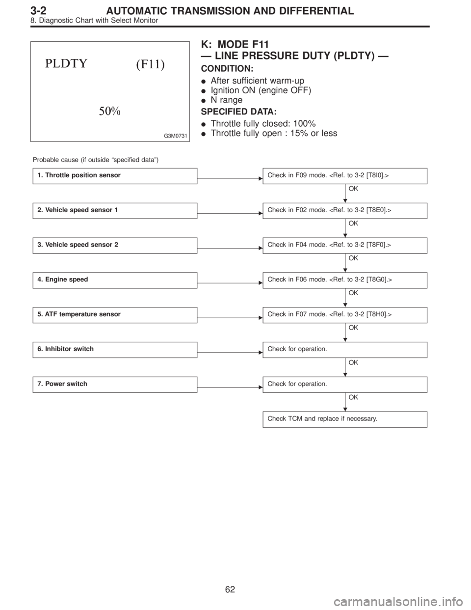
G3M0731
K: MODE F11
—LINE PRESSURE DUTY (PLDTY)—
CONDITION:
�After sufficient warm-up
�Ignition ON (engine OFF)
�N range
SPECIFIED DATA:
�Throttle fully closed: 100%
�Throttle fully open : 15% or less
Probable cause (if outside“specified data”)
1. Throttle position sensor
�Check in F09 mode.
OK
2. Vehicle speed sensor 1
�Check in F02 mode.
OK
3. Vehicle speed sensor 2
�Check in F04 mode.
OK
4. Engine speed
�Check in F06 mode.
OK
5. ATF temperature sensor
�Check in F07 mode.
OK
6. Inhibitor switch
�Check for operation.
OK
7. Power switch
�Check for operation.
OK
Check TCM and replace if necessary.
�
�
�
�
�
�
�
62
3-2AUTOMATIC TRANSMISSION AND DIFFERENTIAL
8. Diagnostic Chart with Select Monitor
Page 1618 of 2248
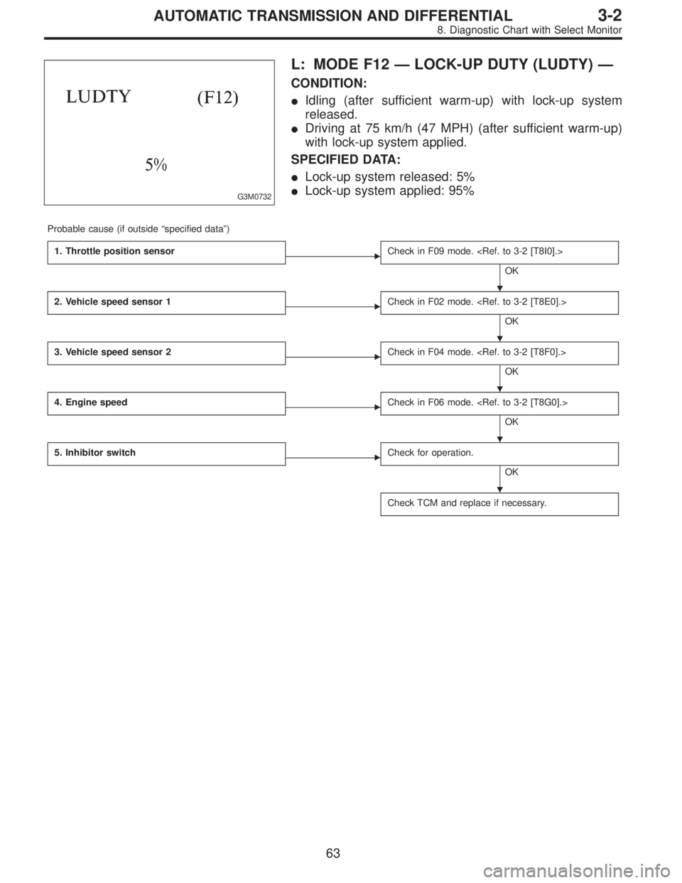
G3M0732
L: MODE F12—LOCK-UP DUTY (LUDTY)—
CONDITION:
�Idling (after sufficient warm-up) with lock-up system
released.
�Driving at 75 km/h (47 MPH) (after sufficient warm-up)
with lock-up system applied.
SPECIFIED DATA:
�Lock-up system released: 5%
�Lock-up system applied: 95%
Probable cause (if outside“specified data”)
1. Throttle position sensor
�Check in F09 mode.
OK
2. Vehicle speed sensor 1
�Check in F02 mode.
OK
3. Vehicle speed sensor 2
�Check in F04 mode.
OK
4. Engine speed
�Check in F06 mode.
OK
5. Inhibitor switch
�Check for operation.
OK
Check TCM and replace if necessary.
�
�
�
�
�
63
3-2AUTOMATIC TRANSMISSION AND DIFFERENTIAL
8. Diagnostic Chart with Select Monitor
Page 1619 of 2248
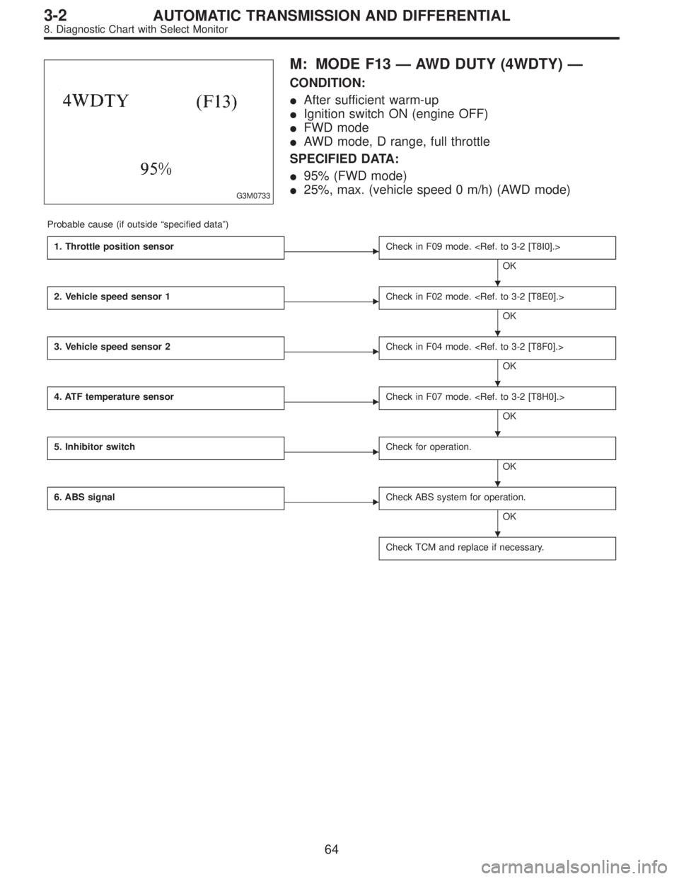
G3M0733
M: MODE F13—AWD DUTY (4WDTY)—
CONDITION:
�After sufficient warm-up
�Ignition switch ON (engine OFF)
�FWD mode
�AWD mode, D range, full throttle
SPECIFIED DATA:
�95% (FWD mode)
�25%, max. (vehicle speed 0 m/h) (AWD mode)
Probable cause (if outside“specified data”)
1. Throttle position sensor
�Check in F09 mode.
OK
2. Vehicle speed sensor 1
�Check in F02 mode.
OK
3. Vehicle speed sensor 2
�Check in F04 mode.
OK
4. ATF temperature sensor
�Check in F07 mode.
OK
5. Inhibitor switch
�Check for operation.
OK
6. ABS signal
�Check ABS system for operation.
OK
Check TCM and replace if necessary.
�
�
�
�
�
�
64
3-2AUTOMATIC TRANSMISSION AND DIFFERENTIAL
8. Diagnostic Chart with Select Monitor
Page 1624 of 2248

9. General Diagnostic Table
Problem parts
Inhibitor switch
Control module
Vehicle speed sensor 1
Vehicle speed sensor 2
Select cable
Select lever
FWD switch
Starter motor and harness
Throttle position sensor
Diagnosis switch
Accumulator (“N”—“D”)
Accumulator (2A)
Accumulator (4A)
Accumulator (3R)
ATF temperature sensor
Strainer
Duty solenoid A
Duty solenoid B
Shift solenoid 1
Shift solenoid 2
Shift solenoid 3
Control valve
Detent spring
Manual plate
Transfer clutch
Transfer valve
Transfer pipe
Duty solenoid C
Forward clutch
Symptom1234567891011121314151617181920212223242526272829
Starter does not rotate when select lever is
in“P”or“N.”; starter rotates when select
lever is“R”,“D”,“3”or“2.”XXXX
Abnormal noise when select lever is in“P”or
“N.”XX
Hissing noise occurs during standing starts. X
Noise occurs while driving in“D
1”range.
Noise occurs while driving in“D
2”range.
Noise occurs while driving in“D
3”range.
Noise occurs while driving in“D
4”range.
Engine stalls while shifting from one range to
another.X
Vehicle moves when select lever is in“N.”X
Shock occurs when select lever is moved
from“N”to“D.”XX X
Excessive time lag occurs when select lever
is moved from“N”to“D.”XX
Shock occurs when select lever is moved
from“N”to“R.”XXX
Excessive time lag occurs when select lever
is moved from“N”to“R.”X
Vehicle does not start in any shift range
(engine revving up).XX
Vehicle does not start in any shift range
(engine stall).
Vehicle does not start in“R”range only
(engine revving up).XX X
Vehicle does not start in“R”range only
(engine stall).X
Vehicle does not start in“D”or“3”range
(engine revving up).X
Vehicle does not start in“D”,“3”or“2”range
(engine revving up).X
Vehicle does not start in“D”,“3”or“2”range
(engine stall).
Vehicle starts in“R”range only (engine rev-
ving up).X
Acceleration during standing starts is poor
(high stall rpm).XX
Acceleration during standing starts is poor
(low stall rpm).
Acceleration is poor when select lever is in
“D”,“3”or“2”range (normal stall rpm).XX
Acceleration is poor when select lever is in
“R”(normal stall rpm).X
No shift occurs from 1st to 2nd gear. X X X X X X X
No shift occurs from 2nd to 3rd gear. XX
No shift occurs from 3rd to 4th gear. X X X X X
No“kick-down”shifts occur. X X
Engine brake is not effected when select
lever is in“3”range.XX X X
1234567891011121314151617181920212223242526272829
69
3-2AUTOMATIC TRANSMISSION AND DIFFERENTIAL
9. General Diagnostic Table
—
F03 = vehicle speed (VSP1):
to be indicated in“km/h”.
CONDITION:
Raise vehicle off ground and operate at constant speed.
SPECIFIED DATA:
Com")