Page 146 of 2248
B2M0375A
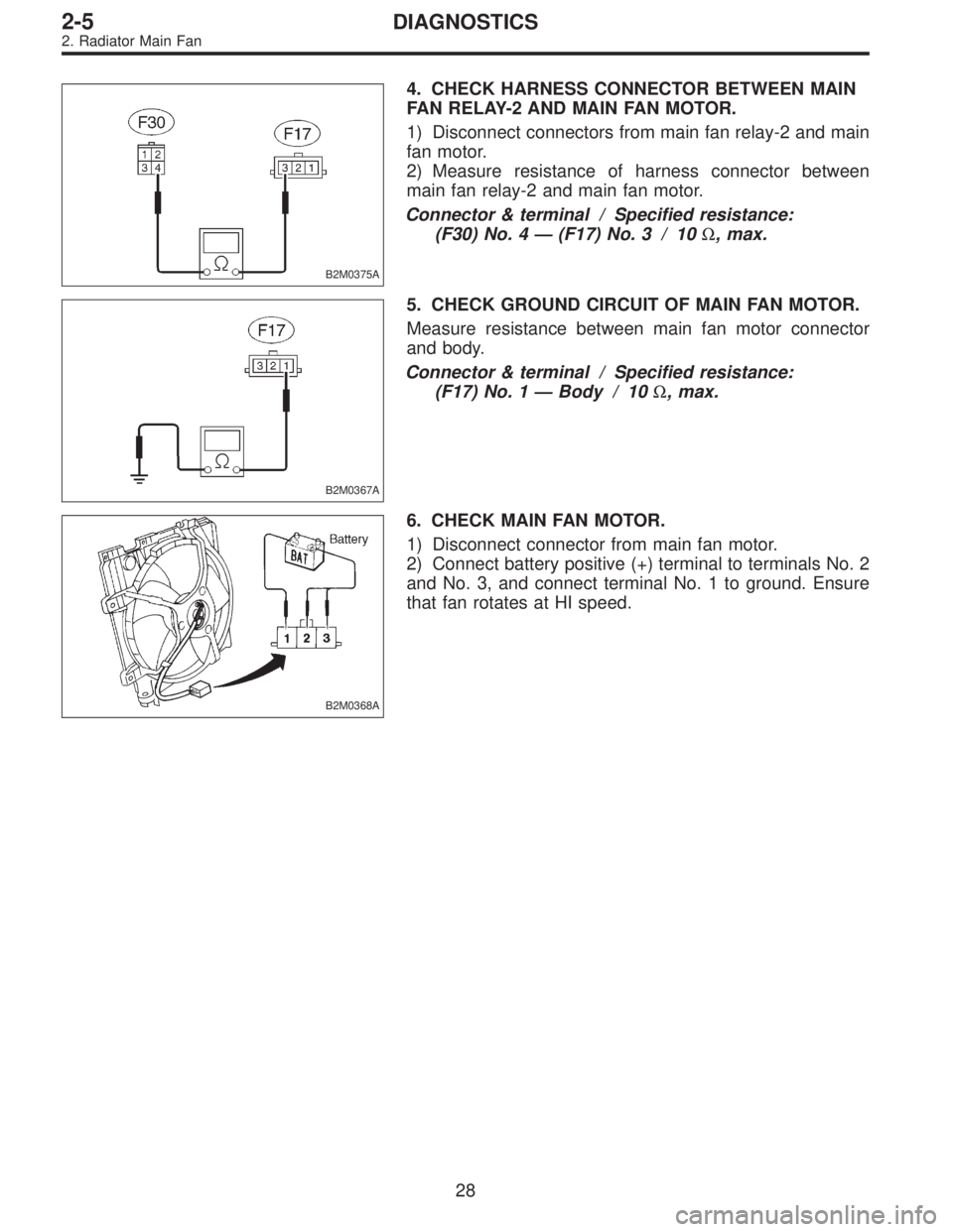
4. CHECK HARNESS CONNECTOR BETWEEN MAIN
FAN RELAY-2 AND MAIN FAN MOTOR.
1) Disconnect connectors from main fan relay-2 and main
fan motor.
2) Measure resistance of harness connector between
main fan relay-2 and main fan motor.
Connector & terminal / Specified resistance:
(F30) No. 4—(F17) No. 3 / 10Ω, max.
B2M0367A
5. CHECK GROUND CIRCUIT OF MAIN FAN MOTOR.
Measure resistance between main fan motor connector
and body.
Connector & terminal / Specified resistance:
(F17) No. 1—Body / 10Ω, max.
B2M0368A
6. CHECK MAIN FAN MOTOR.
1) Disconnect connector from main fan motor.
2) Connect battery positive (+) terminal to terminals No. 2
and No. 3, and connect terminal No. 1 to ground. Ensure
that fan rotates at HI speed.
28
2-5DIAGNOSTICS
2. Radiator Main Fan
Page 149 of 2248
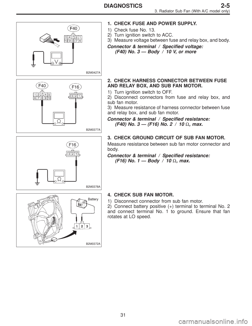
B2M0427A
1. CHECK FUSE AND POWER SUPPLY.
1) Check fuse No. 13.
2) Turn ignition switch to ACC.
3) Measure voltage between fuse and relay box, and body.
Connector & terminal / Specified voltage:
(F40) No. 3—Body / 10 V, or more
B2M0377A
2. CHECK HARNESS CONNECTOR BETWEEN FUSE
AND RELAY BOX, AND SUB FAN MOTOR.
1) Turn ignition switch to OFF.
2) Disconnect connectors from fuse and relay box, and
sub fan motor.
3) Measure resistance of harness connector between fuse
and relay box, and sub fan motor.
Connector & terminal / Specified resistance:
(F40) No. 3—(F16) No. 2 / 10Ω, max.
B2M0378A
3. CHECK GROUND CIRCUIT OF SUB FAN MOTOR.
Measure resistance between sub fan motor connector and
body.
Connector & terminal / Specified resistance:
(F16) No. 1—Body / 10Ω, max.
B2M0372A
4. CHECK SUB FAN MOTOR.
1) Disconnect connector from sub fan motor.
2) Connect battery positive (+) terminal to terminal No. 2
and connect terminal No. 1 to ground. Ensure that fan
rotates at LO speed.
31
2-5DIAGNOSTICS
3. Radiator Sub Fan (With A/C model only)
Page 151 of 2248
![SUBARU LEGACY 1995 Service Repair Manual 1. CHECK OPERATION OF SUB FAN MOTOR LO
MODE.
Check that radiator sub fan rotates at LO speed under each
condition described under LO mode operation. <Ref. to 2-5
[K3A0].>
B2M0379A
2. CHECK POWER SUPPL](/manual-img/17/57432/w960_57432-150.png "SUBARU LEGACY 1995 Service Repair Manual 1. CHECK OPERATION OF SUB FAN MOTOR LO
MODE.
Check that radiator sub fan rotates at LO speed under each
condition described under LO mode operation. <Ref. to 2-5
[K3A0].>
B2M0379A
2. CHECK POWER SUPPL")
1. CHECK OPERATION OF SUB FAN MOTOR LO
MODE.
Check that radiator sub fan rotates at LO speed under each
condition described under LO mode operation.
[K3A0].>
B2M0379A
2. CHECK POWER SUPPLY TO SUB FAN RELAY-2.
1) Turn ignition switch to OFF.
2) Disconnect connector from A/C relay holder.
3) Measure voltage between A/C relay holder connector
and body.
Connector & terminal / Specified voltage:
(F29) No. 1—Body / 1 V, max.
(F29) No. 2—Body / 1 V, max.
4) Turn ignition switch to ON.
5) Measure voltage between A/C relay holder connector
and body.
Connector & terminal / Specified voltage:
(F29) No. 1—Body / 10 V, or more
(F29) No. 2—Body / 10 V, or more
B2M0370A
3. CHECK SUB FAN RELAY-2.
1) Turn ignition switch to OFF.
2) Remove sub fan relay-2 from A/C relay holder.
3) Check continuity between terminals (indicated in table
below) when terminal (1) is connected to battery and ter-
minal (3) is grounded.
When current flows.Between terminals (2)
and (4)Continuity exists.
When current does not
flow.Between terminals (2)
and (4)Continuity does not
exist.
Between terminals (1)
and (3)Continuity exists.
33
2-5DIAGNOSTICS
3. Radiator Sub Fan (With A/C model only)
Page 152 of 2248
B2M0397A
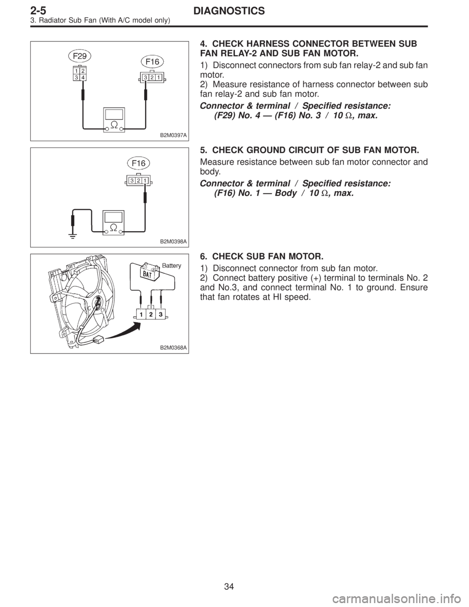
4. CHECK HARNESS CONNECTOR BETWEEN SUB
FAN RELAY-2 AND SUB FAN MOTOR.
1) Disconnect connectors from sub fan relay-2 and sub fan
motor.
2) Measure resistance of harness connector between sub
fan relay-2 and sub fan motor.
Connector & terminal / Specified resistance:
(F29) No. 4—(F16) No. 3 / 10Ω, max.
B2M0398A
5. CHECK GROUND CIRCUIT OF SUB FAN MOTOR.
Measure resistance between sub fan motor connector and
body.
Connector & terminal / Specified resistance:
(F16) No. 1—Body / 10Ω, max.
B2M0368A
6. CHECK SUB FAN MOTOR.
1) Disconnect connector from sub fan motor.
2) Connect battery positive (+) terminal to terminals No. 2
and No.3, and connect terminal No. 1 to ground. Ensure
that fan rotates at HI speed.
34
2-5DIAGNOSTICS
3. Radiator Sub Fan (With A/C model only)
Page 180 of 2248
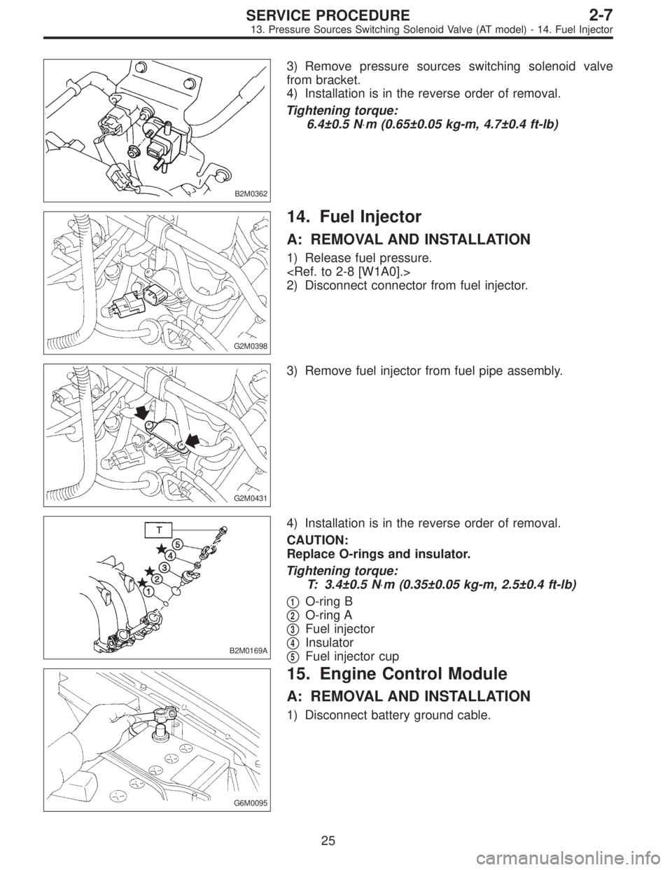
B2M0362
3) Remove pressure sources switching solenoid valve
from bracket.
4) Installation is in the reverse order of removal.
Tightening torque:
6.4±0.5 N⋅m (0.65±0.05 kg-m, 4.7±0.4 ft-lb)
G2M0398
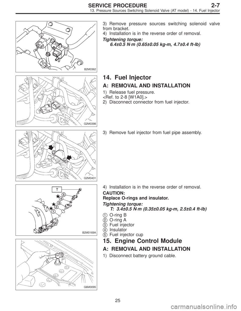
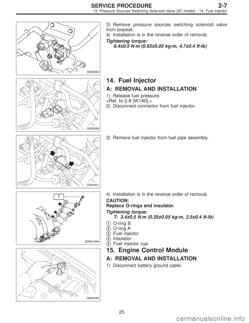
14. Fuel Injector
A: REMOVAL AND INSTALLATION
1) Release fuel pressure.
2) Disconnect connector from fuel injector.
G2M0431
3) Remove fuel injector from fuel pipe assembly.
B2M0169A
4) Installation is in the reverse order of removal.
CAUTION:
Replace O-rings and insulator.
Tightening torque:
T: 3.4±0.5 N⋅m (0.35±0.05 kg-m, 2.5±0.4 ft-lb)
�
1O-ring B
�
2O-ring A
�
3Fuel injector
�
4Insulator
�
5Fuel injector cup
G6M0095
15. Engine Control Module
A: REMOVAL AND INSTALLATION
1) Disconnect battery ground cable.
25
2-7SERVICE PROCEDURE
13. Pressure Sources Switching Solenoid Valve (AT model) - 14. Fuel Injector
Page 181 of 2248
B2M0362
3) Remove pressure sources switching solenoid valve
from bracket.
4) Installation is in the reverse order of removal.
Tightening torque:
6.4±0.5 N⋅m (0.65±0.05 kg-m, 4.7±0.4 ft-lb)
G2M0398
14. Fuel Injector
A: REMOVAL AND INSTALLATION
1) Release fuel pressure.
2) Disconnect connector from fuel injector.
G2M0431
3) Remove fuel injector from fuel pipe assembly.
B2M0169A
4) Installation is in the reverse order of removal.
CAUTION:
Replace O-rings and insulator.
Tightening torque:
T: 3.4±0.5 N⋅m (0.35±0.05 kg-m, 2.5±0.4 ft-lb)
�
1O-ring B
�
2O-ring A
�
3Fuel injector
�
4Insulator
�
5Fuel injector cup
G6M0095
15. Engine Control Module
A: REMOVAL AND INSTALLATION
1) Disconnect battery ground cable.
25
2-7SERVICE PROCEDURE
13. Pressure Sources Switching Solenoid Valve (AT model) - 14. Fuel Injector
Page 182 of 2248
B2M0362
3) Remove pressure sources switching solenoid valve
from bracket.
4) Installation is in the reverse order of removal.
Tightening torque:
6.4±0.5 N⋅m (0.65±0.05 kg-m, 4.7±0.4 ft-lb)
G2M0398
14. Fuel Injector
A: REMOVAL AND INSTALLATION
1) Release fuel pressure.
2) Disconnect connector from fuel injector.
G2M0431
3) Remove fuel injector from fuel pipe assembly.
B2M0169A
4) Installation is in the reverse order of removal.
CAUTION:
Replace O-rings and insulator.
Tightening torque:
T: 3.4±0.5 N⋅m (0.35±0.05 kg-m, 2.5±0.4 ft-lb)
�
1O-ring B
�
2O-ring A
�
3Fuel injector
�
4Insulator
�
5Fuel injector cup
G6M0095
15. Engine Control Module
A: REMOVAL AND INSTALLATION
1) Disconnect battery ground cable.
25
2-7SERVICE PROCEDURE
13. Pressure Sources Switching Solenoid Valve (AT model) - 14. Fuel Injector
Page 184 of 2248
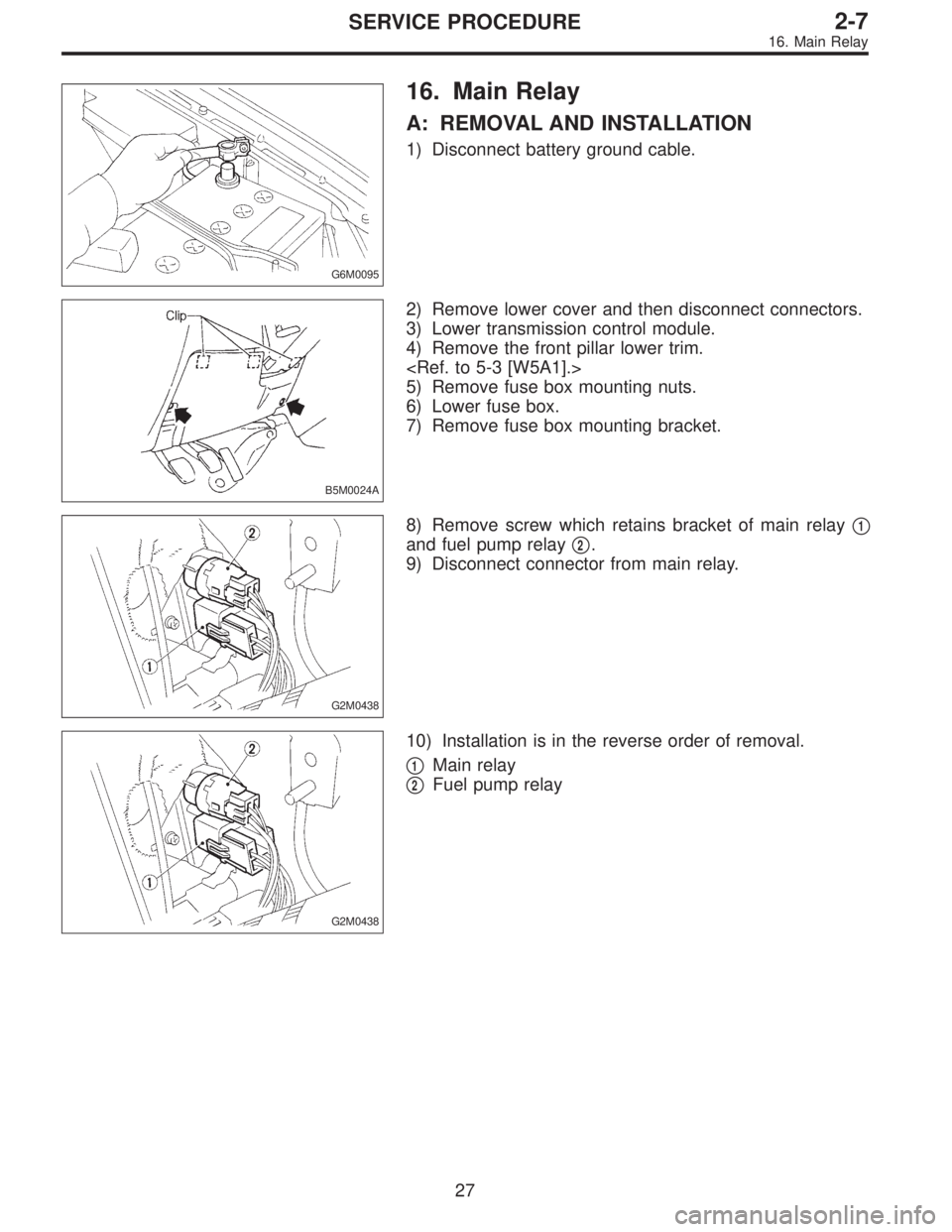
G6M0095
16. Main Relay
A: REMOVAL AND INSTALLATION
1) Disconnect battery ground cable.
B5M0024A
2) Remove lower cover and then disconnect connectors.
3) Lower transmission control module.
4) Remove the front pillar lower trim.
5) Remove fuse box mounting nuts.
6) Lower fuse box.
7) Remove fuse box mounting bracket.
G2M0438
8) Remove screw which retains bracket of main relay�1
and fuel pump relay�2.
9) Disconnect connector from main relay.
G2M0438
10) Installation is in the reverse order of removal.
�
1Main relay
�
2Fuel pump relay
27
2-7SERVICE PROCEDURE
16. Main Relay