Page 252 of 2248
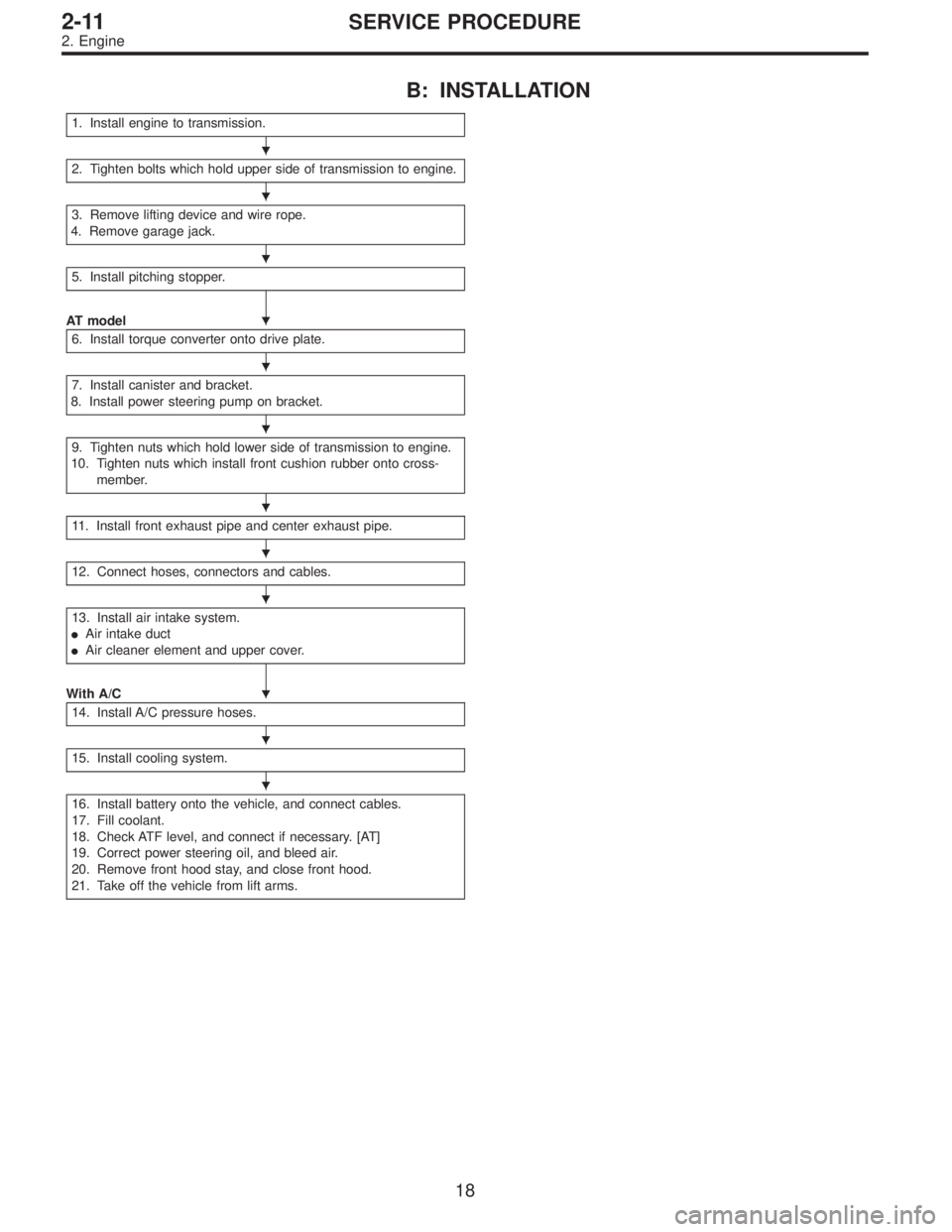
B: INSTALLATION
1. Install engine to transmission.
2. Tighten bolts which hold upper side of transmission to engine.
3. Remove lifting device and wire rope.
4. Remove garage jack.
5. Install pitching stopper.
AT model
6. Install torque converter onto drive plate.
7. Install canister and bracket.
8. Install power steering pump on bracket.
9. Tighten nuts which hold lower side of transmission to engine.
10. Tighten nuts which install front cushion rubber onto cross-
member.
11. Install front exhaust pipe and center exhaust pipe.
12. Connect hoses, connectors and cables.
13. Install air intake system.
�Air intake duct
�Air cleaner element and upper cover.
With A/C
14. Install A/C pressure hoses.
15. Install cooling system.
16. Install battery onto the vehicle, and connect cables.
17. Fill coolant.
18. Check ATF level, and connect if necessary. [AT]
19. Correct power steering oil, and bleed air.
20. Remove front hood stay, and close front hood.
21. Take off the vehicle from lift arms.
�
�
�
�
�
�
�
�
�
�
�
�
18
2-11SERVICE PROCEDURE
2. Engine
Page 258 of 2248
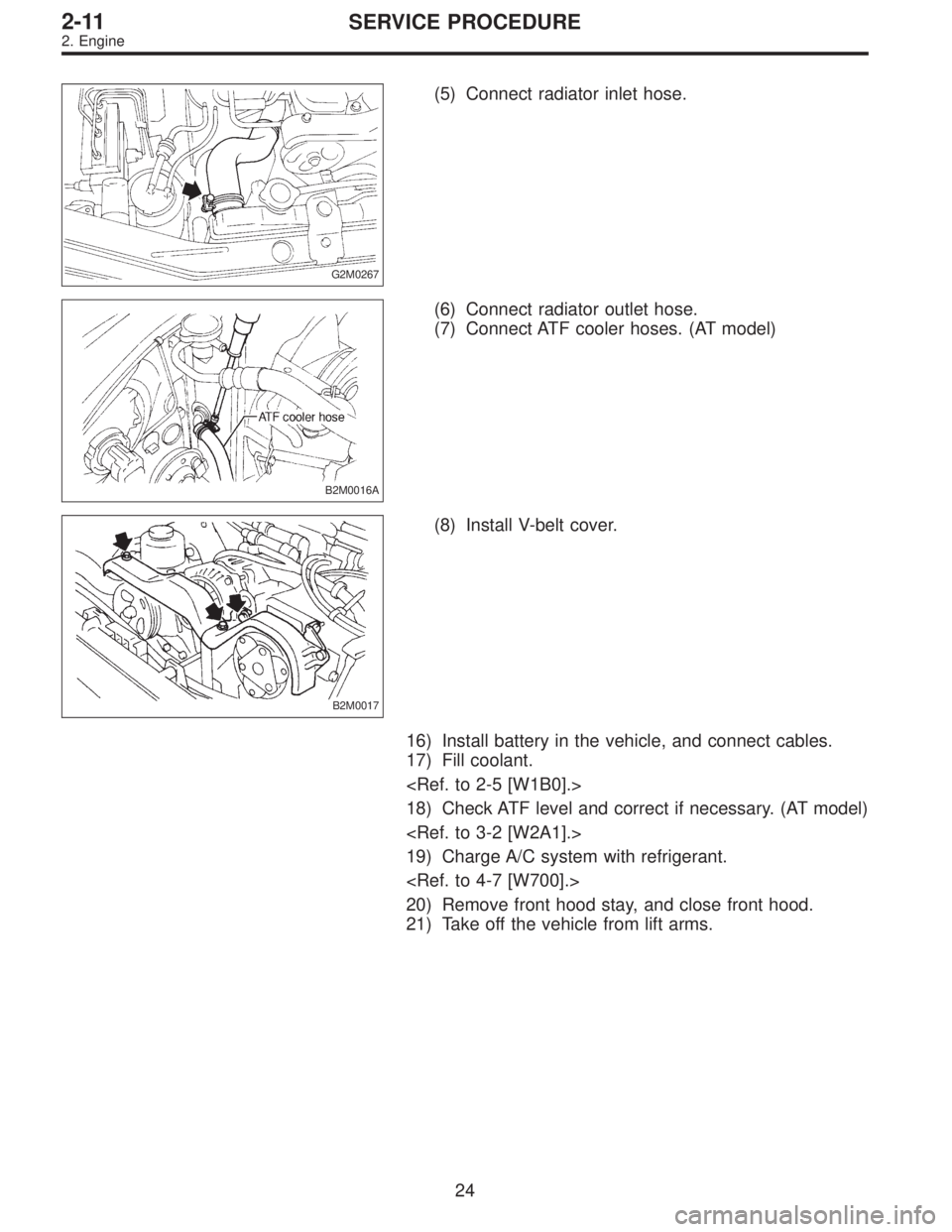
G2M0267
(5) Connect radiator inlet hose.
B2M0016A
(6) Connect radiator outlet hose.
(7) Connect ATF cooler hoses. (AT model)
B2M0017
(8) Install V-belt cover.
16) Install battery in the vehicle, and connect cables.
17) Fill coolant.
18) Check ATF level and correct if necessary. (AT model)
19) Charge A/C system with refrigerant.
20) Remove front hood stay, and close front hood.
21) Take off the vehicle from lift arms.
24
2-11SERVICE PROCEDURE
2. Engine
Page 259 of 2248
3. Transmission
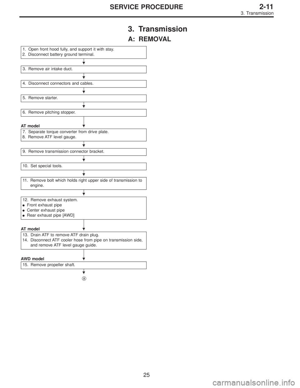
A: REMOVAL
1. Open front hood fully, and support it with stay.
2. Disconnect battery ground terminal.
3. Remove air intake duct.
4. Disconnect connectors and cables.
5. Remove starter.
6. Remove pitching stopper.
AT model
7. Separate torque converter from drive plate.
8. Remove ATF level gauge.
9. Remove transmission connector bracket.
10. Set special tools.
11. Remove bolt which holds right upper side of transmission to
engine.
12. Remove exhaust system.
�Front exhaust pipe
�Center exhaust pipe
�Rear exhaust pipe [AWD]
AT model
13. Drain ATF to remove ATF drain plug.
14. Disconnect ATF cooler hose from pipe on transmission side,
and remove ATF level gauge guide.
AWD model
15. Remove propeller shaft.
�A
�
�
�
�
�
�
�
�
�
�
�
�
25
2-11SERVICE PROCEDURE
3. Transmission
Page 261 of 2248
G2M0266
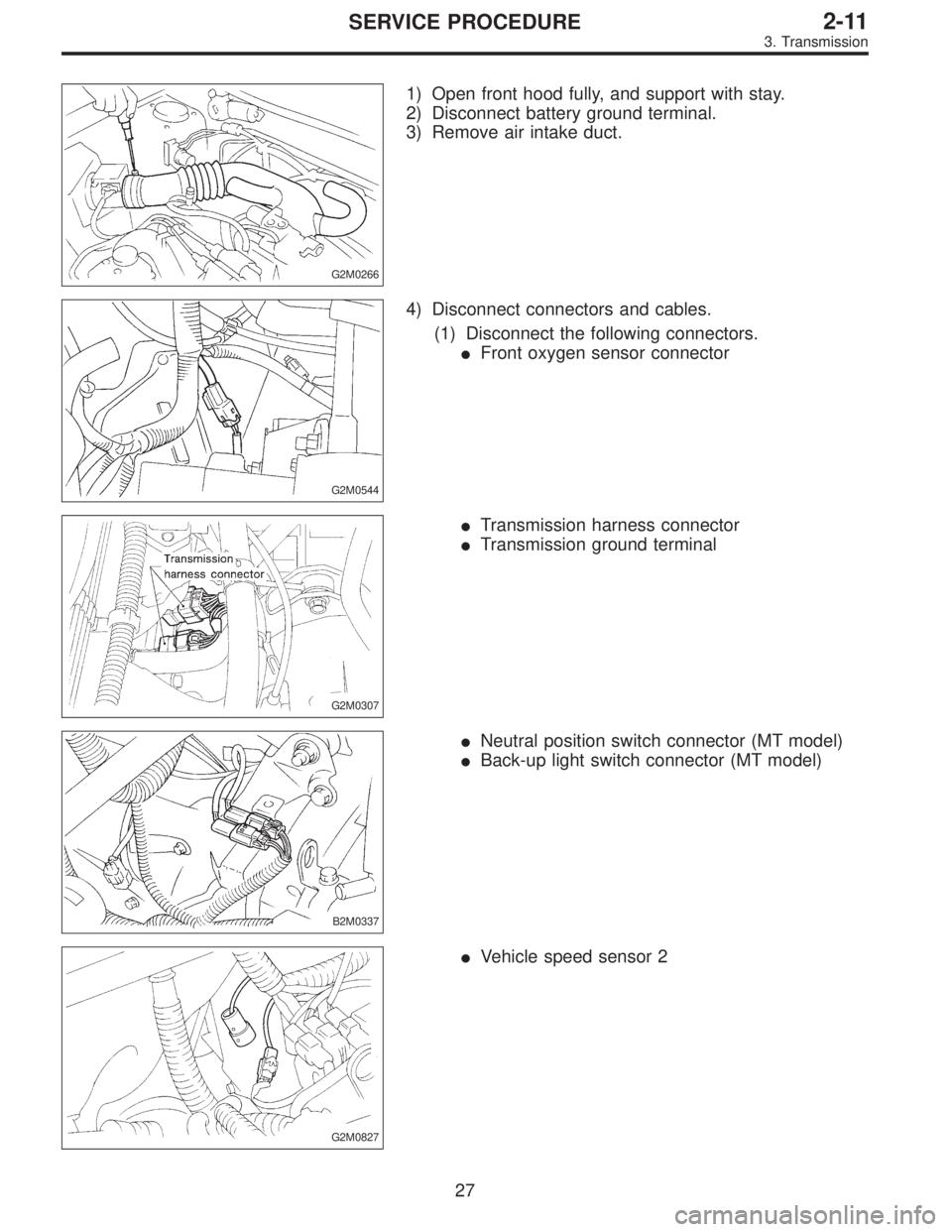
1) Open front hood fully, and support with stay.
2) Disconnect battery ground terminal.
3) Remove air intake duct.
G2M0544
4) Disconnect connectors and cables.
(1) Disconnect the following connectors.
�Front oxygen sensor connector
G2M0307
�Transmission harness connector
�Transmission ground terminal
B2M0337
�Neutral position switch connector (MT model)
�Back-up light switch connector (MT model)
G2M0827
�Vehicle speed sensor 2
27
2-11SERVICE PROCEDURE
3. Transmission
Page 269 of 2248
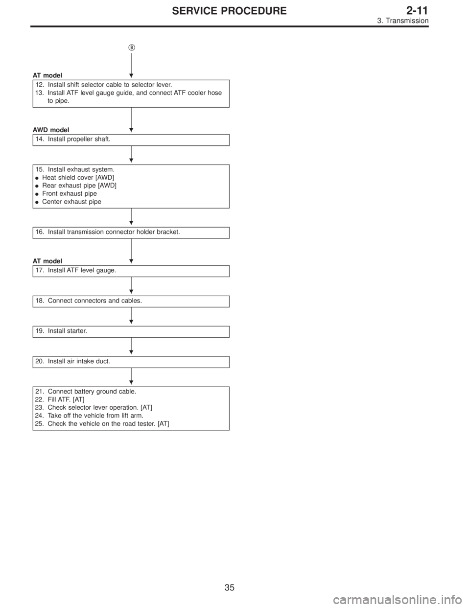
�B
AT model
12. Install shift selector cable to selector lever.
13. Install ATF level gauge guide, and connect ATF cooler hose
to pipe.
AWD model
14. Install propeller shaft.
15. Install exhaust system.
�Heat shield cover [AWD]
�Rear exhaust pipe [AWD]
�Front exhaust pipe
�Center exhaust pipe
16. Install transmission connector holder bracket.
AT model
17. Install ATF level gauge.
18. Connect connectors and cables.
19. Install starter.
20. Install air intake duct.
21. Connect battery ground cable.
22. Fill ATF. [AT]
23. Check selector lever operation. [AT]
24. Take off the vehicle from lift arm.
25. Check the vehicle on the road tester. [AT]
�
�
�
�
�
�
�
�
�
35
2-11SERVICE PROCEDURE
3. Transmission
Page 276 of 2248
G2M0266
20) Install air intake duct.
21) Connect battery ground cable.
22) Fill ATF. (AT model)
23) Check selector lever operation. (AT model)
24) Take off vehicle from lift arms.
25) Check the vehicle on road tester. (AT model)
42
2-11SERVICE PROCEDURE
3. Transmission
Page 461 of 2248
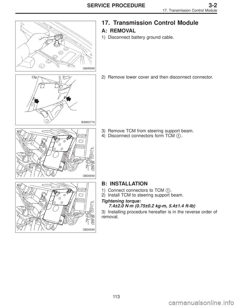
G6M0095
17. Transmission Control Module
A: REMOVAL
1) Disconnect battery ground cable.
B3M0377A
2) Remove lower cover and then disconnect connector.
OBD0040
3) Remove TCM from steering support beam.
4) Disconnect connectors form TCM�
1.
OBD0040
B: INSTALLATION
1) Connect connectors to TCM�1.
2) Install TCM to steering support beam.
Tightening torque:
7.4±2.0 N⋅m (0.75±0.2 kg-m, 5.4±1.4 ft-lb)
3) Installing procedure hereafter is in the reverse order of
removal.
11 3
3-2SERVICE PROCEDURE
17. Transmission Control Module
Page 485 of 2248
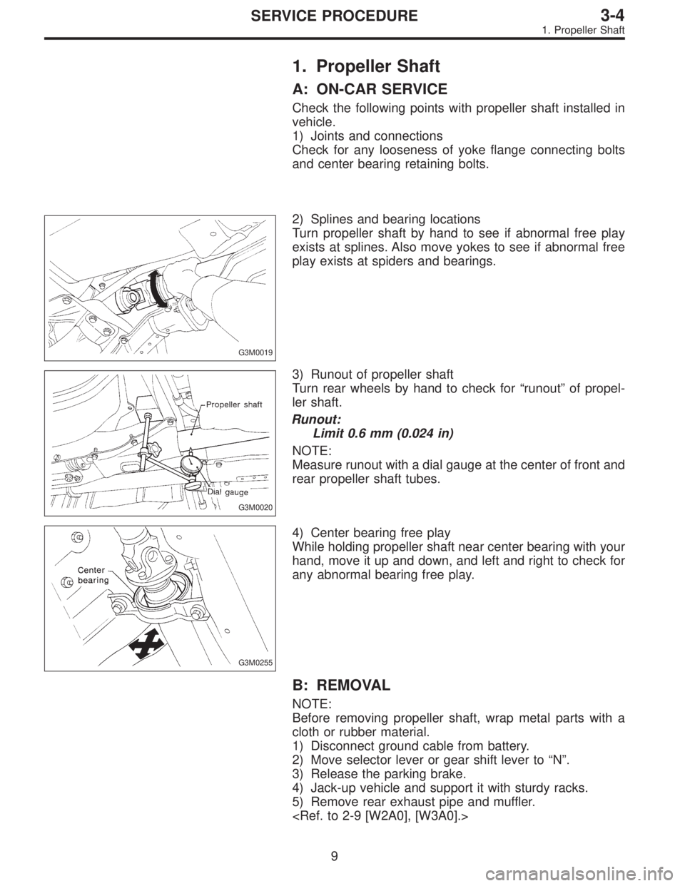
1. Propeller Shaft
A: ON-CAR SERVICE
Check the following points with propeller shaft installed in
vehicle.
1) Joints and connections
Check for any looseness of yoke flange connecting bolts
and center bearing retaining bolts.
G3M0019
2) Splines and bearing locations
Turn propeller shaft by hand to see if abnormal free play
exists at splines. Also move yokes to see if abnormal free
play exists at spiders and bearings.
G3M0020
3) Runout of propeller shaft
Turn rear wheels by hand to check for“runout”of propel-
ler shaft.
Runout:
Limit 0.6 mm (0.024 in)
NOTE:
Measure runout with a dial gauge at the center of front and
rear propeller shaft tubes.
G3M0255
4) Center bearing free play
While holding propeller shaft near center bearing with your
hand, move it up and down, and left and right to check for
any abnormal bearing free play.
B: REMOVAL
NOTE:
Before removing propeller shaft, wrap metal parts with a
cloth or rubber material.
1) Disconnect ground cable from battery.
2) Move selector lever or gear shift lever to“N”.
3) Release the parking brake.
4) Jack-up vehicle and support it with sturdy racks.
5) Remove rear exhaust pipe and muffler.
9
3-4SERVICE PROCEDURE
1. Propeller Shaft
![SUBARU LEGACY 1995 Service Repair Manual G2M0266
20) Install air intake duct.
21) Connect battery ground cable.
22) Fill ATF. (AT model)
<Ref. to 3-2 [W2A1].>
23) Check selector lever operation. (AT model)
<Ref. to 3-3 [W2E0].>
24) Take off](/manual-img/17/57432/w960_57432-275.png "SUBARU LEGACY 1995 Service Repair Manual G2M0266
20) Install air intake duct.
21) Connect battery ground cable.
22) Fill ATF. (AT model)
<Ref. to 3-2 [W2A1].>
23) Check selector lever operation. (AT model)
<Ref. to 3-3 [W2E0].>
24) Take off")