Page 490 of 2248
2. Rear Differential
A: ON-CAR SERVICE
1. FRONT OIL SEAL
1) Disconnect ground cable from battery.
2) Move selector lever or gear shift lever to“N”.
3) Release the parking brake.
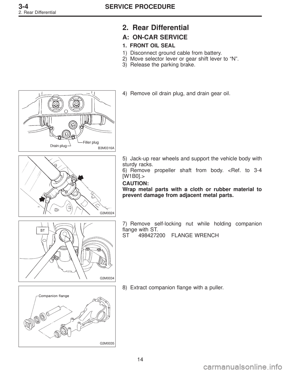
B3M0316A
4) Remove oil drain plug, and drain gear oil.
G3M0024
5) Jack-up rear wheels and support the vehicle body with
sturdy racks.
6) Remove propeller shaft from body.
[W1B0].>
CAUTION:
Wrap metal parts with a cloth or rubber material to
prevent damage from adjacent metal parts.
G3M0034
7) Remove self-locking nut while holding companion
flange with ST.
ST 498427200 FLANGE WRENCH
G3M0035
8) Extract companion flange with a puller.
14
3-4SERVICE PROCEDURE
2. Rear Differential
Page 492 of 2248
2. SIDE OIL SEAL
1) Disconnect ground cable from battery.
2) Move selector lever or gear shift lever to“N”.
3) Release the parking brake.
4) Loosen both wheel nuts.
5) Jack-up the vehicle and support it with rigid racks.
6) Remove wheels.
7) Remove rear exhaust pipe and muffler.
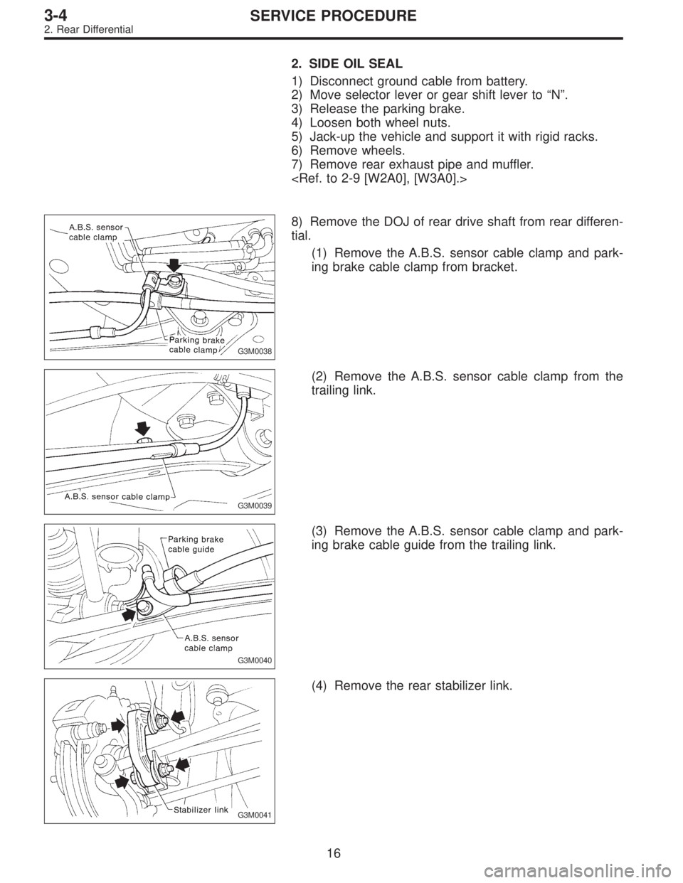
G3M0038
8) Remove the DOJ of rear drive shaft from rear differen-
tial.
(1) Remove the A.B.S. sensor cable clamp and park-
ing brake cable clamp from bracket.
G3M0039
(2) Remove the A.B.S. sensor cable clamp from the
trailing link.
G3M0040
(3) Remove the A.B.S. sensor cable clamp and park-
ing brake cable guide from the trailing link.
G3M0041
(4) Remove the rear stabilizer link.
16
3-4SERVICE PROCEDURE
2. Rear Differential
Page 495 of 2248
B: REMOVAL
1) Disconnect ground cable from battery.
2) Move selector lever or gear shift lever to“N”.
3) Release the parking brake.
4) Loosen wheel nuts.
5) Jack-up vehicle and support it with sturdy racks.
6) Remove wheels.
7) Remove rear exhaust pipe and muffler.
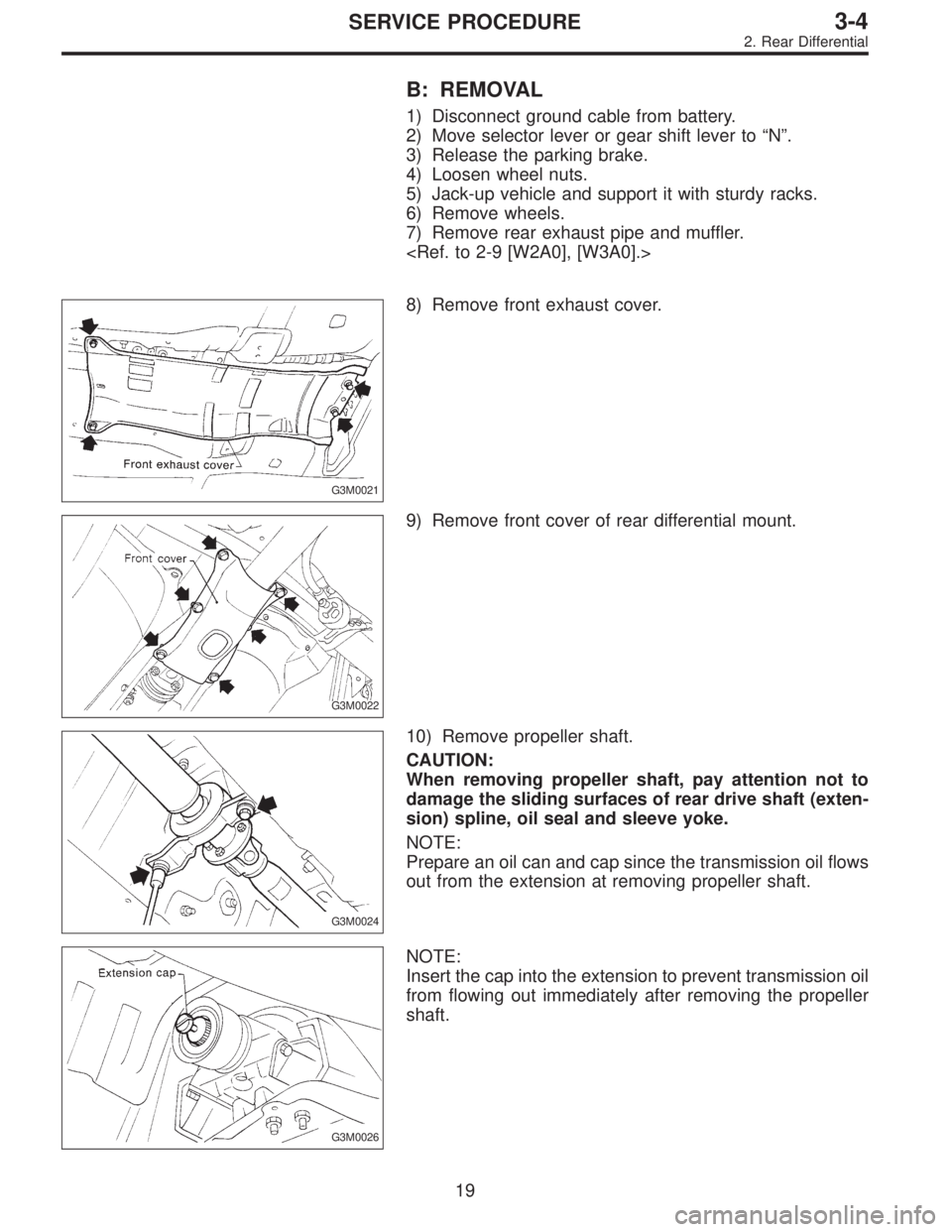
G3M0021
8) Remove front exhaust cover.
G3M0022
9) Remove front cover of rear differential mount.
G3M0024
10) Remove propeller shaft.
CAUTION:
When removing propeller shaft, pay attention not to
damage the sliding surfaces of rear drive shaft (exten-
sion) spline, oil seal and sleeve yoke.
NOTE:
Prepare an oil can and cap since the transmission oil flows
out from the extension at removing propeller shaft.
G3M0026
NOTE:
Insert the cap into the extension to prevent transmission oil
from flowing out immediately after removing the propeller
shaft.
19
3-4SERVICE PROCEDURE
2. Rear Differential
Page 514 of 2248
3. Rear Differential Front Member
A: REMOVAL
1) Disconnect ground cable from battery.
2) Move selector lever or gear shift lever to“N”.
3) Release the parking brake.
4) Loosen wheel nuts.
5) Jack-up vehicle and support it with sturdy racks.
6) Remove wheels.
7) Remove rear exhaust pipe and muffler.
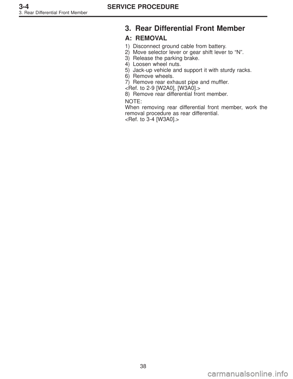
8) Remove rear differential front member.
NOTE:
When removing rear differential front member, work the
removal procedure as rear differential.
38
3-4SERVICE PROCEDURE
3. Rear Differential Front Member
Page 544 of 2248
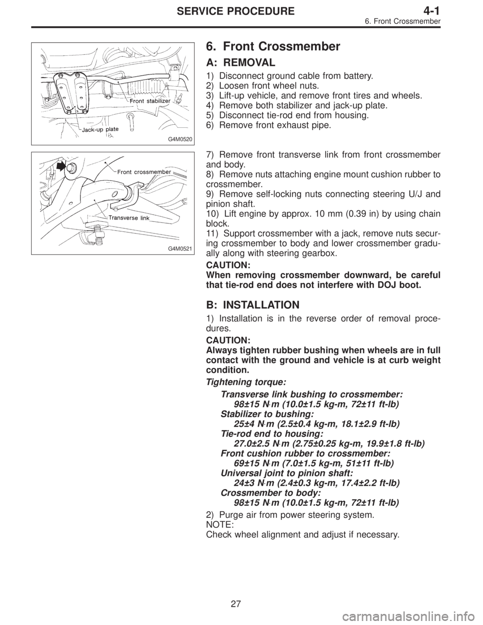
G4M0520
6. Front Crossmember
A: REMOVAL
1) Disconnect ground cable from battery.
2) Loosen front wheel nuts.
3) Lift-up vehicle, and remove front tires and wheels.
4) Remove both stabilizer and jack-up plate.
5) Disconnect tie-rod end from housing.
6) Remove front exhaust pipe.
G4M0521
7) Remove front transverse link from front crossmember
and body.
8) Remove nuts attaching engine mount cushion rubber to
crossmember.
9) Remove self-locking nuts connecting steering U/J and
pinion shaft.
10) Lift engine by approx. 10 mm (0.39 in) by using chain
block.
11) Support crossmember with a jack, remove nuts secur-
ing crossmember to body and lower crossmember gradu-
ally along with steering gearbox.
CAUTION:
When removing crossmember downward, be careful
that tie-rod end does not interfere with DOJ boot.
B: INSTALLATION
1) Installation is in the reverse order of removal proce-
dures.
CAUTION:
Always tighten rubber bushing when wheels are in full
contact with the ground and vehicle is at curb weight
condition.
Tightening torque:
Transverse link bushing to crossmember:
98±15 N⋅m (10.0±1.5 kg-m, 72±11 ft-lb)
Stabilizer to bushing:
25±4 N⋅m (2.5±0.4 kg-m, 18.1±2.9 ft-lb)
Tie-rod end to housing:
27.0±2.5 N⋅m (2.75±0.25 kg-m, 19.9±1.8 ft-lb)
Front cushion rubber to crossmember:
69±15 N⋅m (7.0±1.5 kg-m, 51±11 ft-lb)
Universal joint to pinion shaft:
24±3 N⋅m (2.4±0.3 kg-m, 17.4±2.2 ft-lb)
Crossmember to body:
98±15 N⋅m (10.0±1.5 kg-m, 72±11 ft-lb)
2) Purge air from power steering system.
NOTE:
Check wheel alignment and adjust if necessary.
27
4-1SERVICE PROCEDURE
6. Front Crossmember
Page 570 of 2248
1. Front Axle
A: REMOVAL
1) Disconnect ground cable from battery.
2) Jack-up vehicle, support it with safety stands, and
remove front wheels.
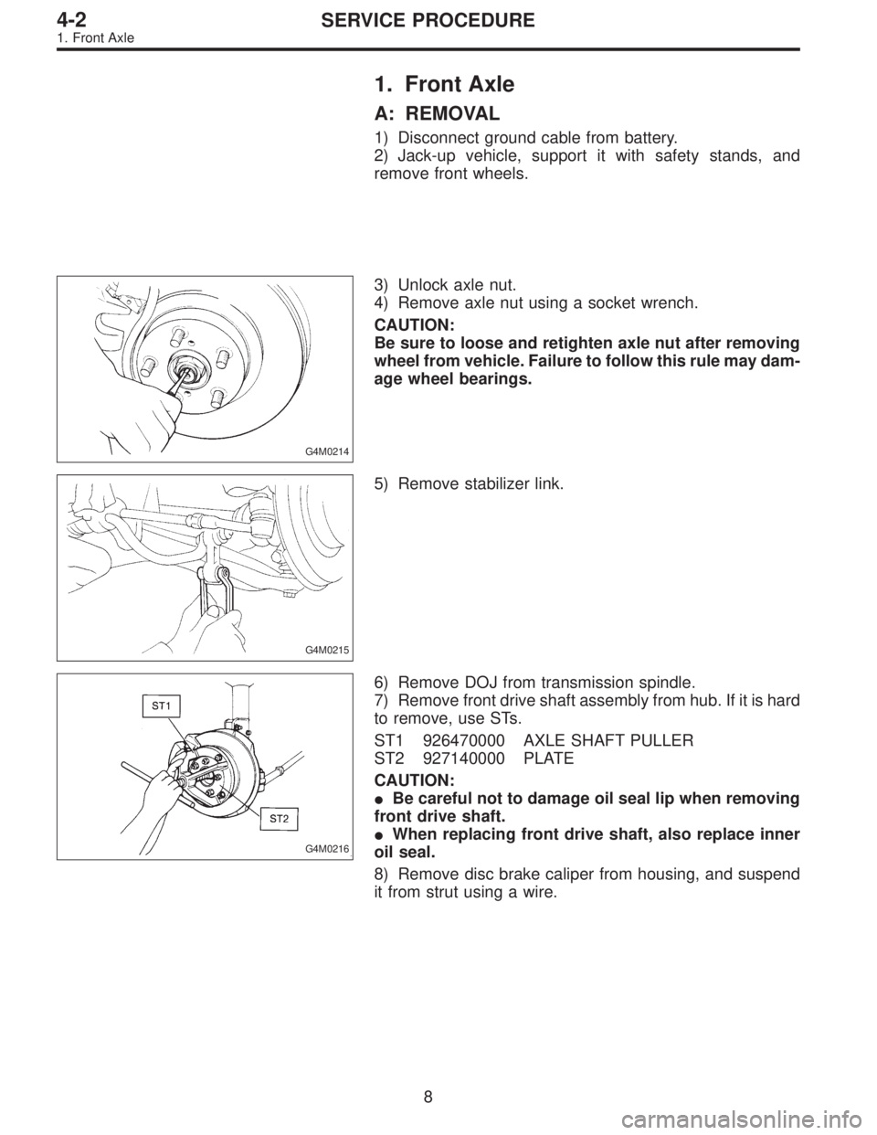
G4M0214
3) Unlock axle nut.
4) Remove axle nut using a socket wrench.
CAUTION:
Be sure to loose and retighten axle nut after removing
wheel from vehicle. Failure to follow this rule may dam-
age wheel bearings.
G4M0215
5) Remove stabilizer link.
G4M0216
6) Remove DOJ from transmission spindle.
7) Remove front drive shaft assembly from hub. If it is hard
to remove, use STs.
ST1 926470000 AXLE SHAFT PULLER
ST2 927140000 PLATE
CAUTION:
�Be careful not to damage oil seal lip when removing
front drive shaft.
�When replacing front drive shaft, also replace inner
oil seal.
8) Remove disc brake caliper from housing, and suspend
it from strut using a wire.
8
4-2SERVICE PROCEDURE
1. Front Axle
Page 577 of 2248
G4M0238
10) After tightening axle nut, lock it securely.
11) Install wheel and tighten wheel nuts to specified
torque.
Tightening torque:
88±10 N⋅m (9±1 kg-m, 65±7 ft-lb)
2. Rear Axle (AWD Model)
A: REMOVAL
1) Disconnect ground cable from battery.
2) Jack-up vehicle, and remove rear wheel cap and
wheels.
CAUTION:
Be sure to loosen and retighten axle nut after remov-
ing wheel from vehicle. Failure to follow this rule may
damage wheel bearings.
3) Unlock axle nut.
4) Remove axle nut using a socket wrench.
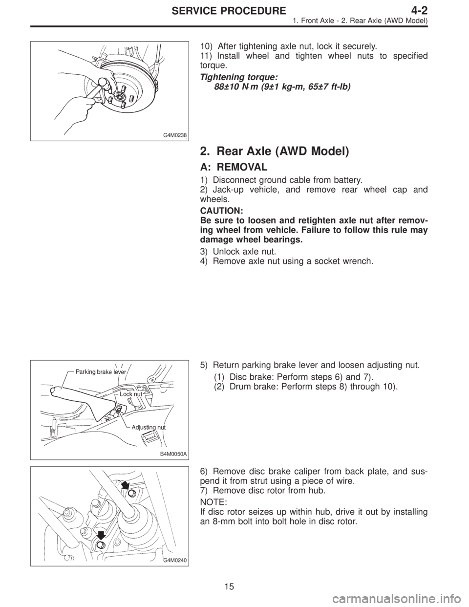
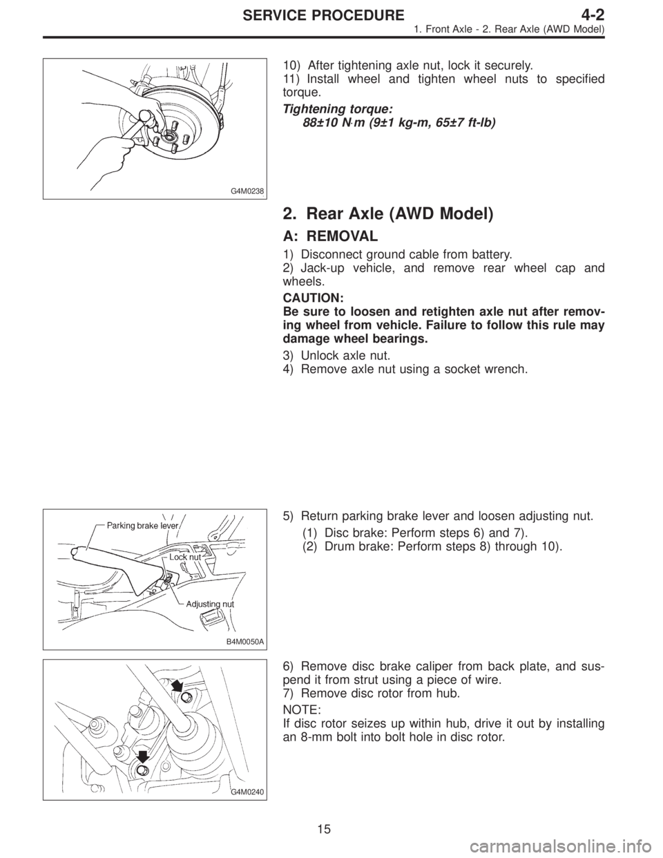
B4M0050A
5) Return parking brake lever and loosen adjusting nut.
(1) Disc brake: Perform steps 6) and 7).
(2) Drum brake: Perform steps 8) through 10).
G4M0240
6) Remove disc brake caliper from back plate, and sus-
pend it from strut using a piece of wire.
7) Remove disc rotor from hub.
NOTE:
If disc rotor seizes up within hub, drive it out by installing
an 8-mm bolt into bolt hole in disc rotor.
15
4-2SERVICE PROCEDURE
1. Front Axle - 2. Rear Axle (AWD Model)
Page 578 of 2248
G4M0238
10) After tightening axle nut, lock it securely.
11) Install wheel and tighten wheel nuts to specified
torque.
Tightening torque:
88±10 N⋅m (9±1 kg-m, 65±7 ft-lb)
2. Rear Axle (AWD Model)
A: REMOVAL
1) Disconnect ground cable from battery.
2) Jack-up vehicle, and remove rear wheel cap and
wheels.
CAUTION:
Be sure to loosen and retighten axle nut after remov-
ing wheel from vehicle. Failure to follow this rule may
damage wheel bearings.
3) Unlock axle nut.
4) Remove axle nut using a socket wrench.
B4M0050A
5) Return parking brake lever and loosen adjusting nut.
(1) Disc brake: Perform steps 6) and 7).
(2) Drum brake: Perform steps 8) through 10).
G4M0240
6) Remove disc brake caliper from back plate, and sus-
pend it from strut using a piece of wire.
7) Remove disc rotor from hub.
NOTE:
If disc rotor seizes up within hub, drive it out by installing
an 8-mm bolt into bolt hole in disc rotor.
15
4-2SERVICE PROCEDURE
1. Front Axle - 2. Rear Axle (AWD Model)