Page 1894 of 2248
2. Basic Diagnostics Procedures
The most important purpose of diagnostics is to determine
which part is malfunctioning quickly, to save time and labor.
A: IDENTIFICATION OF TROUBLE SYMPTOM
Determine what the problem is based on the symptom.
B: PROBABLE CAUSE OF TROUBLE
Look at the wiring diagram and check the system’s circuit.
Then check the switch, relay, fuse, ground, etc.
C: LOCATION AND REPAIR OF TROUBLE
1) Using the diagnostics narrow down the causes.
2) If necessary, use a voltmeter, ohmmeter, etc.
3) Before replacing certain component parts (switch, relay,
etc.), check the power supply, ground, for open wiring
harness, poor connectors, etc. If no problems are
encountered, check the component parts.
D: CONFIRMATION OF SYSTEM OPERATION
After repairing, ensure that the system operates properly.
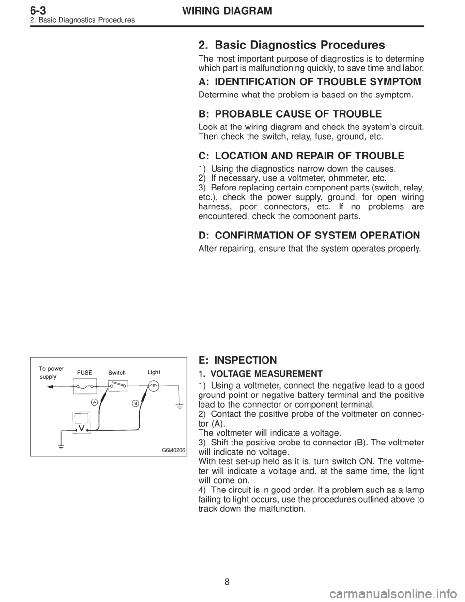
G6M0206
E: INSPECTION
1. VOLTAGE MEASUREMENT
1) Using a voltmeter, connect the negative lead to a good
ground point or negative battery terminal and the positive
lead to the connector or component terminal.
2) Contact the positive probe of the voltmeter on connec-
tor (A).
The voltmeter will indicate a voltage.
3) Shift the positive probe to connector (B). The voltmeter
will indicate no voltage.
With test set-up held as it is, turn switch ON. The voltme-
ter will indicate a voltage and, at the same time, the light
will come on.
4) The circuit is in good order. If a problem such as a lamp
failing to light occurs, use the procedures outlined above to
track down the malfunction.
8
6-3WIRING DIAGRAM
2. Basic Diagnostics Procedures
Page 1895 of 2248
G6M0207
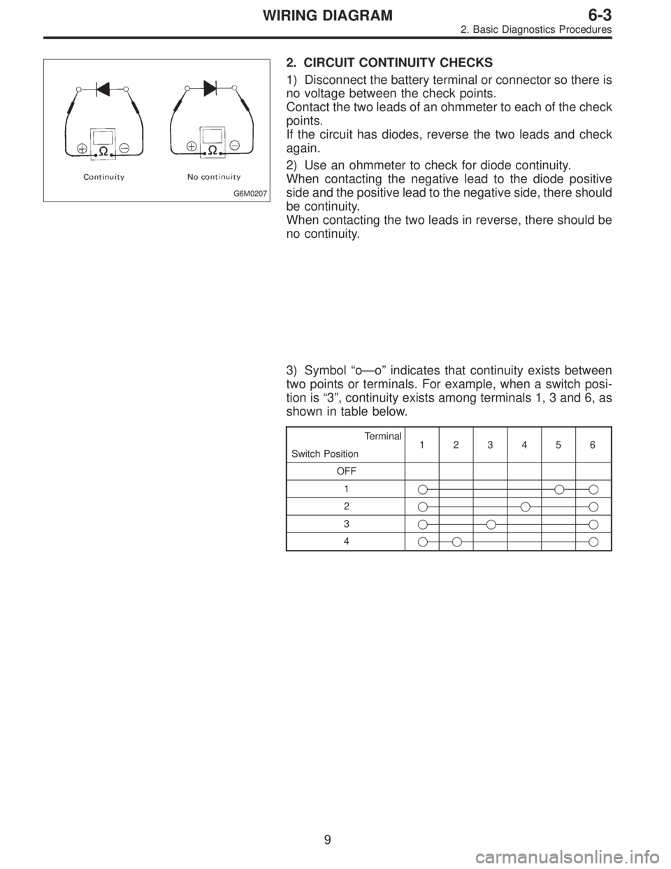
2. CIRCUIT CONTINUITY CHECKS
1) Disconnect the battery terminal or connector so there is
no voltage between the check points.
Contact the two leads of an ohmmeter to each of the check
points.
If the circuit has diodes, reverse the two leads and check
again.
2) Use an ohmmeter to check for diode continuity.
When contacting the negative lead to the diode positive
side and the positive lead to the negative side, there should
be continuity.
When contacting the two leads in reverse, there should be
no continuity.
3) Symbol“o—o”indicates that continuity exists between
two points or terminals. For example, when a switch posi-
tion is“3”, continuity exists among terminals 1, 3 and 6, as
shown in table below.
Terminal
123456
Switch Position
OFF
1��
�
2���
3���
4���
9
6-3WIRING DIAGRAM
2. Basic Diagnostics Procedures
Page 1897 of 2248
3. Working Precautions
1. PRECAUTIONS WHEN WORKING WITH THE
PARTS MOUNTED ON THE VEHICLE
1) When working under a vehicle which is jacked-up,
always be sure to use safety stands.
2) The parking brake must always be applied during work-
ing. Also, in automatic transmission vehicles, keep the
select lever set to the P (Parking) range.
3) Be sure the workshop is properly ventilated when run-
ning the engine. Further, be careful not to touch the belt or
fan while the engine is operating.
4) Be careful not to touch hot metal parts, especially the
radiator and exhaust system immediately after the engine
has been shut off.
2. PRECAUTIONS IN TROUBLE DIAGNOSIS AND
REPAIR OF ELECTRIC PARTS
1) The battery cable must be disconnected from the bat-
tery’s () terminal, and the ignition switch must be set to the
OFF position, unless otherwise required by the diagnos-
tics.
2) Securely fasten the wiring harness with clamps and
slips so that the harness does not interfere with the body
end parts or edges and bolts or screws.
3) When installing parts, be careful not to catch them on
the wiring harness.
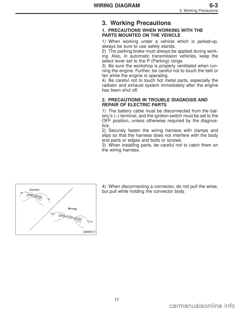
G6M0212
4) When disconnecting a connector, do not pull the wires,
but pull while holding the connector body.
11
6-3WIRING DIAGRAM
3. Working Precautions
Page 1903 of 2248
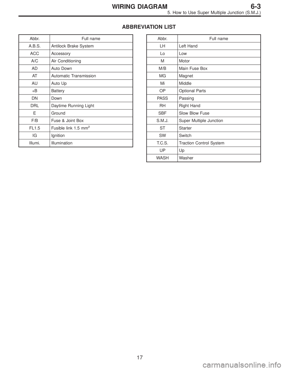
ABBREVIATION LIST
Abbr. Full name
A.B.S. Antilock Brake System
ACC Accessory
A/C Air Conditioning
AD Auto Down
AT Automatic Transmission
AU Auto Up
+B Battery
DN Down
DRL Daytime Running Light
E Ground
F/B Fuse & Joint Box
FL1.5 Fusible link 1.5 mm
2
IG Ignition
Illumi. Illumination
Abbr. Full name
LH Left Hand
Lo Low
M Motor
M/B Main Fuse Box
MG Magnet
Mi Middle
OP Optional Parts
PASS Passing
RH Right Hand
SBF Slow Blow Fuse
S.M.J. Super Multiple Junction
ST Starter
SW Switch
T.C.S. Traction Control System
UP Up
WASH Washer
17
6-3WIRING DIAGRAM
5. How to Use Super Multiple Junction (S.M.J.)
Page 1997 of 2248
3. Working Precautions
1. PRECAUTIONS WHEN WORKING WITH THE
PARTS MOUNTED ON THE VEHICLE
1) When working under a vehicle which is jacked-up,
always be sure to use safety stands.
2) The parking brake must always be applied during work-
ing. Also, in automatic transmission vehicles, keep the
select lever set to the P (Parking) range.
3) Be sure the workshop is properly ventilated when run-
ning the engine. Further, be careful not to touch the belt or
fan while the engine is operating.
4) Be careful not to touch hot metal parts, especially the
radiator and exhaust system immediately after the engine
has been shut off.
2. PRECAUTIONS IN TROUBLE DIAGNOSIS AND
REPAIR OF ELECTRIC PARTS
1) The battery cable must be disconnected from the bat-
tery’s () terminal, and the ignition switch must be set to the
OFF position, unless otherwise required by the diagnos-
tics.
2) Securely fasten the wiring harness with clamps and
slips so that the harness does not interfere with the body
end parts or edges and bolts or screws.
3) When installing parts, be careful not to catch them on
the wiring harness.
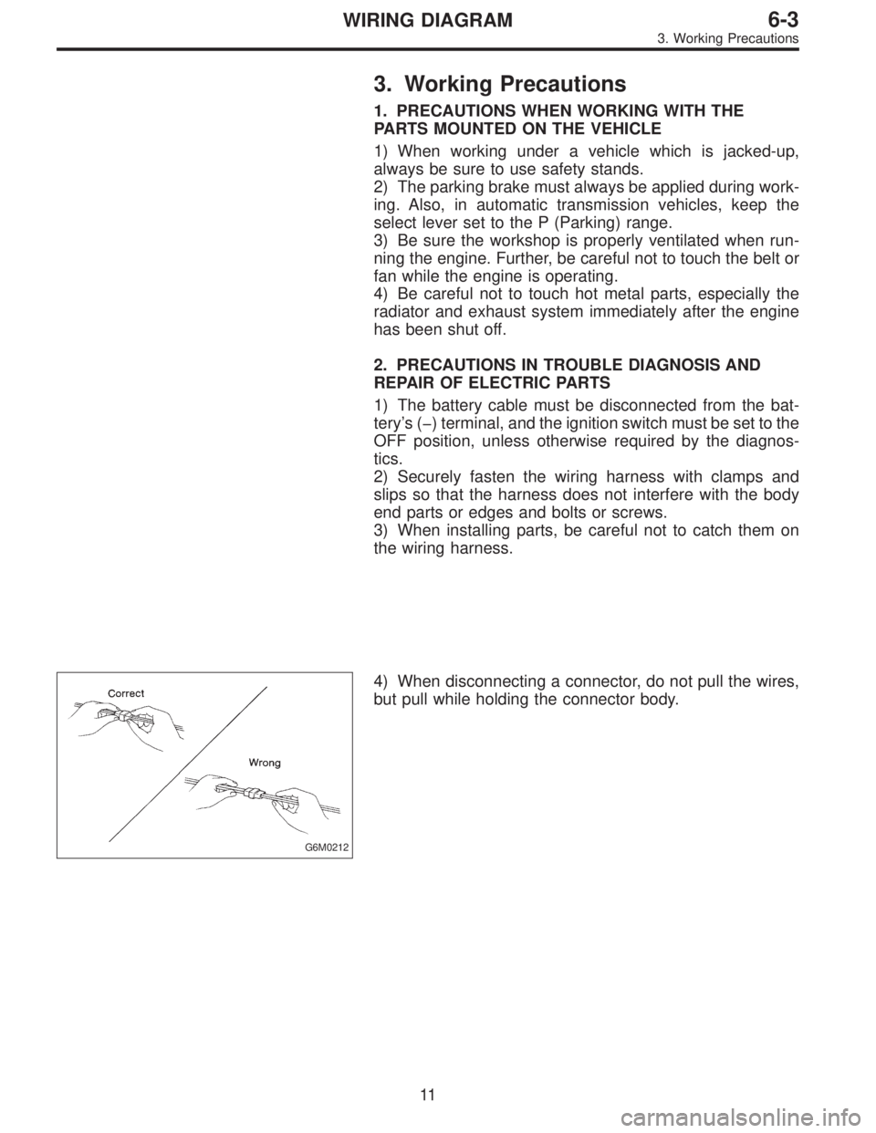
G6M0212
4) When disconnecting a connector, do not pull the wires,
but pull while holding the connector body.
11
6-3WIRING DIAGRAM
3. Working Precautions
Page 2003 of 2248
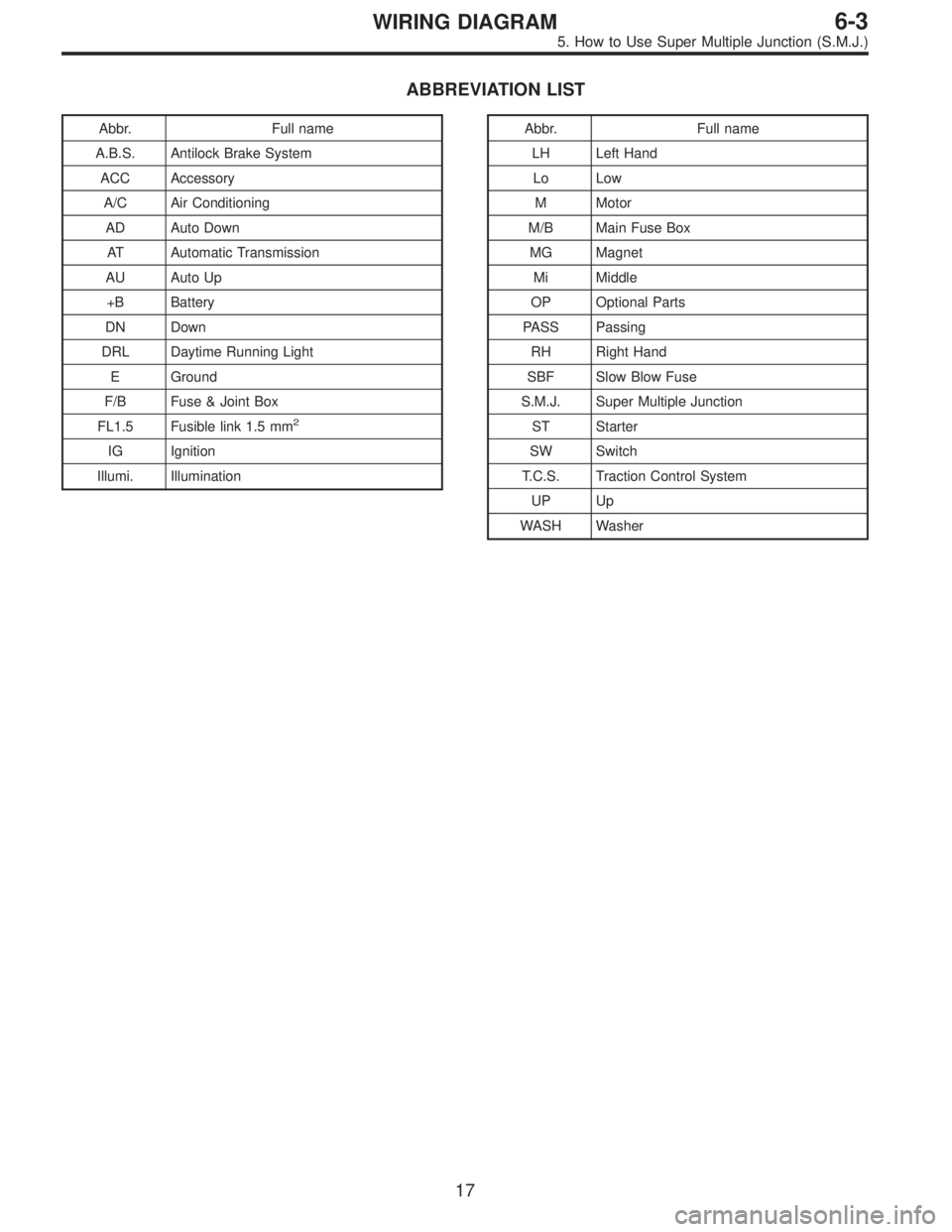
ABBREVIATION LIST
Abbr. Full name
A.B.S. Antilock Brake System
ACC Accessory
A/C Air Conditioning
AD Auto Down
AT Automatic Transmission
AU Auto Up
+B Battery
DN Down
DRL Daytime Running Light
E Ground
F/B Fuse & Joint Box
FL1.5 Fusible link 1.5 mm
2
IG Ignition
Illumi. Illumination
Abbr. Full name
LH Left Hand
Lo Low
M Motor
M/B Main Fuse Box
MG Magnet
Mi Middle
OP Optional Parts
PASS Passing
RH Right Hand
SBF Slow Blow Fuse
S.M.J. Super Multiple Junction
ST Starter
SW Switch
T.C.S. Traction Control System
UP Up
WASH Washer
17
6-3WIRING DIAGRAM
5. How to Use Super Multiple Junction (S.M.J.)
Page 2103 of 2248
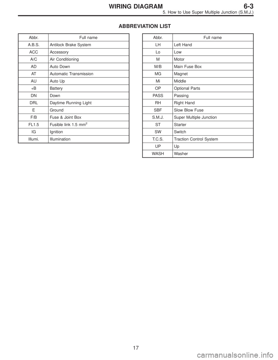
ABBREVIATION LIST
Abbr. Full name
A.B.S. Antilock Brake System
ACC Accessory
A/C Air Conditioning
AD Auto Down
AT Automatic Transmission
AU Auto Up
+B Battery
DN Down
DRL Daytime Running Light
E Ground
F/B Fuse & Joint Box
FL1.5 Fusible link 1.5 mm
2
IG Ignition
Illumi. Illumination
Abbr. Full name
LH Left Hand
Lo Low
M Motor
M/B Main Fuse Box
MG Magnet
Mi Middle
OP Optional Parts
PASS Passing
RH Right Hand
SBF Slow Blow Fuse
S.M.J. Super Multiple Junction
ST Starter
SW Switch
T.C.S. Traction Control System
UP Up
WASH Washer
17
6-3WIRING DIAGRAM
5. How to Use Super Multiple Junction (S.M.J.)