Page 585 of 2248
Drum brake: Perform steps 9) through 11).
9) Clean brake pipe connection. Using a flare-nut wrench,
connect brake pipe to wheel cylinder.
10) Connect parking brake cable to lever.
11) Install brake drum on rear housing assembly.
12) Bleed air from brake system.
13) Adjust parking brake lever stroke by turning adjuster.
14) Move brake lever back to apply brakes. While
depressing brake pedal, tighten axle nut using a socket
wrench. Lock axle nut after tightening.
Tightening torque:
186±20 N⋅m (19±2 kg-m, 137±14 ft-lb)
CAUTION:
�Use a new axle nut.
�Always tighten axle nut before installing wheel on
vehicle. If wheel is installed and comes in contact with
ground when axle nut is loose, wheel bearings may be
damaged.
�Be sure to tighten axle nut to specified torque. Do
not overtighten it as this may damage wheel bearing.
15) Install wheel and tighten wheel nuts to specified
torque.
Tightening torque:
88±10 N⋅m (9±1 kg-m, 65±7 ft-lb)
3. Rear Axle (FWD Model)
A: REMOVAL
1) Disconnect ground cable from battery.
2) Jack-up vehicle, and remove rear wheel cap and
wheels.
CAUTION:
Be sure to loosen and retighten axle nut after remov-
ing wheel from vehicle. Failure to follow this rule may
damage wheel bearings.
3) Pry hub cap off with a screwdriver placed between it
and hub.
4) Unlock axle nut.
5) Remove axle nut using a socket wrench. Remove
washer.
CAUTION:
Do not re-use old axle nut. Replace with a new one.
NOTE:
Temporarily tighten axle nut to hold hub in place.
22
4-2SERVICE PROCEDURE
2. Rear Axle (AWD Model) - 3. Rear Axle (FWD Model)
Page 586 of 2248
Drum brake: Perform steps 9) through 11).
9) Clean brake pipe connection. Using a flare-nut wrench,
connect brake pipe to wheel cylinder.
10) Connect parking brake cable to lever.
11) Install brake drum on rear housing assembly.
12) Bleed air from brake system.
13) Adjust parking brake lever stroke by turning adjuster.
14) Move brake lever back to apply brakes. While
depressing brake pedal, tighten axle nut using a socket
wrench. Lock axle nut after tightening.
Tightening torque:
186±20 N⋅m (19±2 kg-m, 137±14 ft-lb)
CAUTION:
�Use a new axle nut.
�Always tighten axle nut before installing wheel on
vehicle. If wheel is installed and comes in contact with
ground when axle nut is loose, wheel bearings may be
damaged.
�Be sure to tighten axle nut to specified torque. Do
not overtighten it as this may damage wheel bearing.
15) Install wheel and tighten wheel nuts to specified
torque.
Tightening torque:
88±10 N⋅m (9±1 kg-m, 65±7 ft-lb)
3. Rear Axle (FWD Model)
A: REMOVAL
1) Disconnect ground cable from battery.
2) Jack-up vehicle, and remove rear wheel cap and
wheels.
CAUTION:
Be sure to loosen and retighten axle nut after remov-
ing wheel from vehicle. Failure to follow this rule may
damage wheel bearings.
3) Pry hub cap off with a screwdriver placed between it
and hub.
4) Unlock axle nut.
5) Remove axle nut using a socket wrench. Remove
washer.
CAUTION:
Do not re-use old axle nut. Replace with a new one.
NOTE:
Temporarily tighten axle nut to hold hub in place.
22
4-2SERVICE PROCEDURE
2. Rear Axle (AWD Model) - 3. Rear Axle (FWD Model)
Page 591 of 2248
Tightening torque:
186±20 N⋅m (19±2 kg-m, 137±14 ft-lb)
CAUTION:
�Use a new axle nut.
�Always tighten axle nut before installing wheel on
vehicle. If wheel is installed and comes in contact with
ground when axle nut is loose, wheel bearings may be
damaged.
�Be sure to tighten axle nut to specified torque. Do
not overtighten it as this may damage wheel bearing.
12) Install O-ring to hub cap flange, and install hub cap by
lightly tapping it with a plastic-faced hammer.
13) Install wheel and tighten wheel nuts to specified
torque.
Tightening torque (Wheel nut):
88±10 N⋅m (9±1 kg-m, 65±7 ft-lb)
4. Front and Rear Drive Shafts
A: REMOVAL
1. FRONT DRIVE SHAFT
1) Disconnect ground cable from battery.
2) Jack-up vehicle, support it with safety stands (rigid
racks), and remove front wheel cap and wheels.
3) Unlock axle nut.
4) While depressing brake pedal, remove axle nut using a
socket wrench.
CAUTION:
Be sure to loosen and retighten axle nut after remov-
ing wheel from vehicle. Failure to follow this rule may
damage wheel bearings.
5) Disconnect stabilizer link from transverse link.
6) Disconnect transverse link from housing.
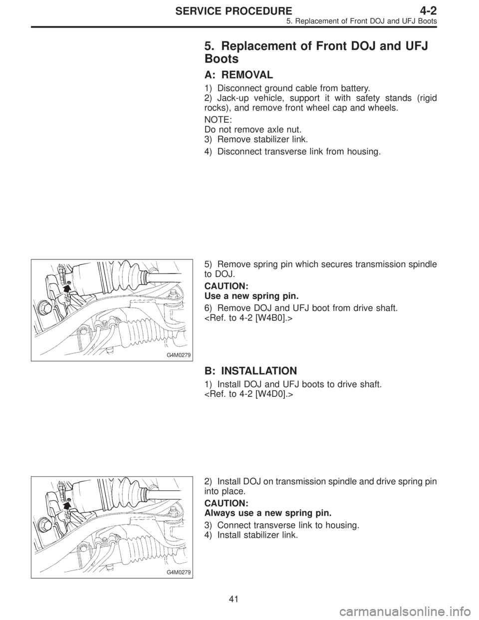
G4M0279
7) Remove spring pin which secures transmission spindle
to DOJ.
CAUTION:
Use a new spring pin.
27
4-2SERVICE PROCEDURE
3. Rear Axle (FWD) - 4. Front and Rear Drive Shafts
Page 592 of 2248
Tightening torque:
186±20 N⋅m (19±2 kg-m, 137±14 ft-lb)
CAUTION:
�Use a new axle nut.
�Always tighten axle nut before installing wheel on
vehicle. If wheel is installed and comes in contact with
ground when axle nut is loose, wheel bearings may be
damaged.
�Be sure to tighten axle nut to specified torque. Do
not overtighten it as this may damage wheel bearing.
12) Install O-ring to hub cap flange, and install hub cap by
lightly tapping it with a plastic-faced hammer.
13) Install wheel and tighten wheel nuts to specified
torque.
Tightening torque (Wheel nut):
88±10 N⋅m (9±1 kg-m, 65±7 ft-lb)
4. Front and Rear Drive Shafts
A: REMOVAL
1. FRONT DRIVE SHAFT
1) Disconnect ground cable from battery.
2) Jack-up vehicle, support it with safety stands (rigid
racks), and remove front wheel cap and wheels.
3) Unlock axle nut.
4) While depressing brake pedal, remove axle nut using a
socket wrench.
CAUTION:
Be sure to loosen and retighten axle nut after remov-
ing wheel from vehicle. Failure to follow this rule may
damage wheel bearings.
5) Disconnect stabilizer link from transverse link.
6) Disconnect transverse link from housing.
G4M0279
7) Remove spring pin which secures transmission spindle
to DOJ.
CAUTION:
Use a new spring pin.
27
4-2SERVICE PROCEDURE
3. Rear Axle (FWD) - 4. Front and Rear Drive Shafts
Page 593 of 2248
G4M0216
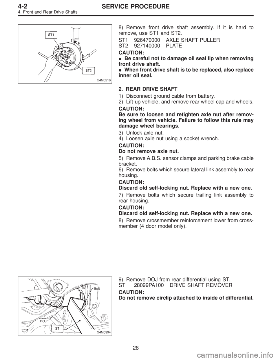
8) Remove front drive shaft assembly. If it is hard to
remove, use ST1 and ST2.
ST1 926470000 AXLE SHAFT PULLER
ST2 927140000 PLATE
CAUTION:
�Be careful not to damage oil seal lip when removing
front drive shaft.
�When front drive shaft is to be replaced, also replace
inner oil seal.
2. REAR DRIVE SHAFT
1) Disconnect ground cable from battery.
2) Lift-up vehicle, and remove rear wheel cap and wheels.
CAUTION:
Be sure to loosen and retighten axle nut after remov-
ing wheel from vehicle. Failure to follow this rule may
damage wheel bearings.
3) Unlock axle nut.
4) Loosen axle nut using a socket wrench.
CAUTION:
Do not remove axle nut.
5) Remove A.B.S. sensor clamps and parking brake cable
bracket.
6) Remove bolts which secure lateral link assembly to rear
housing.
CAUTION:
Discard old self-locking nut. Replace with a new one.
7) Remove bolts which secure trailing link assembly to
rear housing.
CAUTION:
Discard old self-locking nut. Replace with a new one.
8) Remove crossmember reinforcement lower from cross-
member (4 door model only).
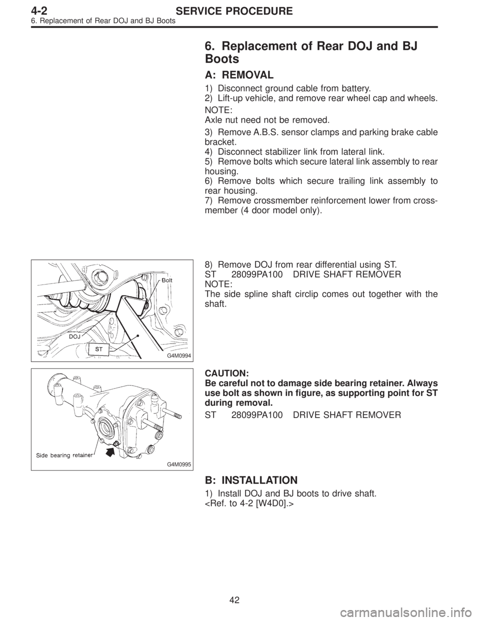
G4M0994
9) Remove DOJ from rear differential using ST.
ST 28099PA100 DRIVE SHAFT REMOVER
CAUTION:
Do not remove circlip attached to inside of differential.
28
4-2SERVICE PROCEDURE
4. Front and Rear Drive Shafts
Page 606 of 2248
5. Replacement of Front DOJ and UFJ
Boots
A: REMOVAL
1) Disconnect ground cable from battery.
2) Jack-up vehicle, support it with safety stands (rigid
rocks), and remove front wheel cap and wheels.
NOTE:
Do not remove axle nut.
3) Remove stabilizer link.
4) Disconnect transverse link from housing.
G4M0279
5) Remove spring pin which secures transmission spindle
to DOJ.
CAUTION:
Use a new spring pin.
6) Remove DOJ and UFJ boot from drive shaft.
B: INSTALLATION
1) Install DOJ and UFJ boots to drive shaft.
G4M0279
2) Install DOJ on transmission spindle and drive spring pin
into place.
CAUTION:
Always use a new spring pin.
3) Connect transverse link to housing.
4) Install stabilizer link.
41
4-2SERVICE PROCEDURE
5. Replacement of Front DOJ and UFJ Boots
Page 607 of 2248
6. Replacement of Rear DOJ and BJ
Boots
A: REMOVAL
1) Disconnect ground cable from battery.
2) Lift-up vehicle, and remove rear wheel cap and wheels.
NOTE:
Axle nut need not be removed.
3) Remove A.B.S. sensor clamps and parking brake cable
bracket.
4) Disconnect stabilizer link from lateral link.
5) Remove bolts which secure lateral link assembly to rear
housing.
6) Remove bolts which secure trailing link assembly to
rear housing.
7) Remove crossmember reinforcement lower from cross-
member (4 door model only).
G4M0994
8) Remove DOJ from rear differential using ST.
ST 28099PA100 DRIVE SHAFT REMOVER
NOTE:
The side spline shaft circlip comes out together with the
shaft.
G4M0995
CAUTION:
Be careful not to damage side bearing retainer. Always
use bolt as shown in figure, as supporting point for ST
during removal.
ST 28099PA100 DRIVE SHAFT REMOVER
B: INSTALLATION
1) Install DOJ and BJ boots to drive shaft.
42
4-2SERVICE PROCEDURE
6. Replacement of Rear DOJ and BJ Boots
Page 625 of 2248
1. Supplemental Restraint System
“Airbag”
Airbag system wiring harness is routed near the steering
wheel, steering shaft and column.
WARNING:
�All Airbag system wiring harness and connectors
are colored yellow. Do not use electrical test equip-
ment on these circuit.
�Be careful not to damage Airbag system wiring har-
ness when servicing the steering wheel, steering shaft
and column.
2. Tilt Steering Column
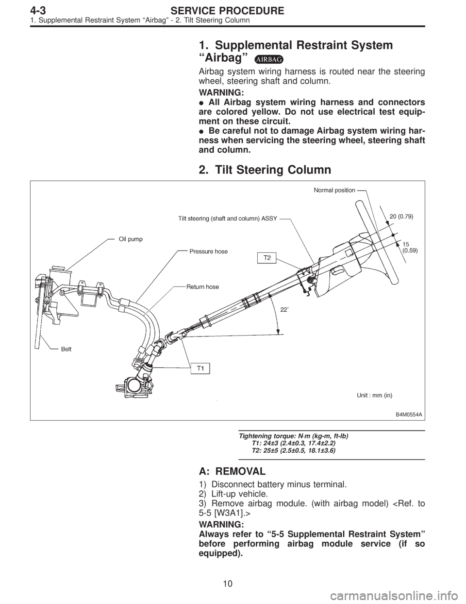
B4M0554A
Tightening torque: N⋅m (kg-m, ft-lb)
T1: 24±3 (2.4±0.3, 17.4±2.2)
T2: 25±5 (2.5±0.5, 18.1±3.6)
A: REMOVAL
1) Disconnect battery minus terminal.
2) Lift-up vehicle.
3) Remove airbag module. (with airbag model)
5-5 [W3A1].>
WARNING:
Always refer to“5-5 Supplemental Restraint System”
before performing airbag module service (if so
equipped).
10
4-3SERVICE PROCEDURE
1. Supplemental Restraint System“Airbag”- 2. Tilt Steering Column