Page 185 of 2248
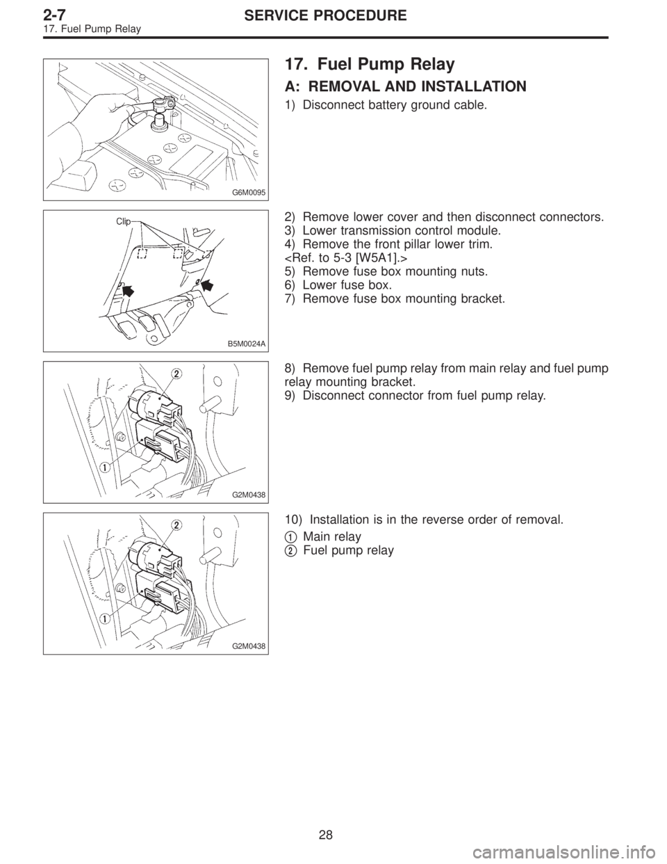
G6M0095
17. Fuel Pump Relay
A: REMOVAL AND INSTALLATION
1) Disconnect battery ground cable.
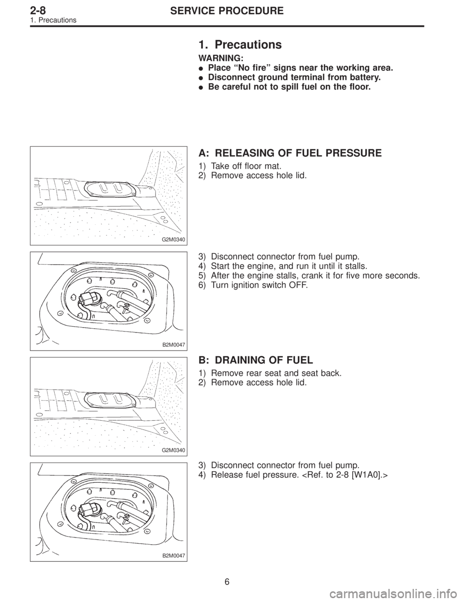
B5M0024A
2) Remove lower cover and then disconnect connectors.
3) Lower transmission control module.
4) Remove the front pillar lower trim.
5) Remove fuse box mounting nuts.
6) Lower fuse box.
7) Remove fuse box mounting bracket.
G2M0438
8) Remove fuel pump relay from main relay and fuel pump
relay mounting bracket.
9) Disconnect connector from fuel pump relay.
G2M0438
10) Installation is in the reverse order of removal.
�
1Main relay
�
2Fuel pump relay
28
2-7SERVICE PROCEDURE
17. Fuel Pump Relay
Page 190 of 2248
1. Precautions
WARNING:
�Place “No fire” signs near the working area.
�Disconnect ground terminal from battery.
�Be careful not to spill fuel on the floor.
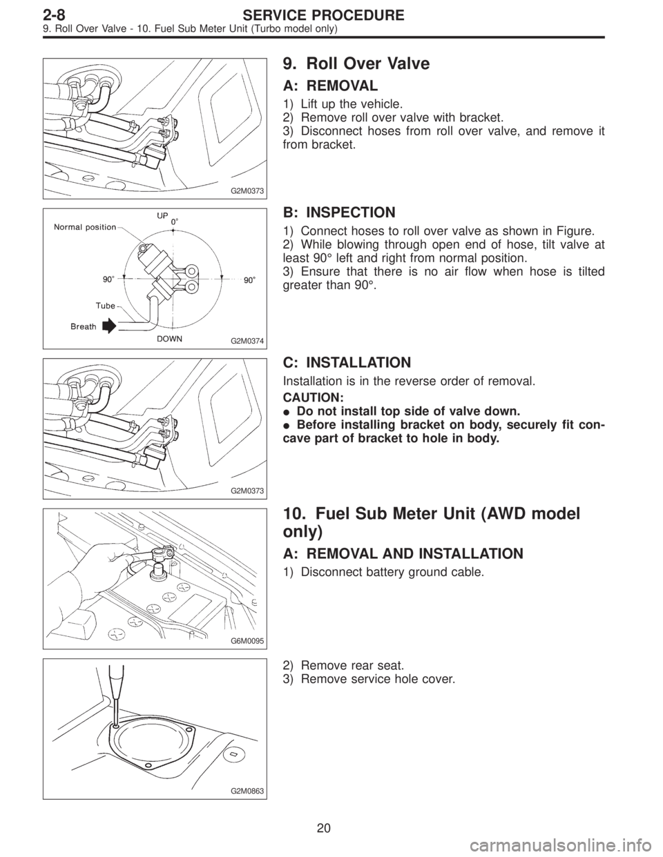
G2M0340
A: RELEASING OF FUEL PRESSURE
1) Take off floor mat.
2) Remove access hole lid.
B2M0047
3) Disconnect connector from fuel pump.
4) Start the engine, and run it until it stalls.
5) After the engine stalls, crank it for five more seconds.
6) Turn ignition switch OFF.
G2M0340
B: DRAINING OF FUEL
1) Remove rear seat and seat back.
2) Remove access hole lid.
B2M0047
3) Disconnect connector from fuel pump.
4) Release fuel pressure.
6
2-8SERVICE PROCEDURE
1. Precautions
Page 204 of 2248
G2M0366
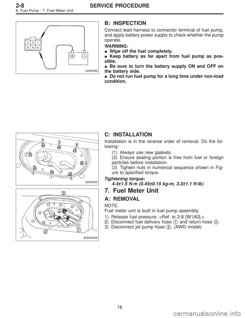
B: INSPECTION
Connect lead harness to connector terminal of fuel pump,
and apply battery power supply to check whether the pump
operate.
WARNING:
�Wipe off the fuel completely.
�Keep battery as far apart from fuel pump as pos-
sible.
�Be sure to turn the battery supply ON and OFF on
the battery side.
�Do not run fuel pump for a long time under non-load
condition.
G2M0346
C: INSTALLATION
Installation is in the reverse order of removal. Do the fol-
lowing:
(1) Always use new gaskets.
(2) Ensure sealing portion is free from fuel or foreign
particles before installation.
(3) Tighten nuts in numerical sequence shown in Fig-
ure to specified torque.
Tightening torque:
4.4±1.5 N⋅m (0.45±0.15 kg-m, 3.3±1.1 ft-lb)
B2M0048A
7. Fuel Meter Unit
A: REMOVAL
NOTE:
Fuel meter unit is built in fuel pump assembly.
1) Release fuel pressure.
2) Disconnect fuel delivery hose�
1and return hose�2.
3) Disconnect jet pump hose�
3. (AWD model)
16
2-8SERVICE PROCEDURE
6. Fuel Pump - 7. Fuel Meter Unit
Page 205 of 2248
G2M0366
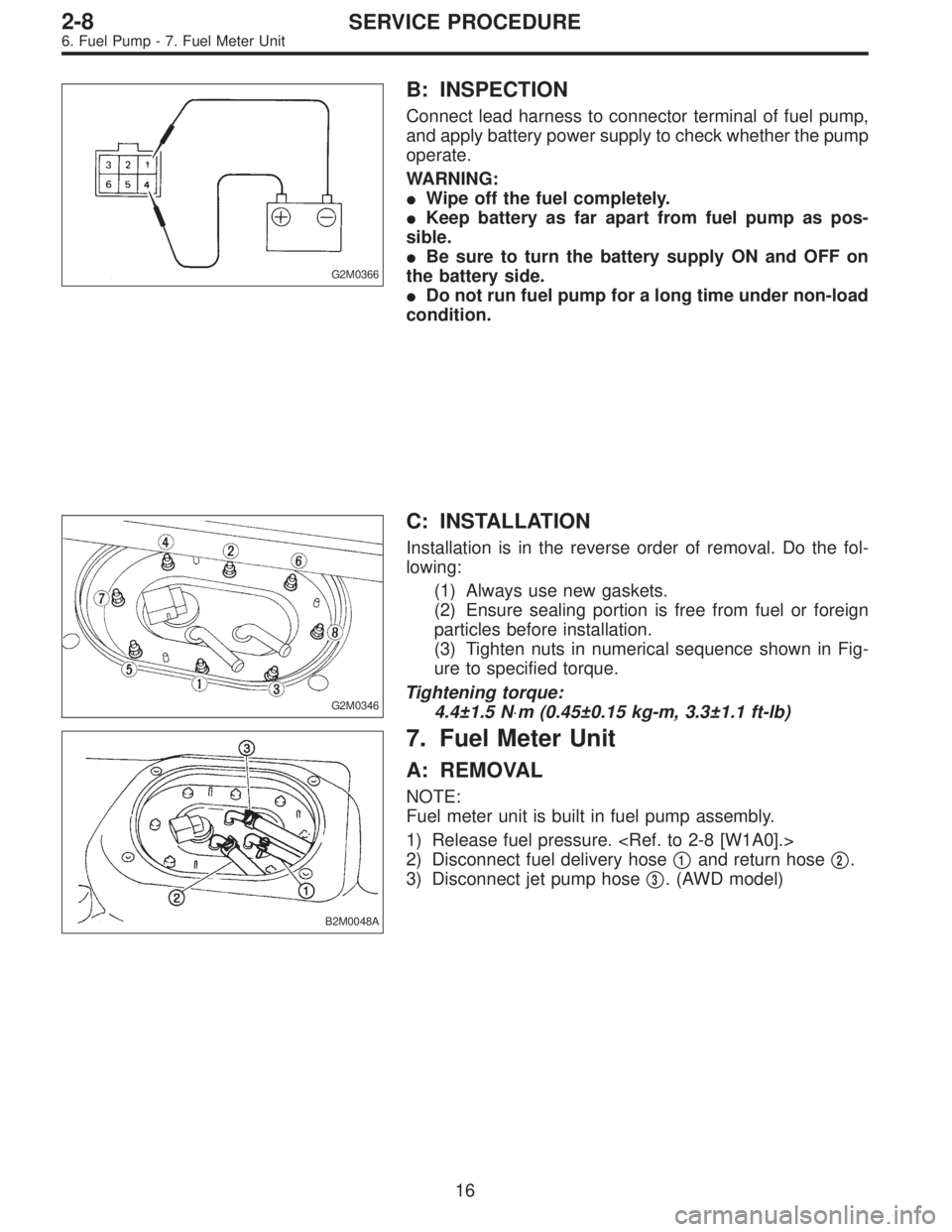
B: INSPECTION
Connect lead harness to connector terminal of fuel pump,
and apply battery power supply to check whether the pump
operate.
WARNING:
�Wipe off the fuel completely.
�Keep battery as far apart from fuel pump as pos-
sible.
�Be sure to turn the battery supply ON and OFF on
the battery side.
�Do not run fuel pump for a long time under non-load
condition.
G2M0346
C: INSTALLATION
Installation is in the reverse order of removal. Do the fol-
lowing:
(1) Always use new gaskets.
(2) Ensure sealing portion is free from fuel or foreign
particles before installation.
(3) Tighten nuts in numerical sequence shown in Fig-
ure to specified torque.
Tightening torque:
4.4±1.5 N⋅m (0.45±0.15 kg-m, 3.3±1.1 ft-lb)
B2M0048A
7. Fuel Meter Unit
A: REMOVAL
NOTE:
Fuel meter unit is built in fuel pump assembly.
1) Release fuel pressure.
2) Disconnect fuel delivery hose�
1and return hose�2.
3) Disconnect jet pump hose�
3. (AWD model)
16
2-8SERVICE PROCEDURE
6. Fuel Pump - 7. Fuel Meter Unit
Page 209 of 2248
G2M0373
9. Roll Over Valve
A: REMOVAL
1) Lift up the vehicle.
2) Remove roll over valve with bracket.
3) Disconnect hoses from roll over valve, and remove it
from bracket.
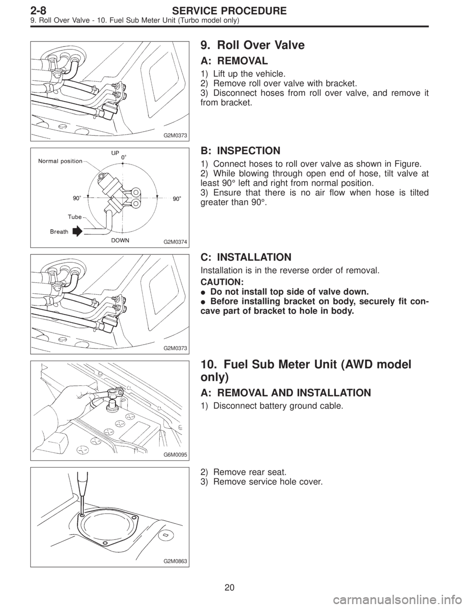
G2M0374
B: INSPECTION
1) Connect hoses to roll over valve as shown in Figure.
2) While blowing through open end of hose, tilt valve at
least 90° left and right from normal position.
3) Ensure that there is no air flow when hose is tilted
greater than 90°.
G2M0373
C: INSTALLATION
Installation is in the reverse order of removal.
CAUTION:
�Do not install top side of valve down.
�Before installing bracket on body, securely fit con-
cave part of bracket to hole in body.
G6M0095
10. Fuel Sub Meter Unit (AWD model
only)
A: REMOVAL AND INSTALLATION
1) Disconnect battery ground cable.
G2M0863
2) Remove rear seat.
3) Remove service hole cover.
20
2-8SERVICE PROCEDURE
9. Roll Over Valve - 10. Fuel Sub Meter Unit (Turbo model only)
Page 210 of 2248
G2M0373
9. Roll Over Valve
A: REMOVAL
1) Lift up the vehicle.
2) Remove roll over valve with bracket.
3) Disconnect hoses from roll over valve, and remove it
from bracket.
G2M0374
B: INSPECTION
1) Connect hoses to roll over valve as shown in Figure.
2) While blowing through open end of hose, tilt valve at
least 90° left and right from normal position.
3) Ensure that there is no air flow when hose is tilted
greater than 90°.
G2M0373
C: INSTALLATION
Installation is in the reverse order of removal.
CAUTION:
�Do not install top side of valve down.
�Before installing bracket on body, securely fit con-
cave part of bracket to hole in body.
G6M0095
10. Fuel Sub Meter Unit (AWD model
only)
A: REMOVAL AND INSTALLATION
1) Disconnect battery ground cable.
G2M0863
2) Remove rear seat.
3) Remove service hole cover.
20
2-8SERVICE PROCEDURE
9. Roll Over Valve - 10. Fuel Sub Meter Unit (Turbo model only)
Page 240 of 2248
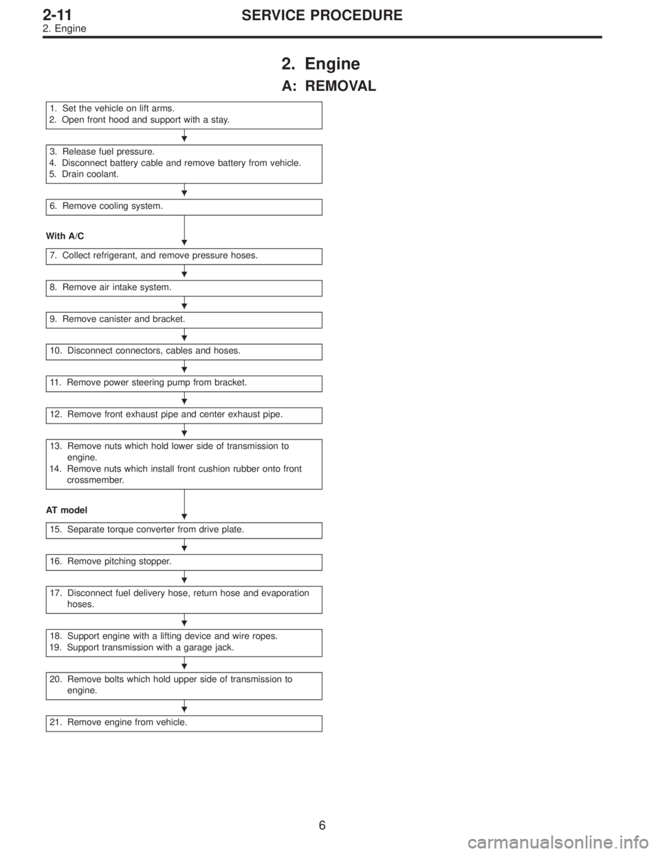
2. Engine
A: REMOVAL
1. Set the vehicle on lift arms.
2. Open front hood and support with a stay.
3. Release fuel pressure.
4. Disconnect battery cable and remove battery from vehicle.
5. Drain coolant.
6. Remove cooling system.
With A/C
7. Collect refrigerant, and remove pressure hoses.
8. Remove air intake system.
9. Remove canister and bracket.
10. Disconnect connectors, cables and hoses.
11. Remove power steering pump from bracket.
12. Remove front exhaust pipe and center exhaust pipe.
13. Remove nuts which hold lower side of transmission to
engine.
14. Remove nuts which install front cushion rubber onto front
crossmember.
AT model
15. Separate torque converter from drive plate.
16. Remove pitching stopper.
17. Disconnect fuel delivery hose, return hose and evaporation
hoses.
18. Support engine with a lifting device and wire ropes.
19. Support transmission with a garage jack.
20. Remove bolts which hold upper side of transmission to
engine.
21. Remove engine from vehicle.
�
�
�
�
�
�
�
�
�
�
�
�
�
�
�
6
2-11SERVICE PROCEDURE
2. Engine
Page 241 of 2248
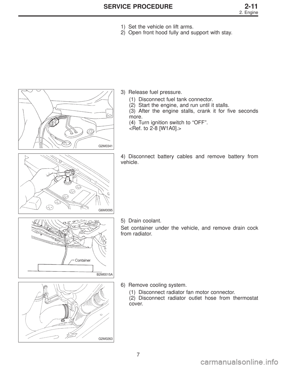
1) Set the vehicle on lift arms.
2) Open front hood fully and support with stay.
G2M0341
3) Release fuel pressure.
(1) Disconnect fuel tank connector.
(2) Start the engine, and run until it stalls.
(3) After the engine stalls, crank it for five seconds
more.
(4) Turn ignition switch to“OFF”.
G6M0095
4) Disconnect battery cables and remove battery from
vehicle.
B2M0015A
5) Drain coolant.
Set container under the vehicle, and remove drain cock
from radiator.
G2M0263
6) Remove cooling system.
(1) Disconnect radiator fan motor connector.
(2) Disconnect radiator outlet hose from thermostat
cover.
7
2-11SERVICE PROCEDURE
2. Engine