Page 536 of 2248
 Remove the wheel.
2) Pull out the cotter pin from the ball stud, remove the
castle nut, and extract the ball stud from the transverse
link.
3) Remove the bolt")
G4M0499
3. Front Ball Joint
A: REMOVAL
1) Remove the wheel.
2) Pull out the cotter pin from the ball stud, remove the
castle nut, and extract the ball stud from the transverse
link.
3) Remove the bolt securing the ball joint to the housing.
4) Extract the ball joint from the housing.
G4M0500
B: INSPECTION
1) Measure play of ball joint by the following procedures.
Replace with a new one when the play exceeds the speci-
fied value.
(1) With 686 N (70 kg, 154 lb) loaded in the direction
shown in the figure, measure dimension�
1.
G4M0501
(2) With 686 N (70 kg, 154 lb) loaded in the opposite
direction shown in the figure, measure dimension�
2.
(3) Calculate plays from the following formula.
S=�
2��1(4) When plays are larger than the following value,
replace with a new one.
FRONT BALL JOINT
Specified play for replacement: S
Less than 0.3 mm (0.012 in)
2) When play is smaller than the specified value, visually
inspect the dust cover.
3) If the dust cover is damaged, replace with the new ball
joint.
4) Check ball joint for damage and cracks. If defective,
replace with new one.
C: INSTALLATION
1) Install ball joint onto housing.
Torque (Bolt):
49±10 N⋅m (5.0±1.0 kg-m, 36±7 ft-lb)
CAUTION:
Do not apply grease to tapered portion of ball stud.
2) Connect ball joint to transverse link.
Torque (Castle nut):
39 N⋅m (4.0 kg-m, 29 ft-lb)
3) Retighten castle nut further within 60°until a slot in
castle nut is aligned with the hole of ball stud end, then
insert new cotter pin and bend it around castle nut.
4) Install front wheel.
19
4-1SERVICE PROCEDURE
3. Front Ball Joint
Page 542 of 2248
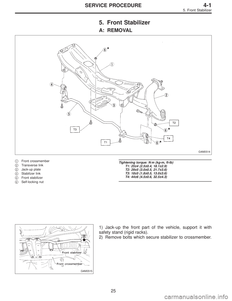
5. Front Stabilizer
A: REMOVAL
G4M0514
�1Front crossmember
�
2Transverse link
�
3Jack-up plate
�
4Stabilizer link
�
5Front stabilizer
�
6Self-locking nut
Tightening torque: N⋅m (kg-m, ft-lb)
T1: 25±4 (2.5±0.4, 18.1±2.9)
T2: 29±5 (3.0±0.5, 21.7±3.6)
T3: 18±5 (1.8±0.5, 13.0±3.6)
T4: 44±6 (4.5±0.6, 32.5±4.3)
G4M0515
1) Jack-up the front part of the vehicle, support it with
safety stand (rigid racks).
2) Remove bolts which secure stabilizer to crossmember.
25
4-1SERVICE PROCEDURE
5. Front Stabilizer
Page 543 of 2248
 Remove bolts which secure stabilizer link to front trans-
verse link.
4) Remove jack-up plate from lower part of crossmember.
B: INSPECTION
1) Check bushing for cracks, fatigue or damage.
2")
G4M0516
3) Remove bolts which secure stabilizer link to front trans-
verse link.
4) Remove jack-up plate from lower part of crossmember.
B: INSPECTION
1) Check bushing for cracks, fatigue or damage.
2) Check stabilizer link for deformities, cracks, or damage,
and bushing for protrusions from the hole of stabilizer link
and its play.
G4M0519
C: INSTALLATION
1) To install, reverse the removal procedure.
NOTE:
�Install bushing (on front crossmember side) while align-
ing it with paint mark on stabilizer.
�Ensure that bushing and stabilizer have the same iden-
tification colors when installing.
2) Always tighten rubber bushing location when wheels
are in full contact with the ground and vehicle is at curb
weight condition.
Tightening torque:
Jack-up plate to crossmember:
18±5 N⋅m (1.8±0.5 kg-m, 13.0±3.6 ft-lb)
Stabilizer link to front transverse link:
29±5 N⋅m (3.0±0.5 kg-m, 21.7±3.6 ft-lb)
Stabilizer to crossmember:
25±4 N⋅m (2.5±0.4 kg-m, 18.1±2.9 ft-lb)
26
4-1SERVICE PROCEDURE
5. Front Stabilizer
Page 544 of 2248
 Disconnect ground cable from battery.
2) Loosen front wheel nuts.
3) Lift-up vehicle, and remove front tires and wheels.
4) Remove both stabilizer and jack-u")
G4M0520
6. Front Crossmember
A: REMOVAL
1) Disconnect ground cable from battery.
2) Loosen front wheel nuts.
3) Lift-up vehicle, and remove front tires and wheels.
4) Remove both stabilizer and jack-up plate.
5) Disconnect tie-rod end from housing.
6) Remove front exhaust pipe.
G4M0521
7) Remove front transverse link from front crossmember
and body.
8) Remove nuts attaching engine mount cushion rubber to
crossmember.
9) Remove self-locking nuts connecting steering U/J and
pinion shaft.
10) Lift engine by approx. 10 mm (0.39 in) by using chain
block.
11) Support crossmember with a jack, remove nuts secur-
ing crossmember to body and lower crossmember gradu-
ally along with steering gearbox.
CAUTION:
When removing crossmember downward, be careful
that tie-rod end does not interfere with DOJ boot.
B: INSTALLATION
1) Installation is in the reverse order of removal proce-
dures.
CAUTION:
Always tighten rubber bushing when wheels are in full
contact with the ground and vehicle is at curb weight
condition.
Tightening torque:
Transverse link bushing to crossmember:
98±15 N⋅m (10.0±1.5 kg-m, 72±11 ft-lb)
Stabilizer to bushing:
25±4 N⋅m (2.5±0.4 kg-m, 18.1±2.9 ft-lb)
Tie-rod end to housing:
27.0±2.5 N⋅m (2.75±0.25 kg-m, 19.9±1.8 ft-lb)
Front cushion rubber to crossmember:
69±15 N⋅m (7.0±1.5 kg-m, 51±11 ft-lb)
Universal joint to pinion shaft:
24±3 N⋅m (2.4±0.3 kg-m, 17.4±2.2 ft-lb)
Crossmember to body:
98±15 N⋅m (10.0±1.5 kg-m, 72±11 ft-lb)
2) Purge air from power steering system.
NOTE:
Check wheel alignment and adjust if necessary.
27
4-1SERVICE PROCEDURE
6. Front Crossmember
Page 551 of 2248
 Loosen wheel nuts. Lift-up vehicle and remove wheel.
2) Remove rear exhaust pipe and muffler.
3) Remove stabilizer link from rear lateral link.
4) Scribe an aligning mark on ad")
G4M0529
1. FWD MODEL
1) Loosen wheel nuts. Lift-up vehicle and remove wheel.
2) Remove rear exhaust pipe and muffler.
3) Remove stabilizer link from rear lateral link.
4) Scribe an aligning mark on adjusting bolt, adjusting
wheel and crossmember.
5) Remove bolts securing lateral links to housing.
6) Turn cap (lateral link) counterclockwise until it contacts
stopper, then remove cap.
7) While holding adjusting bolt’s head with a wrench,
loosen self-locking nut.
CAUTION:
Always loosen self-locking nut before turning adjust-
ing bolt.
8) Lateral link removal
(1) Left lateral links
Remove adjusting bolt and front and rear lateral links.
(2) Right lateral links
Support crossmember with transmission jack.
Remove bolts securing crossmember to vehicle body.
Lower transmission jack until adjusting bolt can be
removed. Remove adjusting bolt, front and rear lateral
links.
2. AWD MODEL
1) Loosen wheel nuts. Lift-up vehicle and remove wheel.
2) Remove stabilizers link from lateral link.
3) Remove A.B.S. sensor harness from trailing link.
(A.B.S. equipped models.)
B4M0573A
4) Remove bolt securing trailing link to housing.
5) Remove DOJ from differential.
6) Scribe an alignment mark on rear lateral link adjusting
bolt and crossmember.
7) Remove bolt securing lateral link to housing.
8) Remove bolts securing front and rear lateral links to
crossmember, detach lateral links.
CAUTION:
To loosen adjusting bolt, always loosen nut while hold-
ing the head of adjusting bolt.
34
4-1SERVICE PROCEDURE
8. Lateral Link
Page 562 of 2248
G4M0544
5) Place transmission jack under rear crossmember.
G4M0545
6) Remove bolts securing crossmember to vehicle body,
and remove crossmember.
7) Scribe an alignment mark on rear lateral link cam bolt
and crossmember.
8) Remove four bolts securing front and rear lateral links
to crossmember by loosening nuts.
B: INSPECTION
Check removed parts for damage and cracks, and correct
or replace if defective.
C: INSTALLATION
1) Install in reverse order of removal.
2) For installation and tightening torque of rear differential,
refer to 3-4 [W2F0].
CAUTION:
Always tighten rubber bushing when wheels are in full
contact with the ground and vehicle is at curb weight
condition.
NOTE:
Check wheel alignment and adjust if necessary.
45
4-1SERVICE PROCEDURE
11. Rear Crossmember (AWD Model)
Page 570 of 2248
1. Front Axle
A: REMOVAL
1) Disconnect ground cable from battery.
2) Jack-up vehicle, support it with safety stands, and
remove front wheels.
G4M0214
3) Unlock axle nut.
4) Remove axle nut using a socket wrench.
CAUTION:
Be sure to loose and retighten axle nut after removing
wheel from vehicle. Failure to follow this rule may dam-
age wheel bearings.
G4M0215
5) Remove stabilizer link.
G4M0216
6) Remove DOJ from transmission spindle.
7) Remove front drive shaft assembly from hub. If it is hard
to remove, use STs.
ST1 926470000 AXLE SHAFT PULLER
ST2 927140000 PLATE
CAUTION:
�Be careful not to damage oil seal lip when removing
front drive shaft.
�When replacing front drive shaft, also replace inner
oil seal.
8) Remove disc brake caliper from housing, and suspend
it from strut using a wire.
8
4-2SERVICE PROCEDURE
1. Front Axle
Page 571 of 2248
G4M0217
9) Remove disc rotor from hub.
If disc rotor seizes up within hub, drive disc rotor out by
installing an 8-mm bolt in screw hole on the rotor.
G4M0218
10) Remove cotter pin and castle nut which secure tie-rod
end to housing knuckle arm.
G4M0219
11) Using a puller, remove tie-rod ball joint from knuckle
arm.
G4M0220
12) On A.B.S. equipped models, remove A.B.S. sensor
assembly and harness in advance.
CAUTION:
Be sure to use soft jaws (such as aluminum plates)
when placing the mating surfaces of housing and strut
in a vise.
G4M0221
13) Remove transverse link ball joint from housing.
9
4-2SERVICE PROCEDURE
1. Front Axle
 Place transmission jack under rear crossmember.
G4M0545
6) Remove bolts securing crossmember to vehicle body,
and remove crossmember.
7) Scribe an alignment mark on rear lateral link cam bo")
 Disconnect ground cable from battery.
2) Jack-up vehicle, support it with safety stands, and
remove front wheels.
G4M0214
3) Unlock axle nut.
4) Remove axle nut using a soc")
 Remove disc rotor from hub.
If disc rotor seizes up within hub, drive disc rotor out by
installing an 8-mm bolt in screw hole on the rotor.
G4M0218
10) Remove cotter pin and castle nut whic")