Page 459 of 2248
G3M0505
7) Coat the seal ring with vaseline, and install it in the seal
ring groove of the shaft.
CAUTION:
Do not expand the seal ring excessively when install-
ing.
ST 899580100 INSTALLER
G3M0913
16. Transfer Valve Body
A: DISASSEMBLY
1) Remove the plate. Then remove the spring and pilot
valve together.
2) Remove the straight pin and pry out the plug with a
screwdriver. Then extract the spring and transfer clutch
valve together.
CAUTION:
Be careful not to damage the valve and valve body.
B: INSPECTION
Check each component for harmful cuts, damage, or other
faults.
C: ASSEMBLY
To assemble, reverse the removal sequence.
NOTE:
Make sure the valve slides smoothly after assembling.
11 2
3-2SERVICE PROCEDURE
15. Transfer Clutch - 16. Transfer Valve Body
Page 460 of 2248
G3M0505
7) Coat the seal ring with vaseline, and install it in the seal
ring groove of the shaft.
CAUTION:
Do not expand the seal ring excessively when install-
ing.
ST 899580100 INSTALLER
G3M0913
16. Transfer Valve Body
A: DISASSEMBLY
1) Remove the plate. Then remove the spring and pilot
valve together.
2) Remove the straight pin and pry out the plug with a
screwdriver. Then extract the spring and transfer clutch
valve together.
CAUTION:
Be careful not to damage the valve and valve body.
B: INSPECTION
Check each component for harmful cuts, damage, or other
faults.
C: ASSEMBLY
To assemble, reverse the removal sequence.
NOTE:
Make sure the valve slides smoothly after assembling.
11 2
3-2SERVICE PROCEDURE
15. Transfer Clutch - 16. Transfer Valve Body
Page 461 of 2248
G6M0095
17. Transmission Control Module
A: REMOVAL
1) Disconnect battery ground cable.
B3M0377A
2) Remove lower cover and then disconnect connector.
OBD0040
3) Remove TCM from steering support beam.
4) Disconnect connectors form TCM�
1.
OBD0040
B: INSTALLATION
1) Connect connectors to TCM�1.
2) Install TCM to steering support beam.
Tightening torque:
7.4±2.0 N⋅m (0.75±0.2 kg-m, 5.4±1.4 ft-lb)
3) Installing procedure hereafter is in the reverse order of
removal.
11 3
3-2SERVICE PROCEDURE
17. Transmission Control Module
Page 462 of 2248
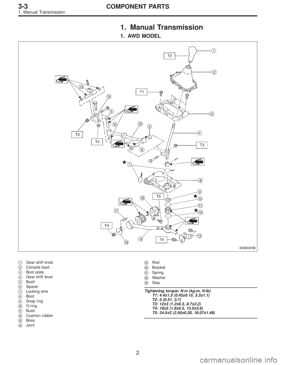
1. Manual Transmission
1. AWD MODEL
B3M0005B
�1Gear shift knob
�
2Console boot
�
3Boot plate
�
4Gear shift lever
�
5Bush
�
6Spacer
�
7Locking wire
�
8Boot
�
9Snap ring
�
10O-ring
�
11Bush
�
12Cushion rubber
�
13Boss
�
14Joint�
15Rod
�
16Bracket
�
17Spring
�
18Washer
�
19Stay
Tightening torque: N⋅m (kg-m, ft-lb)
T1: 4.4±1.5 (0.45±0.15, 3.3±1.1)
T2: 5 (0.51, 3.7)
T3: 12±3 (1.2±0.3, 8.7±2.2)
T4: 18±5 (1.8±0.5, 13.0±3.6)
T5: 24.5±2 (2.50±0.20, 18.07±1.48)
2
3-3COMPONENT PARTS
1. Manual Transmission
Page 463 of 2248
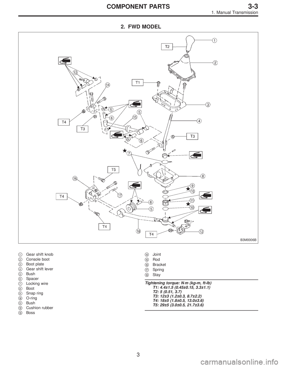
2. FWD MODEL
B3M0006B
�1Gear shift knob
�
2Console boot
�
3Boot plate
�
4Gear shift lever
�
5Bush
�
6Spacer
�
7Locking wire
�
8Boot
�
9Snap ring
�
10O-ring
�
11Bush
�
12Cushion rubber
�
13Boss�
14Joint
�
15Rod
�
16Bracket
�
17Spring
�
18Stay
Tightening torque: N⋅m (kg-m, ft-lb)
T1: 4.4±1.5 (0.45±0.15, 3.3±1.1)
T2: 5 (0.51, 3.7)
T3: 12±3 (1.2±0.3, 8.7±2.2)
T4: 18±5 (1.8±0.5, 13.0±3.6)
T5: 29±5 (3.0±0.5, 21.7±3.6)
3
3-3COMPONENT PARTS
1. Manual Transmission
Page 464 of 2248
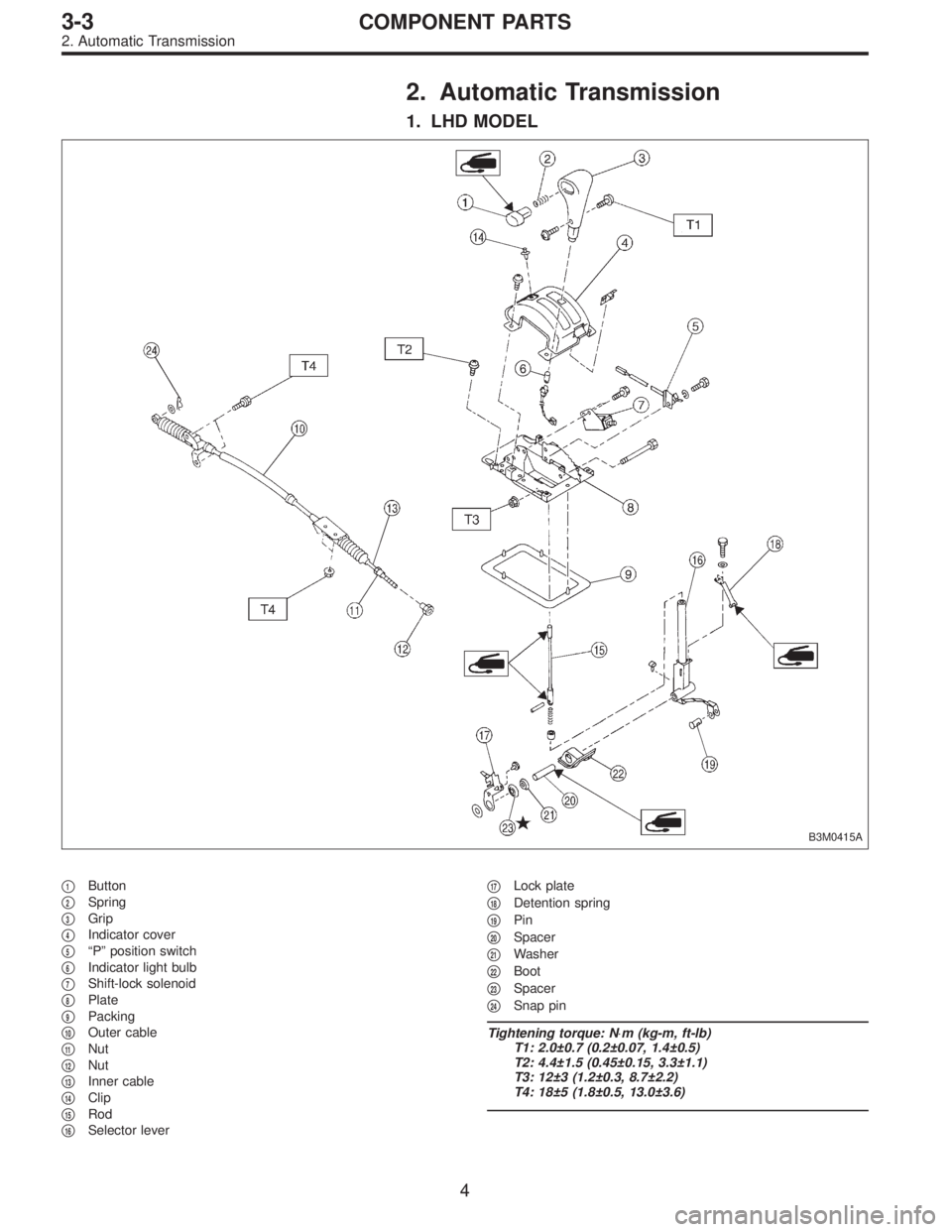
2. Automatic Transmission
1. LHD MODEL
B3M0415A
�1Button
�
2Spring
�
3Grip
�
4Indicator cover
�
5“P” position switch
�
6Indicator light bulb
�
7Shift-lock solenoid
�
8Plate
�
9Packing
�
10Outer cable
�
11Nut
�
12Nut
�
13Inner cable
�
14Clip
�
15Rod
�
16Selector lever�
17Lock plate
�
18Detention spring
�
19Pin
�
20Spacer
�
21Washer
�
22Boot
�
23Spacer
�
24Snap pin
Tightening torque: N⋅m (kg-m, ft-lb)
T1: 2.0±0.7 (0.2±0.07, 1.4±0.5)
T2: 4.4±1.5 (0.45±0.15, 3.3±1.1)
T3: 12±3 (1.2±0.3, 8.7±2.2)
T4: 18±5 (1.8±0.5, 13.0±3.6)
4
3-3COMPONENT PARTS
2. Automatic Transmission
Page 465 of 2248
2. RHD MODEL
B3M0385A
�1Grip
�
2Spring
�
3Button
�
4Indicator cover
�
5“P”position switch
�
6Indicator light bulb
�
7Shift-lock solenoid
�
8Plate
�
9Packing
�
10Outer cable
�
11Nut
�
12Nut
�
13Inner cable
�
14Clip
�
15Rod�
16Selector lever
�
17Lock plate
�
18Detention spring
�
19Pin
�
20Spacer
�
21Washer
�
22Boot
�
23Spacer
�
24Snap pin
Tightening torque: N⋅m (kg-m, ft-lb)
T1: 4.4±1.5 (0.45±0.15, 3.3±1.1)
T2: 12±3 (1.2±0.3, 8.7±2.2)
T3: 18±5 (1.8±0.5, 13.0±3.6)
5
3-3COMPONENT PARTS
2. Automatic Transmission
Page 466 of 2248
1. Manual Transmission
A: REMOVAL
1) Remove console box.
B3M0009
2) Remove boot plate from the body.
G3M0680
3) Remove the spring between the joint and bracket.
G3M0681
4) Remove stay from bracket.
G3M0682
5) Remove rod from joint.
6
3-3SERVICE PROCEDURE
1. Manual Transmission
 Coat the seal ring with vaseline, and install it in the seal
ring groove of the shaft.
CAUTION:
Do not expand the seal ring excessively when install-
ing.
ST 899580100 INSTALLER
G3M0913
16.")
 Coat the seal ring with vaseline, and install it in the seal
ring groove of the shaft.
CAUTION:
Do not expand the seal ring excessively when install-
ing.
ST 899580100 INSTALLER
G3M0913
16.")
 Disconnect battery ground cable.
B3M0377A
2) Remove lower cover and then disconnect connector.
OBD0040
3) Remove TCM from steering support beam.
4")

![SUBARU LEGACY 1995 Service Repair Manual 1. Manual Transmission
A: REMOVAL
1) Remove console box. <Ref. to 5-4 [W1A0].>
B3M0009
2) Remove boot plate from the body.
G3M0680
3) Remove the spring between the joint and bracket.
G3M0681
4) Remove](/manual-img/17/57432/w960_57432-465.png "SUBARU LEGACY 1995 Service Repair Manual 1. Manual Transmission
A: REMOVAL
1) Remove console box. <Ref. to 5-4 [W1A0].>
B3M0009
2) Remove boot plate from the body.
G3M0680
3) Remove the spring between the joint and bracket.
G3M0681
4) Remove")