Page 475 of 2248
G3M0710
4) Assemble detention spring, shift-lock solenoid and“P”
position switch.
G3M0711
5) Adjust the position of shift-lock plate and solenoid.
Then, tighten bolts.
G3M0712
6) Assemble indicator to the plate
Tightening torque:
4.4±1.5 N⋅m (0.45±0.15 kg-m, 3.3±1.1 ft-lb)
B3M0347A
7) Assemble the following parts to the grip.
CAUTION:
Apply grease on sliding surfaces of the following
parts.
�
1Button
�
2Spring
G3M0714
8) Assemble the grip to the selector lever.
14
3-3SERVICE PROCEDURE
2. Automatic Transmission
Page 476 of 2248
9) After completion of fitting, transfer selector lever to
range“P”∼“1”, pressing the button of the grip; then check
whether the indicator and select lever agree, whether the
pointer and position mark agree and what the operating
force is.
G3M0703
E: INSTALLATION
1) Mount the selector lever onto the vehicle body.
2) Tighten the six bolts to install the selector lever to the
vehicle body.
Tightening torque:
4.5±1.5 N⋅m (0.45±0.15 kg-m, 3.3±1.1 ft-lb)
G3M0702
3) Connect connectors and install rear console, center
console and instrument console.
G3M0715
4) Set location of selector lever at“N”position.
5) Set location of selector arm installed on the transmis-
sion body at“N”position.
B3M0416A
6) Pass inner cable through selector arm pin and then
connect it using a washer and snap pin.
7) Attach outer cable to plate on transmission case with
the bolts.
Tightening torque:
18±5 N⋅m (1.8±0.5 kg-m, 13.0±3.6 ft-lb)
15
3-3SERVICE PROCEDURE
2. Automatic Transmission
Page 477 of 2248
 Insert the thread portion of the other inner cable end
into the connector hole of the selector lever, and fix the
other outer cable end to the bracket.
9) Adjust the inner cable length.
(1")
B3M0417A
8) Insert the thread portion of the other inner cable end
into the connector hole of the selector lever, and fix the
other outer cable end to the bracket.
9) Adjust the inner cable length.
(1) Put connector into contact with nut�
2.
(2) Tighten nut�
1.
Tightening torque:
7.4±2.0 N⋅m (0.75±0.2 kg-m, 5.4±1.4 ft-lb)
10) After completion of fitting, make sure that the selector
lever operates smoothly all across the operating range.
11) Connect the harnesses and check the following items.
(1) The engine starts operating when selector lever is
in position“P”, but not in other positions.
(2) The back-up light is lit when the selector lever is in
position“R”, but not in other positions.
B3M0348A
12) Check selector lever operation.
WARNING:
Stop the engine while checking operation of selector
lever.
(1) Check that selector lever does not move from“N”
to“R”without pushing the button.
(2) Check that selector lever does not move from“R”
to“P”without pushing the button.
(3) Check that selector lever does not move from“P”
to“R”without pushing the button and the brake pedal
depressed. [With ignition key set at“ON”.]
(4) Check that selector lever does not move from“3”to
“2”without pushing the button.
13) Check shift-lock system.
(1) Ensure ignition switch rotates from“ACC”to
“LOCK”when the selector lever is set at“P”. Also check
that ignition key can be removed from the“LOCK”posi-
tion only.
(2) Ensure selector lever moves from“P”to any other
position when the brake pedal is depressed with igni-
tion key set at“ON”or“START”.
16
3-3SERVICE PROCEDURE
2. Automatic Transmission
Page 486 of 2248
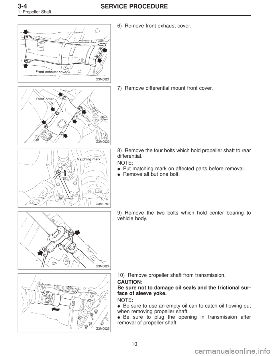
G3M0021
6) Remove front exhaust cover.
G3M0022
7) Remove differential mount front cover.
G3M0782
8) Remove the four bolts which hold propeller shaft to rear
differential.
NOTE:
�Put matching mark on affected parts before removal.
�Remove all but one bolt.
G3M0024
9) Remove the two bolts which hold center bearing to
vehicle body.
G3M0025
10) Remove propeller shaft from transmission.
CAUTION:
Be sure not to damage oil seals and the frictional sur-
face of sleeve yoke.
NOTE:
�Be sure to use an empty oil can to catch oil flowing out
when removing propeller shaft.
�Be sure to plug the opening in transmission after
removal of propeller shaft.
10
3-4SERVICE PROCEDURE
1. Propeller Shaft
Page 487 of 2248
G3M0026
11) Install the extension cap to transmission.
G3M0027
C: DISASSEMBLY
Before removing center bearing, check its condition. If it
does not operate smoothly or if there is any free play or
leakage, remove as follows:
1) Put matching marks on affected parts.
G3M0028
2) Remove bolts which hold front propeller shaft to rear
propeller shaft.
G3M0029
3) Place companion flange in a vise and remove stake nut.
CAUTION:
Be sure not to hold propeller shaft pipe portion in the
vise.
G3M0030
4) Drive out companion flange with a puller or press.
NOTE:
Before disassembling, put matching mark on affected
parts.
11
3-4SERVICE PROCEDURE
1. Propeller Shaft
Page 489 of 2248
G3M0027
4) Align matching marks and connect front and rear pro-
peller shafts.
Tightening torque:
27.9±4.4 N⋅m (2.85±0.45 kg-m, 20.6±3.3 ft-lb)
G3M0024
F: INSTALLATION
1) Insert sleeve yoke into transmission and attach center
bearing to vehicle body.
Tightening torque:
52±5 N⋅m (5.3±0.5 kg-m, 38.3±3.6 ft-lb)
G3M0782
2) Align matching marks and connect flange yoke and rear
differential.
Tightening torque:
31±8 N⋅m (3.2±0.8 kg-m, 23.1±5.8 ft-lb)
G3M0022
3) Install differential mount front cover.
Tightening torque:
88±10 N⋅m (9.0±1.0 kg-m, 65±7 ft-lb)
G3M0021
4) Install front exhaust cover.
5) Install rear exhaust pipe and muffler.
13
3-4SERVICE PROCEDURE
1. Propeller Shaft
Page 495 of 2248
B: REMOVAL
1) Disconnect ground cable from battery.
2) Move selector lever or gear shift lever to“N”.
3) Release the parking brake.
4) Loosen wheel nuts.
5) Jack-up vehicle and support it with sturdy racks.
6) Remove wheels.
7) Remove rear exhaust pipe and muffler.
G3M0021
8) Remove front exhaust cover.
G3M0022
9) Remove front cover of rear differential mount.
G3M0024
10) Remove propeller shaft.
CAUTION:
When removing propeller shaft, pay attention not to
damage the sliding surfaces of rear drive shaft (exten-
sion) spline, oil seal and sleeve yoke.
NOTE:
Prepare an oil can and cap since the transmission oil flows
out from the extension at removing propeller shaft.
G3M0026
NOTE:
Insert the cap into the extension to prevent transmission oil
from flowing out immediately after removing the propeller
shaft.
19
3-4SERVICE PROCEDURE
2. Rear Differential
Page 496 of 2248
G3M0053
11) Remove heat sealed cover.
12) Remove clamps and bracket of parking brake cable.
13) Remove crossmember reinforcement lower (AWD
Sedan only).
G3M1020
14) Remove DOJ of rear drive shaft from rear differential
using ST.
ST 28099PA100 DRIVE SHAFT REMOVER
G3M1022
15) Secure rear drive shaft to rear crossmember using
wire.
G3M0054
16) Remove lower differential bracket.
G3M0055
17) Support rear differential with transmission jack.
20
3-4SERVICE PROCEDURE
2. Rear Differential
 Assemble detention spring, shift-lock solenoid and“P”
position switch.
G3M0711
5) Adjust the position of shift-lock plate and solenoid.
Then, tighten bolts.
G3M0712
6) Assemble indicato")
 After completion of fitting, transfer selector lever to
range“P”∼“1”, pressing the button of the grip; then check
whether the indicator and select lever agree, whether the
pointer and pos")
 Install the extension cap to transmission.
G3M0027
C: DISASSEMBLY
Before removing center bearing, check its condition. If it
does not operate smoothly or if there is any free play or
leaka")
 Align matching marks and connect front and rear pro-
peller shafts.
Tightening torque:
27.9±4.4 N⋅m (2.85±0.45 kg-m, 20.6±3.3 ft-lb)
G3M0024
F: INSTALLATION
1) Insert sleeve yoke into")
 Disconnect ground cable from battery.
2) Move selector lever or gear shift lever to“N”.
3) Release the parking brake.
4) Loosen wheel nuts.
5) Jack-up vehicle and support it with stu")
 Remove heat sealed cover.
12) Remove clamps and bracket of parking brake cable.
13) Remove crossmember reinforcement lower (AWD
Sedan only).
G3M1020
14) Remove DOJ of rear drive shaft from")