Page 497 of 2248
G3M1028
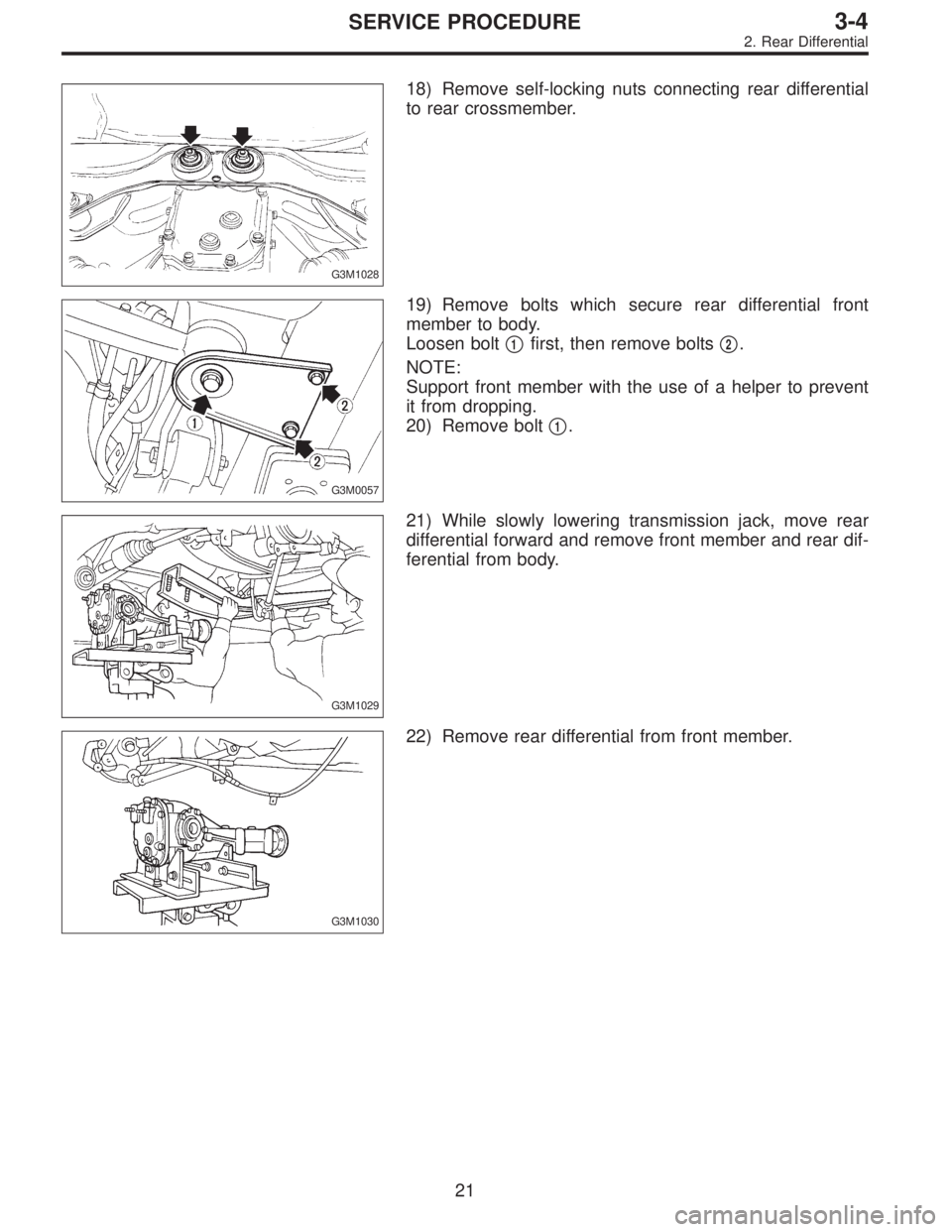
18) Remove self-locking nuts connecting rear differential
to rear crossmember.
G3M0057
19) Remove bolts which secure rear differential front
member to body.
Loosen bolt�
1first, then remove bolts�2.
NOTE:
Support front member with the use of a helper to prevent
it from dropping.
20) Remove bolt�
1.
G3M1029
21) While slowly lowering transmission jack, move rear
differential forward and remove front member and rear dif-
ferential from body.
G3M1030
22) Remove rear differential from front member.
21
3-4SERVICE PROCEDURE
2. Rear Differential
Page 517 of 2248

Symptom and possible cause Remedy
5. Noises when cornering
�
1Damaged differential gear. Replace.
�
2Excessive wear or damage of thrust washer. Replace.
�
3Broken pinion mate shaft. Replace.
�
4Seized or damaged side bearing. Replace.
6. Gear noises
Since noises from engine, muffler, transmission, propeller shaft, wheel bearings, tires, and body are sometimes mistaken for noises
from differential assembly, be careful in checking them. Inspection methods to locate noises include coasting, accelerating, cruising,
and jacking-up all four wheels. Perform these inspections according to condition of trouble. When listening to noises, shift gears into
four wheel drive and fourth speed position, trying to pick up only differential noise.
�
1Improper tooth contact of hypoid gear. Readjust or replace hypoid gear set.
�
2Improper backlash for hypoid gear. Readjust.
�
3Scored or chipped teeth of hypoid gear. Replace hypoid gear set.
�
4Seized hypoid gear. Replace hypoid gear set.
�
5Improper preload for front or rear bearings. Readjust.
�
6Seized, scored, or chipped front or rear bearing. Replace.
�
7Seized, scored, or chipped side bearing. Replace.
�
8Vibrating differential carrier. Replace.
2. Propeller Shaft
Symptom and possible cause Remedy
1. Vibration of propeller shaft
Vibration is caused by propeller shaft during operation and is transferred to vehicle body. Generally vibration increase in proportion to
vehicle speed.
�
1Worn or damaged universal joint. Replace.
�
2Unbalanced propeller shaft due to bend or dent. Replace.
�
3Loose installation of propeller shaft. Retighten.
�
4Worn or damaged center bearing and damaged center mount-
ing rubber.Replace.
2. Tapping when starting and noise while cruising, caused by propeller shaft.
�
1Worn or damaged universal joint. Replace.
�
2Worn spline of sleeve yoke. Replace.
�
3Loose installation of propeller shaft. Retighten.
�
4Loose installation of joint. Replace.
�
5Worn or damaged center bearing and damaged center mount-
ing rubber.Replace.
NOTE:
Vibration while cruising may be caused by an unbalanced
tire, improper tire inflation pressure, improper wheel
alignment, etc.
41
3-4DIAGNOSTICS
1. Rear Differential - 2. Propeller Shaft
Page 518 of 2248

Symptom and possible cause Remedy
5. Noises when cornering
�
1Damaged differential gear. Replace.
�
2Excessive wear or damage of thrust washer. Replace.
�
3Broken pinion mate shaft. Replace.
�
4Seized or damaged side bearing. Replace.
6. Gear noises
Since noises from engine, muffler, transmission, propeller shaft, wheel bearings, tires, and body are sometimes mistaken for noises
from differential assembly, be careful in checking them. Inspection methods to locate noises include coasting, accelerating, cruising,
and jacking-up all four wheels. Perform these inspections according to condition of trouble. When listening to noises, shift gears into
four wheel drive and fourth speed position, trying to pick up only differential noise.
�
1Improper tooth contact of hypoid gear. Readjust or replace hypoid gear set.
�
2Improper backlash for hypoid gear. Readjust.
�
3Scored or chipped teeth of hypoid gear. Replace hypoid gear set.
�
4Seized hypoid gear. Replace hypoid gear set.
�
5Improper preload for front or rear bearings. Readjust.
�
6Seized, scored, or chipped front or rear bearing. Replace.
�
7Seized, scored, or chipped side bearing. Replace.
�
8Vibrating differential carrier. Replace.
2. Propeller Shaft
Symptom and possible cause Remedy
1. Vibration of propeller shaft
Vibration is caused by propeller shaft during operation and is transferred to vehicle body. Generally vibration increase in proportion to
vehicle speed.
�
1Worn or damaged universal joint. Replace.
�
2Unbalanced propeller shaft due to bend or dent. Replace.
�
3Loose installation of propeller shaft. Retighten.
�
4Worn or damaged center bearing and damaged center mount-
ing rubber.Replace.
2. Tapping when starting and noise while cruising, caused by propeller shaft.
�
1Worn or damaged universal joint. Replace.
�
2Worn spline of sleeve yoke. Replace.
�
3Loose installation of propeller shaft. Retighten.
�
4Loose installation of joint. Replace.
�
5Worn or damaged center bearing and damaged center mount-
ing rubber.Replace.
NOTE:
Vibration while cruising may be caused by an unbalanced
tire, improper tire inflation pressure, improper wheel
alignment, etc.
41
3-4DIAGNOSTICS
1. Rear Differential - 2. Propeller Shaft
Page 520 of 2248
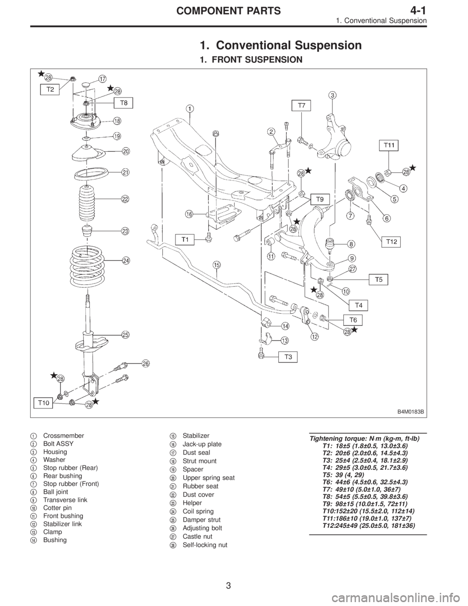
1. Conventional Suspension
1. FRONT SUSPENSION
B4M0183B
�1Crossmember
�
2Bolt ASSY
�
3Housing
�
4Washer
�
5Stop rubber (Rear)
�
6Rear bushing
�
7Stop rubber (Front)
�
8Ball joint
�
9Transverse link
�
10Cotter pin
�
11Front bushing
�
12Stabilizer link
�
13Clamp
�
14Bushing�
15Stabilizer
�
16Jack-up plate
�
17Dust seal
�
18Strut mount
�
19Spacer
�
20Upper spring seat
�
21Rubber seat
�
22Dust cover
�
23Helper
�
24Coil spring
�
25Damper strut
�
26Adjusting bolt
�
27Castle nut
�
28Self-locking nut
Tightening torque: N⋅m (kg-m, ft-lb)
T1: 18±5 (1.8±0.5, 13.0±3.6)
T2: 20±6 (2.0±0.6, 14.5±4.3)
T3: 25±4 (2.5±0.4, 18.1±2.9)
T4: 29±5 (3.0±0.5, 21.7±3.6)
T5: 39 (4, 29)
T6: 44±6 (4.5±0.6, 32.5±4.3)
T7: 49±10 (5.0±1.0, 36±7)
T8: 54±5 (5.5±0.5, 39.8±3.6)
T9: 98±15 (10.0±1.5, 72±11)
T10:152±20 (15.5±2.0, 112±14)
T11:186±10 (19.0±1.0, 137±7)
T12:245±49 (25.0±5.0, 181±36)
3
4-1COMPONENT PARTS
1. Conventional Suspension
Page 532 of 2248
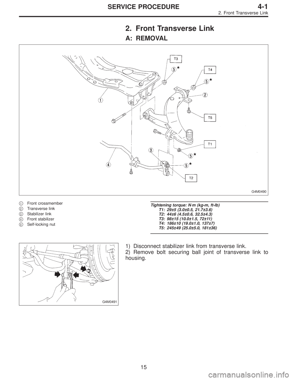
2. Front Transverse Link
A: REMOVAL
G4M0490
�1Front crossmember
�
2Transverse link
�
3Stabilizer link
�
4Front stabilizer
�
5Self-locking nut
Tightening torque: N⋅m (kg-m, ft-lb)
T1: 29±5 (3.0±0.5, 21.7±3.6)
T2: 44±6 (4.5±0.6, 32.5±4.3)
T3: 98±15 (10.0±1.5, 72±11)
T4: 186±10 (19.0±1.0, 137±7)
T5: 245±49 (25.0±5.0, 181±36)
G4M0491
1) Disconnect stabilizer link from transverse link.
2) Remove bolt securing ball joint of transverse link to
housing.
15
4-1SERVICE PROCEDURE
2. Front Transverse Link
Page 533 of 2248
G4M0492
3) Remove nut (do not remove bolt.) securing transverse
link to crossmember.
4) Remove two bolts securing bushing bracket of trans-
verse link to vehicle body at rear bushing location.
G4M0493
5) Extract ball joint from housing.
6) Remove bolt securing transverse link to crossmember
and extract transverse link from crossmember.
G4M0494
B: DISASSEMBLY
1. FRONT BUSHING
Using ST, press front bushing out of place.
ST 927680000 INSTALLER & REMOVER SET
G4M0495
2. REAR BUSHING
1) Scribe an aligning mark on transverse link and rear
bushing.
2) Loosen nut and remove rear bushing.
C: INSPECTION
1) Check transverse link for wear, damage and cracks,
and correct or replace if defective.
2) Check bushings for cracks, wear,damage and creeping.
3) Check rear bushing for oil leaks.
4) If defective, replace with new one.
16
4-1SERVICE PROCEDURE
2. Front Transverse Link
Page 534 of 2248
 Install rear bushing to")
G4M0496
D: ASSEMBLY
1. FRONT BUSHING
To reassemble, reverse disassembly procedures.
CAUTION:
Install front bushing in correct direction, as shown in
figure.
2. REAR BUSHING
1) Install rear bushing to transverse link and align aligning
marks scribed on the two.
2) Tighten self-locking nut.
CAUTION:
�Discard loosened self-locking nut and replace with a
new one.
�While holding rear bushing so as not to change
position of aligning marks, tighten self-locking nut.
Tightening torque:
186±10 N⋅m (19.0±1.0 kg-m, 137±7 ft-lb)
E: INSTALLATION
1) Temporarily tighten the two bolts used to secure rear
bushing of the transverse link to body.
NOTE:
These bolts should be tightened to such an extent that they
can still move back and forth in the oblong shaped hole in
the bracket (which holds the bushing).
2) Install bolts used to connect transverse link to cross-
member and temporarily tighten with nut.
CAUTION:
Discard loosened self-locking nut and replace with a
new one.
3) Insert ball joint into housing.
17
4-1SERVICE PROCEDURE
2. Front Transverse Link
Page 535 of 2248
G4M0497
4) Connect stabilizer link to transverse link, and tempo-
rarily tighten bolts.
CAUTION:
Discard loosened self-locking nut and replace with a
new one.
5) Tighten the following points in the order shown below
when wheels are in full contact with the ground and vehicle
is at curb weight condition.
(1) Transverse link and stabilizer link
Tightening torque:
29±5 N⋅m (3.0±0.5 kg-m, 21.7±3.6 ft-lb)
(2) Transverse link and crossmember
Tightening torque:
98±15 N⋅m (10.0±1.5 kg-m, 72±11 ft-lb)
G4M0928
(3) Transverse link rear bushing and body
Tightening torque:
245±49 N⋅m (25±5 kg-m, 181±36 ft-lb)
NOTE:
�Move rear bushing back and forth until transverse link-
to-rear bushing clearance is established (as indicated in
figure.) before tightening.
�Check wheel alignment and adjust if necessary.
18
4-1SERVICE PROCEDURE
2. Front Transverse Link
 Remove nut (do not remove bolt.) securing transverse
link to crossmember.
4) Remove two bolts securing bushing bracket of trans-
verse link to vehicle body at rear bushing location.
G4M0493")
 Connect stabilizer link to transverse link, and tempo-
rarily tighten bolts.
CAUTION:
Discard loosened self-locking nut and replace with a
new one.
5) Tighten the following points in the or")