Page 1137 of 2248
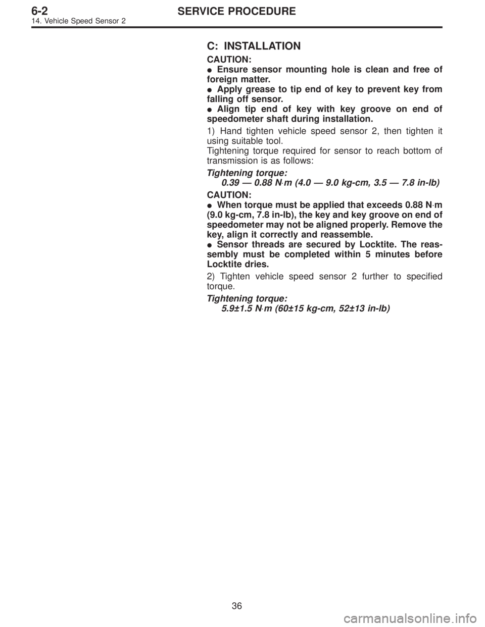
C: INSTALLATION
CAUTION:
�Ensure sensor mounting hole is clean and free of
foreign matter.
�Apply grease to tip end of key to prevent key from
falling off sensor.
�Align tip end of key with key groove on end of
speedometer shaft during installation.
1) Hand tighten vehicle speed sensor 2, then tighten it
using suitable tool.
Tightening torque required for sensor to reach bottom of
transmission is as follows:
Tightening torque:
0.39—0.88 N⋅m (4.0—9.0 kg-cm, 3.5—7.8 in-lb)
CAUTION:
�When torque must be applied that exceeds 0.88 N⋅m
(9.0 kg-cm, 7.8 in-lb), the key and key groove on end of
speedometer may not be aligned properly. Remove the
key, align it correctly and reassemble.
�Sensor threads are secured by Locktite. The reas-
sembly must be completed within 5 minutes before
Locktite dries.
2) Tighten vehicle speed sensor 2 further to specified
torque.
Tightening torque:
5.9±1.5 N⋅m (60±15 kg-cm, 52±13 in-lb)
36
6-2SERVICE PROCEDURE
14. Vehicle Speed Sensor 2
Page 1175 of 2248
 Remove combination meter.
2) Turn ignition switch to ON.
3) Measure voltage at combination meter connector termi-
nal.
Connector & terminal / S")
B6M0530A
1. CHECK POWER SUPPLY FOR COMBINATION
METER.
1) Remove combination meter.
2) Turn ignition switch to ON.
3) Measure voltage at combination meter connector termi-
nal.
Connector & terminal / Specified voltage:
(i14) No. 11—Body / 10 V, or more
B6M0252B
2. CHECK GROUND CIRCUIT OF COMBINATION
METER.
1) Turn ignition switch to OFF.
2) Measure resistance of harness connector between
combination meter and body.
Connector & terminal / Specified voltage:
(i12) No. 1—Body / 10Ω, max.
B6M0294B
3. CHECK HARNESS CONNECTOR BETWEEN
COMBINATION METER AND VEHICLE SPEED
SENSOR 2.
1) Disconnect connector from vehicle speed sensor 2.
2) Measure resistance of harness connector between
vehicle speed sensor 2 and combination meter.
Connector & terminal / Specified resistance:
(B17) No. 1—(i11)No.2/10Ω, max.
(B17) No. 2—(i11)No.3/10Ω, max.
4. CHECK VEHICLE SPEED SENSOR 2.
NOTE:
�If resistance between terminals of vehicle speed sensor
2 is out of specification, the sensor may have a failure.
�If resistance is OK and voltage between terminals of
vehicle speed sensor 2 is out of specification, mechanical
trouble may be present between vehicle speed sensor 2
and speedometer shaft in transmission.
71
6-2DIAGNOSTICS
3. Combination Meter
Page 1211 of 2248

�
2Ignition coil
�
3Ignitor
�
4Crankshaft position sensor
�
5Camshaft position sensor
�
6Throttle position sensor
�
7Fuel injectors
�
8Pressure regulator
�
9Engine coolan")
�1Engine control module (ECM)
�
2Ignition coil
�
3Ignitor
�
4Crankshaft position sensor
�
5Camshaft position sensor
�
6Throttle position sensor
�
7Fuel injectors
�
8Pressure regulator
�
9Engine coolant temperature sensor
�
10Mass air flow sensor
�
11Idle air control solenoid valve
�
12Purge control solenoid valve
�
13Fuel pump
�
14PCV valve
�
15Air cleaner
�
16Canister
�
17Main relay
�
18Fuel pump relay
�
19Fuel filter
�
20Front catalytic converter
�
21Rear catalytic converter
�
22EGR valve�
23EGR control solenoid valve
�
24Radiator fan
�
25Radiator fan relay
�
26Pressure sources switching solenoid valve (AT vehicles only)
�
27Knock sensor
�
28Back-pressure transducer (AT vehicles only)
�
29Front oxygen sensor
�
30Rear oxygen sensor
�
31Pressure sensor (AT vehicles only)
�
32A/C compressor
�
33Inhibitor switch
�
34CHECK ENGINE malfunction indicator lamp (MIL)
�
35Tachometer
�
36A/C relay
�
37A/C control module
�
38Ignition switch
�
39Transmission control module (TCM) (AT vehicles only)
�
40ABS/TCS control module (TCS equipped models)
�
41Vehicle speed sensor
�
42Data link connector (Subaru select monitor)
�
43Data link connector (OBD-II general scan tool)
�
44Two way valve
5
2-7ON-BOARD DIAGNOSTICS II SYSTEM
1. General
Page 1212 of 2248
B: AUTOMATIC TRANSMISSION
1. ELECTRONIC-HYDRAULIC CONTROL SYSTEM
The electronic-hydraulic control system consists of various
sensors and switches, a transmission control module
(TCM) and the hydraulic controller including solenoid
valves. The system controls the transmission proper
including shift control, lock-up control, overrunning clutch
control, line pressure control and shift timing control. It also
controls the AWD transfer clutch. In other words, the sys-
tem detects various operating conditions from various input
signals and sends output signals to shift solenoids 1, 2 and
3 and duty solenoids A, B and C (a total of six solenoids).
6
2-7ON-BOARD DIAGNOSTICS II SYSTEM
1. General
Page 1227 of 2248
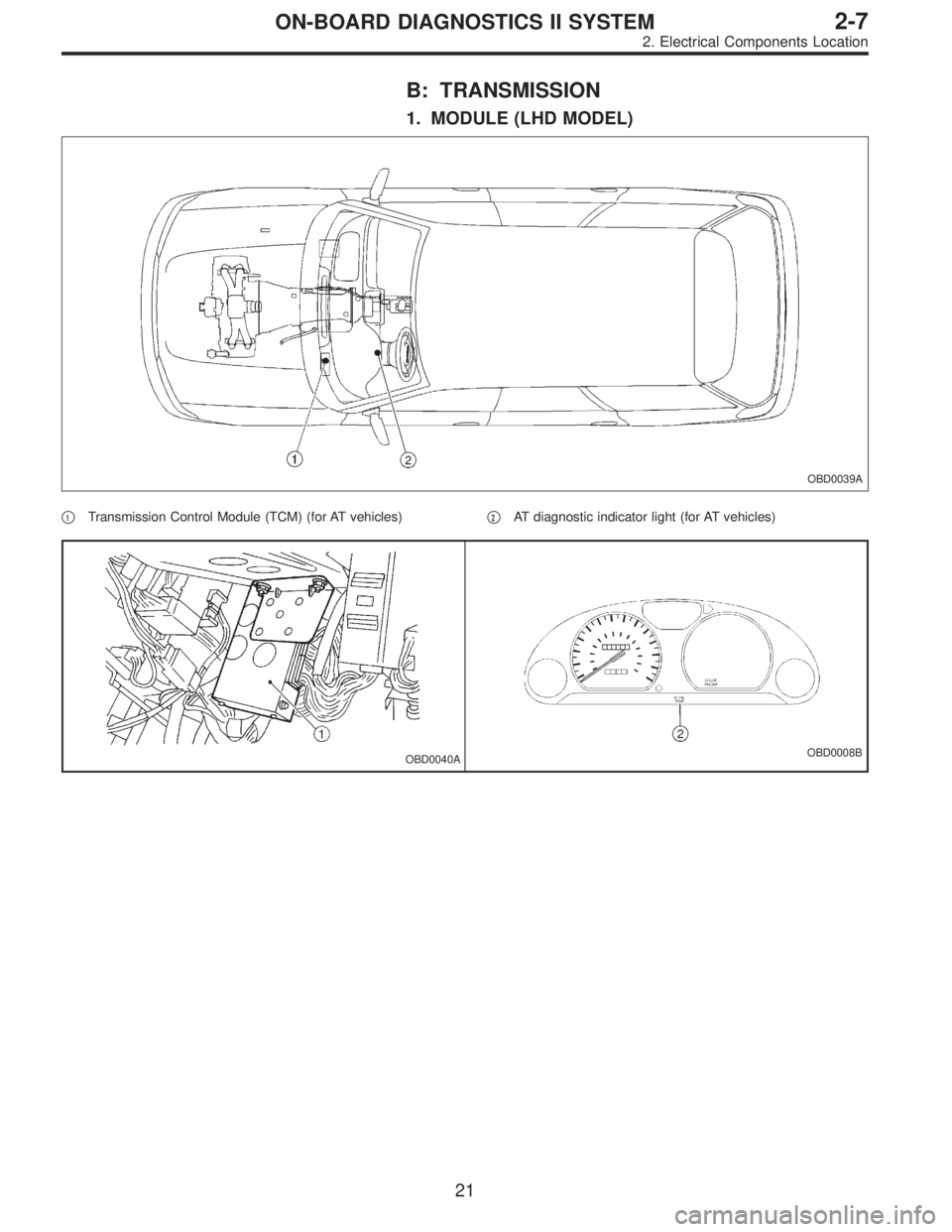
B: TRANSMISSION
1. MODULE (LHD MODEL)
OBD0039A
�1Transmission Control Module (TCM) (for AT vehicles)�2AT diagnostic indicator light (for AT vehicles)
OBD0040AOBD0008B
21
2-7ON-BOARD DIAGNOSTICS II SYSTEM
2. Electrical Components Location
Page 1228 of 2248
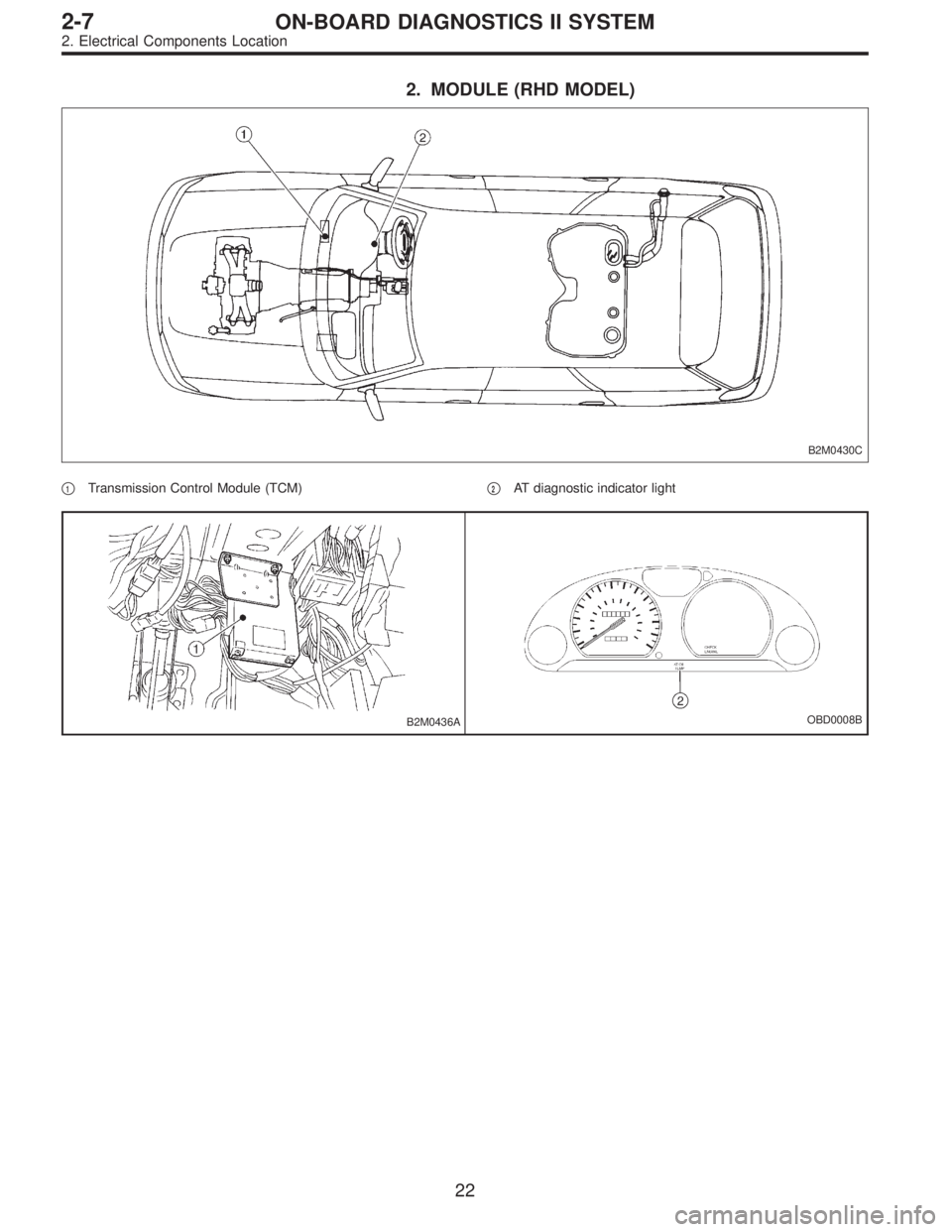
2. MODULE (RHD MODEL)
B2M0430C
�1Transmission Control Module (TCM)�2AT diagnostic indicator light
B2M0436AOBD0008B
22
2-7ON-BOARD DIAGNOSTICS II SYSTEM
2. Electrical Components Location
Page 1271 of 2248
, main relay and fuel pump relay.
CAUTION:
�All Airbag system wirin")
4. Cautions
A: SUPPLEMENTAL RESTRAINT SYSTEM
“AIRBAG”
Airbag system wiring harness is routed near the engine
control module (ECM), main relay and fuel pump relay.
CAUTION:
�All Airbag system wiring harness and connectors
are colored yellow. Do not use electrical test equip-
ment on these circuit.
�Be careful not to damage Airbag system wiring har-
ness when servicing the engine control module (ECM),
transmission control module (TCM), main relay and
fuel pump relay.
B: PRECAUTIONS
1) Never connect the battery in reverse polarity.
�The ECM will be destroyed instantly.
�The fuel injector and other part will be damaged in just
a few minutes more.
2) Do not disconnect the battery terminals while the
engine is running.
�A large counter electromotive force will be generated in
the alternator, and this voltage may damage electronic
parts such as ECM, etc.
3) Before disconnecting the connectors of each sensor
and the ECM, be sure to turn OFF the ignition switch.
4) Before removing ECM from the located position, dis-
connect two cables on battery.
�Otherwise, the ECM may be damaged.
5) The connectors to each sensor in the engine compart-
ment and the harness connectors on the engine side and
body side are all designed to be waterproof. However, it is
still necessary to take care not to allow water to get into the
connectors when washing the vehicle, or when servicing
the vehicle on a rainy day.
6) Every MFI-related part is a precision part. Do not drop
them.
7) Observe the following cautions when installing a radio
in MFI equipped models.
CAUTION:
�The antenna must be kept as far apart as possible
from the control unit.
(The ECM is located under the steering column, inside
of the instrument panel lower trim panel.)
�The antenna feeder must be placed as far apart as
possible from the ECM and MFI harness.
�Carefully adjust the antenna for correct matching.
65
2-7ON-BOARD DIAGNOSTICS II SYSTEM
4. Cautions
Page 1272 of 2248
 Before disconnecting t")
�When mounting a large power type radio, pay spe-
cial attention to the three items above mentioned.
�Incorrect installation of the radio may affect the
operation of the ECM.
8) Before disconnecting the fuel hose, disconnect the fuel
pump connector and crank the engine for more than five
seconds to release pressure in the fuel system. If engine
starts during this operation, run it until it stops.
9) Problems in the electronic-controlled automatic trans-
mission may be caused by failure of the engine, the elec-
tronic control system, the transmission proper, or by a com-
bination of these. These three causes must be distin-
guished clearly when performing diagnostics.
10) Diagnostics should be conducted by rotating with
simple, easy operations and proceeding to complicated,
difficult operations. The most important thing in diagnostics
is to understand the customer’s complaint, and distinguish
between the three causes.
11) In AT vehicles, do not continue the stall for more than
five seconds at a time (from closed throttle, fully open
throttle to stall engine speed).
12) On ABS or ABS/TCS vehicle, when performing driving
test in jacked-up or lifted-up position, sometimes the warn-
ing light may be lit, but this is not a malfunction of the sys-
tem. The reason for this is the speed difference between
the front and rear wheels. After diagnosis of engine control
system, perform the ABS or ABS/TCS memory clearance
procedure of self-diagnosis system.
4-4b [T6C2] or [T9K0].>
C: PRE-INSPECTION
Before performing diagnostics, check the following items
which might affect engine problems:
1. POWER SUPPLY
1) Measure battery voltage and specific gravity of electro-
lyte.
Standard voltage: 12 V
Specific gravity: Above 1.260
2) Check the condition of the main and other fuses, and
harnesses and connectors. Also check for proper ground-
ing.
OBD0091A
2. ENGINE GROUNDING
Make sure the engine grounding terminal is properly con-
nected to the engine.
66
2-7ON-BOARD DIAGNOSTICS II SYSTEM
4. Cautions
 and the hydraulic")