Page 1337 of 2248

Problem parts
Inhibitor switch
Control module
Vehicle speed sensor 1
Vehicle speed sensor 2
Select cable
Select lever
FWD switch
Starter motor and harness
Throttle position sensor
Hold switch
Accumulator (“N”—“D”)
Accumulator (2A)
Accumulator (4A)
Accumulator (3R)
ATF temperature sensor
Strainer
Duty solenoid A
Duty solenoid B
Shift solenoid 1
Shift solenoid 2
Shift solenoid 3
Control valve
Detent spring
Manual plate
Transfer clutch
Transfer valve
Transfer pipe
Duty solenoid C
Forward clutch
Symptom1234567891011121314151617181920212223242526272829
Engine brake is not effected when select
lever is in“3”or“2”range.
Engine brake is not effected when select
lever is in“1”range.�
Shift characteristics are erroneous.���� � �
No lock-up occurs.����
Vehicle cannot be set in“D”range power
mode.��
“D”range power mode cannot be released.���
Parking brake is not effected.��
Shift lever cannot be moved or is hard to
move from“P”range.��
Select lever is hard to move.�� ��
Select lever is too light to move (unreason-
able resistance).��
ATF spurts out.
Differential oil spurts out.
Differential oil level changes excessively.
Odor is produced from oil supply pipe.��
Shock occurs when select lever is moved
from“1”to“2”range.� ���� �
Slippage occurs when select lever is moved
from“1”to“2”range.� ���� �
Shock occurs when select lever is moved
from“2”to“3”range.������
Slippage occurs when select lever is moved
from“2”to“3”range.������
Shock occurs when select lever is moved
from“3”to“4”range.� � ��� �
Slippage occurs when select lever is moved
from“3”to“4”range.� � ��� �
Shock occurs when select lever is moved
from“3”to“2”range.�����
Shock occurs when select lever is moved
from“D”to“1”range.�����
Shock occurs when select lever is moved
from“2”to“1”range.�����
Shock occurs when accelerator pedal is
released at medium speeds.�����
Vibration occurs during straight-forward
operation.��
Select lever slips out of position during
acceleration or while driving on rough terrain.�� ��
Vibration occurs during turns (tight corner
“braking”phenomenon).��� �� � �� �
Front wheel slippage occurs during standing
starts.� � � �� � � ����
Vehicle is not set in FWD mode.�� ���
1234567891011121314151617181920212223242526272829
131
2-7ON-BOARD DIAGNOSTICS II SYSTEM
10. General Diagnostics Table
Page 1340 of 2248
Item Page
P0705 RNG Transmission range sensor circuit malfunction 274
P0710 ATF Transmission fluid temperature sensor circuit malfunction 279
P0720 ATVSP Out")
DTC
No.Abbreviation
(Subaru select monitor)Item Page
P0705 RNG Transmission range sensor circuit malfunction 274
P0710 ATF Transmission fluid temperature sensor circuit malfunction 279
P0720 ATVSP Output speed sensor (vehicle speed sensor 1) circuit malfunction 281
P0725 ATNE Engine speed input circuit malfunction 283
P0731 GR
—1 Gear 1 incorrect ratio
285 P0732 GR
—2 Gear 2 incorrect ratio
P0733 GR
—3 Gear 3 incorrect ratio
P0734 GR
—4 Gear 4 incorrect ratio
P0740 LU
—F Torque converter clutch system malfunction 289
P0743 LU Torque converter clutch system electrical 294
P0748 PL Pressure control solenoid electrical 296
P0753 SFT1 Shift solenoid A electrical 298
P0758 SFT2 Shift solenoid B electrical 300
P0760 OVR
—F Shift solenoid C malfunction 302
P0763 OVR Shift solenoid C electrical 307
P1100 ST
—SW Starter switch circuit malfunction 309
P1101 N
—SW Neutral position switch circuit malfunction [MT vehicles] 311
P1101 N
—SW Neutral position switch circuit malfunction [AT vehicles] 315
P1102 BR Pressure sources switching solenoid valve circuit malfunction 319
P1103 TRQ Engine torque control signal circuit malfunction 325
P1104 TCS TCS signal circuit malfunction 328
P1500 FAN
—1 Radiator fan relay 1 circuit malfunction 331
P1502 FAN
—F Radiator fan function problem 338
P1700 ATTH Throttle position sensor circuit malfunction for automatic transmission 341
P1701 CRS Cruise control set signal circuit malfunction for automatic transmission 343
P1702 ATDIAG Automatic transmission diagnosis input signal circuit malfunction 346
134
2-7ON-BOARD DIAGNOSTICS II SYSTEM
11. Diagnostics Chart with Trouble Code
Page 1341 of 2248
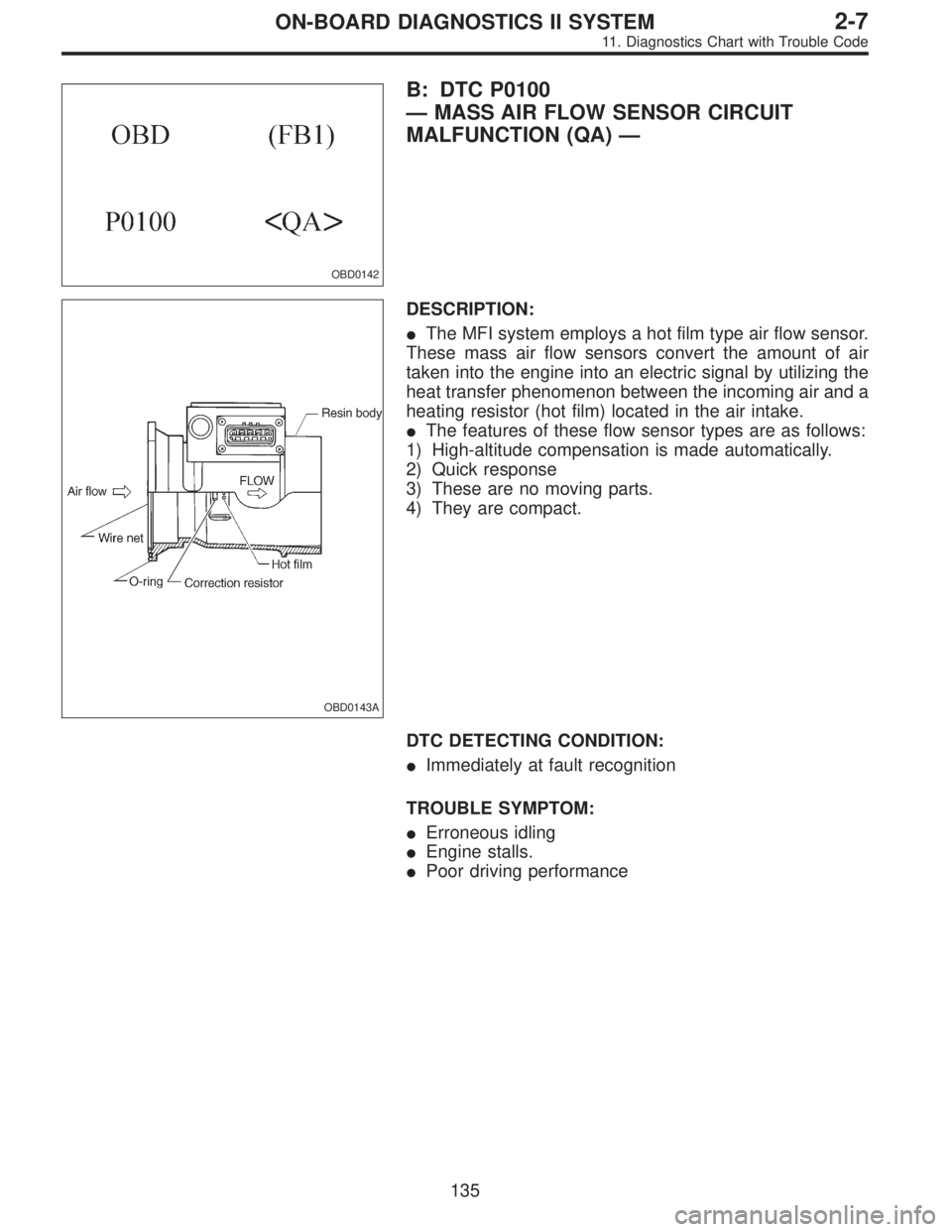
OBD0142
B: DTC P0100
—MASS AIR FLOW SENSOR CIRCUIT
MALFUNCTION (QA)—
OBD0143A
DESCRIPTION:
�The MFI system employs a hot film type air flow sensor.
These mass air flow sensors convert the amount of air
taken into the engine into an electric signal by utilizing the
heat transfer phenomenon between the incoming air and a
heating resistor (hot film) located in the air intake.
�The features of these flow sensor types are as follows:
1) High-altitude compensation is made automatically.
2) Quick response
3) These are no moving parts.
4) They are compact.
DTC DETECTING CONDITION:
�Immediately at fault recognition
TROUBLE SYMPTOM:
�Erroneous idling
�Engine stalls.
�Poor driving performance
135
2-7ON-BOARD DIAGNOSTICS II SYSTEM
11. Diagnostics Chart with Trouble Code
Page 1351 of 2248
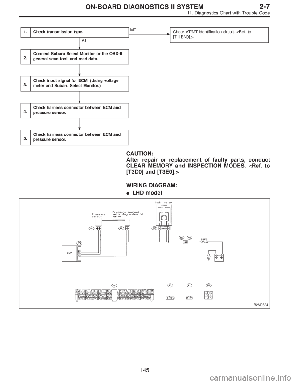
1.Check transmission type.
AT
�MT
Check AT/MT identification circuit.
[T11BN0].>
2.Connect Subaru Select Monitor or the OBD-II
general scan tool, and read data.
3.Check input signal for ECM. (Using voltage
meter and Subaru Select Monitor.)
4.Check harness connector between ECM and
pressure sensor.
5.Check harness connector between ECM and
pressure sensor.
CAUTION:
After repair or replacement of faulty parts, conduct
CLEAR MEMORY and INSPECTION MODES.
[T3D0] and [T3E0].>
WIRING DIAGRAM:
�LHD model
B2M0624
�
�
�
�
145
2-7ON-BOARD DIAGNOSTICS II SYSTEM
11. Diagnostics Chart with Trouble Code
Page 1353 of 2248
 Turn ignition switch to OFF.")
1
CHECK TRANSMISSION TYPE.
Refer to the flow chart on page 145.
OBD0145A
OBD0620
OBD0641
2CONNECT SUBARU SELECT MONITOR OR
THE OBD-II GENERAL SCAN TOOL, AND
READ DATA.
1) Turn ignition switch to OFF.
2) Connect Subaru Select Monitor or the OBD-II general
scan tool to data link connector.
3) Turn ignition switch to ON and Subaru Select Monitor or
the OBD-II general scan tool switch to ON.
4) Start engine.
5) Read the data on Subaru Select Monitor or the OBD-II
general scan tool.
�Subaru Select Monitor
Designate mode using function key.
Function mode: F24 or F49
�F24: Display shows voltage signal value sent from pres-
sure sensor.
�F49: Display shows pressure signal value sent from
pressure sensor.
: Less than 0.2 V or 0 kPa
: Go to step 3.
: Go to next.
: More than 4.9 V or 140 kPa
: Go to step 5.
: Repair the harness and connector between pres-
sure sensor and ECM.
HINT:�
1Open or short circuit of harness between pres-
sure sensor and ECM.
�
2Poor contact of pressure sensor connector and
ECM connector.
�OBD-II general scan tool
For detailed operation procedures, refer to the OBD-II Gen-
eral Scan Tool Instruction Manual.
147
2-7ON-BOARD DIAGNOSTICS II SYSTEM
11. Diagnostics Chart with Trouble Code
Page 1357 of 2248
OBD0170
E: DTC P0106
—PRESSURE SENSOR CIRCUIT
RANGE/PERFORMANCE PROBLEM (P
—R)—
DESCRIPTION:
Refer to“D: DTC P0105—PRESSURE SENSOR CIR-
CUIT MALFUNCTION—[T11D0]”.
DTC DETECTING CONDITION:
�Two consecutive trips with fault
1.Check transmission type.
AT
�MT
Check AT/MT identification circuit.
2.Check DTC P0105 or P1102 on display.
No
�Ye s
�Inspect DTC P0105 or P1102 using“11. Diagnostics
Chart with Trouble Code [T1100]”.
�In this case, it is unnecessary to inspect DTC
P0106.
3.Check data for control.
4.Check vacuum hose.
5.Check pressure sources of switching solenoid
valve.
CAUTION:
After repair or replacement of faulty parts, conduct
CLEAR MEMORY and INSPECTION MODES.
[T3D0] and [T3E0].>
�
�
�
�
151
2-7ON-BOARD DIAGNOSTICS II SYSTEM
11. Diagnostics Chart with Trouble Code
Page 1359 of 2248
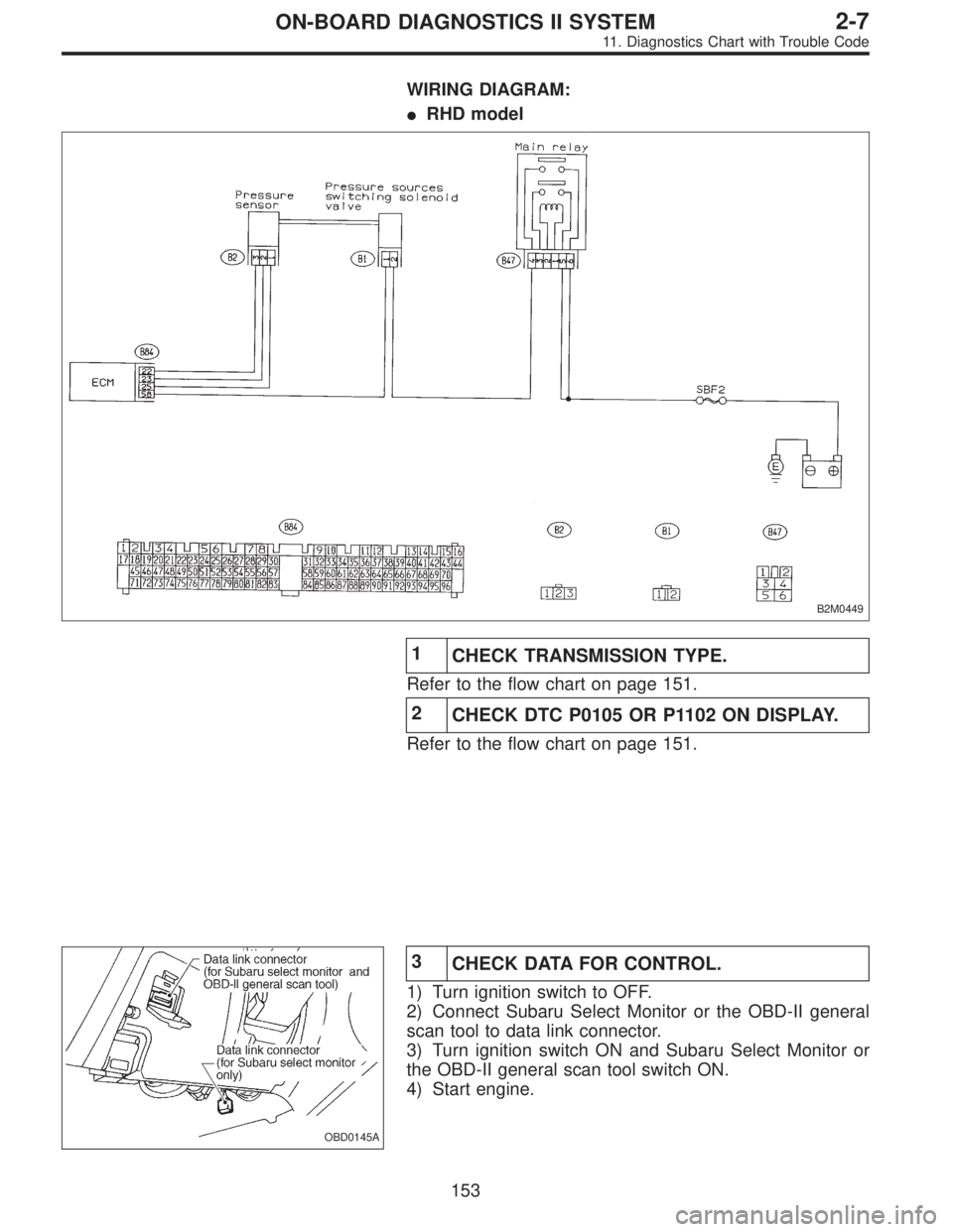
WIRING DIAGRAM:
�RHD model
B2M0449
1
CHECK TRANSMISSION TYPE.
Refer to the flow chart on page 151.
2
CHECK DTC P0105 OR P1102 ON DISPLAY.
Refer to the flow chart on page 151.
OBD0145A
3
CHECK DATA FOR CONTROL.
1) Turn ignition switch to OFF.
2) Connect Subaru Select Monitor or the OBD-II general
scan tool to data link connector.
3) Turn ignition switch ON and Subaru Select Monitor or
the OBD-II general scan tool switch ON.
4) Start engine.
153
2-7ON-BOARD DIAGNOSTICS II SYSTEM
11. Diagnostics Chart with Trouble Code
Page 1362 of 2248
OBD0172
F: DTC P0115
—ENGINE COOLANT TEMPERATURE
SENSOR CIRCUIT MALFUNCTION (TW)—
OBD0173A
DESCRIPTION:
The engine coolant temperature sensor is located on the
engine coolant pipe which is made of aluminum alloy. Its
thermistor changes resistance with respect to temperature.
A engine coolant temperature signal converted into resis-
tance is transmitted to the ECM to control the amount of
fuel injection, ignition timing, purge control solenoid valve,
etc.
DTC DETECTING CONDITION:
�Immediately at fault recognition
TROUBLE SYMPTOM:
�Hard to start
�Erroneous idling
�Poor driving performance
156
2-7ON-BOARD DIAGNOSTICS II SYSTEM
11. Diagnostics Chart with Trouble Code
![SUBARU LEGACY 1995 Service Repair Manual OBD0170
E: DTC P0106
—PRESSURE SENSOR CIRCUIT
RANGE/PERFORMANCE PROBLEM (P
—R)—
DESCRIPTION:
Refer to“D: DTC P0105—PRESSURE SENSOR CIR-
CUIT MALFUNCTION—[T11D0]”.
DTC DETECTING CONDITION](/manual-img/17/57432/w960_57432-1356.png "SUBARU LEGACY 1995 Service Repair Manual OBD0170
E: DTC P0106
—PRESSURE SENSOR CIRCUIT
RANGE/PERFORMANCE PROBLEM (P
—R)—
DESCRIPTION:
Refer to“D: DTC P0105—PRESSURE SENSOR CIR-
CUIT MALFUNCTION—[T11D0]”.
DTC DETECTING CONDITION")
—
OBD0173A
DESCRIPTION:
The engine coolant temperature sensor is located on the
engine coolant pipe which is made of")