Page 1277 of 2248

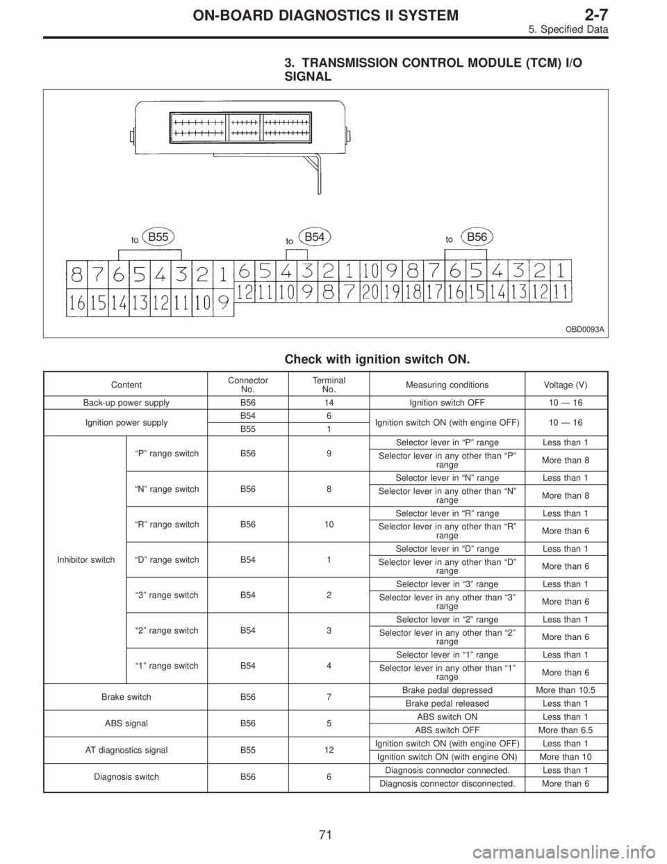
3. TRANSMISSION CONTROL MODULE (TCM) I/O
SIGNAL
OBD0093A
Check with ignition switch ON.
ContentConnector
No.Terminal
No.Measuring conditions Voltage (V)
Back-up power supply B56 14 Ignition switch OFF 10—16
Ignition power supplyB54 6
Ignition switch ON (with engine OFF) 10—16
B55 1
Inhibitor switch“P”range switch B56 9Selector lever in“P”range Less than 1
Selector lever in any other than“P”
rangeMore than 8
“N”range switch B56 8Selector lever in“N”range Less than 1
Selector lever in any other than“N”
rangeMore than 8
“R”range switch B56 10Selector lever in“R”range Less than 1
Selector lever in any other than“R”
rangeMore than 6
“D”range switch B54 1Selector lever in“D”range Less than 1
Selector lever in any other than“D”
rangeMore than 6
“3”range switch B54 2Selector lever in“3”range Less than 1
Selector lever in any other than“3”
rangeMore than 6
“2”range switch B54 3Selector lever in“2”range Less than 1
Selector lever in any other than“2”
rangeMore than 6
“1”range switch B54 4Selector lever in“1”range Less than 1
Selector lever in any other than“1”
rangeMore than 6
Brake switch B56 7Brake pedal depressed More than 10.5
Brake pedal released Less than 1
ABS signal B56 5ABS switch ON Less than 1
ABS switch OFF More than 6.5
AT diagnostics signal B55 12Ignition switch ON (with engine OFF) Less than 1
Ignition switch ON (with engine ON) More than 10
Diagnosis switch B56 6Diagnosis connector connected. Less than 1
Diagnosis connector disconnected. More than 6
71
2-7ON-BOARD DIAGNOSTICS II SYSTEM
5. Specified Data
Page 1291 of 2248
B: ELECTRICAL WIRING HARNESS AND
GROUND POINT
B6M0267A
�1Front wiring harness
�
2Engine wiring harness
�
3Room light cord
�
4Bulkhead wiring harness
�
5Instrument panel wiring harness
�
6Front door cord RH
�
7Rear door cord RH
�
8Rear wiring harness
�
9Trunk lid cord (Sedan)�
10Rear defogger ground cord (Sedan)
�
11Fuel tank cord
�
12Rear door cord LH
�
13Front door cord LH
�
14Sunroof cord
�
15Floor wiring harness
�
16Transmission cord
�
17Rear gate cord (Wagon)
�
18Rear oxygen sensor cord
85
2-7ON-BOARD DIAGNOSTICS II SYSTEM
6. Wiring Diagram and Wiring Harness
Page 1296 of 2248
5. ENGINE WIRING HARNESS, TRANSMISSION
HARNESS AND GROUND POINT (LHD MODEL)
OBD0731
90
2-7ON-BOARD DIAGNOSTICS II SYSTEM
6. Wiring Diagram and Wiring Harness
Page 1297 of 2248
6. ENGINE WIRING HARNESS, TRANSMISSION
HARNESS AND GROUND POINT (RHD MODEL)
B2M0440
91
2-7ON-BOARD DIAGNOSTICS II SYSTEM
6. Wiring Diagram and Wiring Harness
Page 1306 of 2248
![SUBARU LEGACY 1995 Service Repair Manual 7. Basic Diagnostics Procedure
Trouble occurs.
Ask the customer when and how the
trouble occurred using interview
check list. <Ref. to [T702].>
Start the engine.
Ye s�NoInspection using“9. Diagnosti SUBARU LEGACY 1995 Service Repair Manual 7. Basic Diagnostics Procedure
Trouble occurs.
Ask the customer when and how the
trouble occurred using interview
check list. <Ref. to [T702].>
Start the engine.
Ye s�NoInspection using“9. Diagnosti](/manual-img/17/57432/w960_57432-1305.png)
7. Basic Diagnostics Procedure
Trouble occurs.
Ask the customer when and how the
trouble occurred using interview
check list.
Start the engine.
Ye s�NoInspection using“9. Diagnostics for
Engine Start Failure [T900]”
Malfunction indicator lamp (MIL) illu-
minates.
Ye s�NoInspection using“10. General Diag-
nostics Table [T1000]”
Inspection using Subaru select moni-
tor or OBD-II general scan tool.
(Subaru select monitor: MODE FB1)
Trouble code
�No trouble code designated.Repair.
See NOTE: *1
designated.
Inspection using“11. Diagnostics
Chart with Trouble Code [T11A0]”.
See NOTE: *2.
�Trouble code
designated.
�
Repair.
Inspection mode
Inspection using Subaru select moni-
tor or OBD-II general scan tool.
(Subaru select monitor: MODE FB0)
No trouble code
�Clear memory mode.�
designated.
END
NOTE:
*1: If trouble code is not shown on display although the
MIL illuminates, perform diagnostics of the MIL (CHECK
ENGINE LIGHT) circuit or combination meter.
Diagnostics for CHECK ENGINE Malfunction Indicator
Lamp (MIL) [T800].”>
*2: Carry out the basic check, only when trouble code
about automatic transmission is shown on display.
[T701].>
�
�
�
�
�
�
100
2-7ON-BOARD DIAGNOSTICS II SYSTEM
7. Basic Diagnostics Procedure
Page 1307 of 2248
1. BASIC CHECK ITEMS FOR AT
When trouble code about automatic transmission is shown
on display, carry out the following basic check. After that,
carry out the replacement or repair work.
1) ATF level check
2) Differential gear oil level check
3) ATF leak check
4) Differential gear oil leak check
5) Brake band adjustment
6) Stall test
7) Line pressure test
8) Transfer clutch pressure test
9) Time lag test
10) Road test
11) Shift characteristics
NOTE:
As for the method, refer to 3-2 [W2A1].
101
2-7ON-BOARD DIAGNOSTICS II SYSTEM
7. Basic Diagnostics Procedure
Page 1316 of 2248

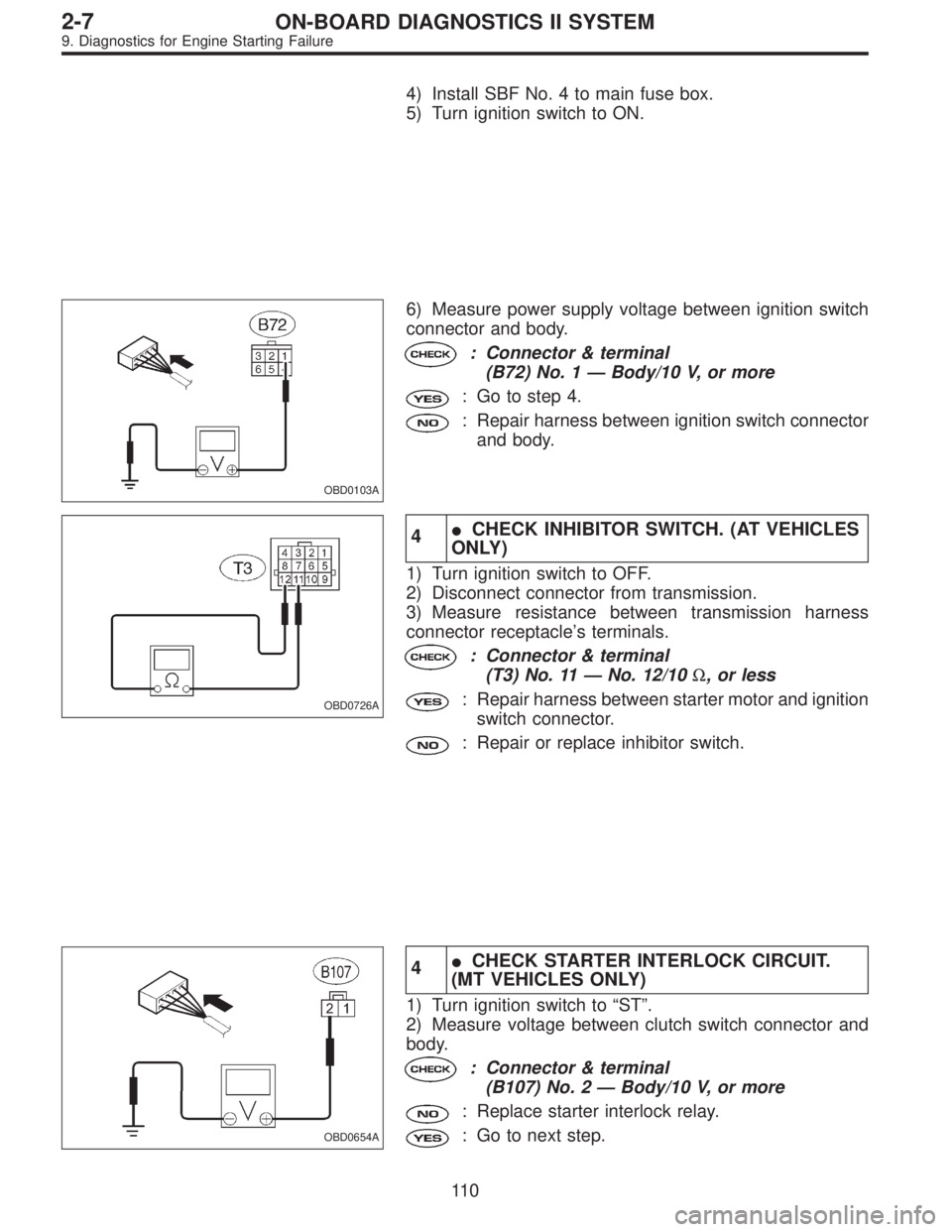
4) Install SBF No. 4 to main fuse box.
5) Turn ignition switch to ON.
OBD0103A
6) Measure power supply voltage between ignition switch
connector and body.
: Connector & terminal
(B72) No. 1—Body/10 V, or more
: Go to step 4.
: Repair harness between ignition switch connector
and body.
OBD0726A
4�CHECK INHIBITOR SWITCH. (AT VEHICLES
ONLY)
1) Turn ignition switch to OFF.
2) Disconnect connector from transmission.
3) Measure resistance between transmission harness
connector receptacle’s terminals.
: Connector & terminal
(T3) No. 11—No. 12/10Ω, or less
: Repair harness between starter motor and ignition
switch connector.
: Repair or replace inhibitor switch.
OBD0654A
4�CHECK STARTER INTERLOCK CIRCUIT.
(MT VEHICLES ONLY)
1) Turn ignition switch to“ST”.
2) Measure voltage between clutch switch connector and
body.
: Connector & terminal
(B107) No. 2—Body/10 V, or more
: Replace starter interlock relay.
: Go to next step.
11 0
2-7ON-BOARD DIAGNOSTICS II SYSTEM
9. Diagnostics for Engine Starting Failure
Page 1335 of 2248

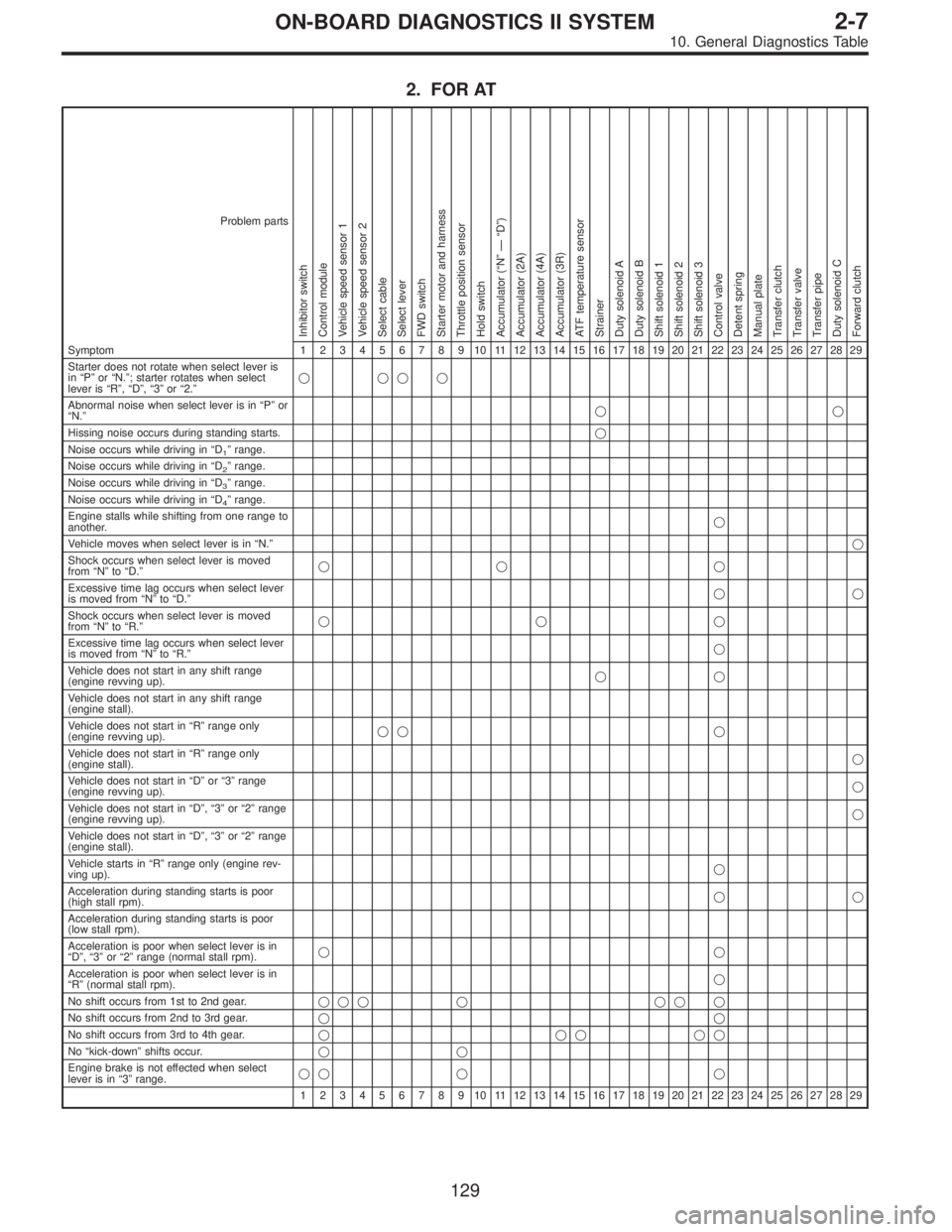
2. FOR AT
Problem parts
Inhibitor switch
Control module
Vehicle speed sensor 1
Vehicle speed sensor 2
Select cable
Select lever
FWD switch
Starter motor and harness
Throttle position sensor
Hold switch
Accumulator (“N”—“D”)
Accumulator (2A)
Accumulator (4A)
Accumulator (3R)
ATF temperature sensor
Strainer
Duty solenoid A
Duty solenoid B
Shift solenoid 1
Shift solenoid 2
Shift solenoid 3
Control valve
Detent spring
Manual plate
Transfer clutch
Transfer valve
Transfer pipe
Duty solenoid C
Forward clutch
Symptom1234567891011121314151617181920212223242526272829
Starter does not rotate when select lever is
in“P”or“N.”; starter rotates when select
lever is“R”,“D”,“3”or“2.”����
Abnormal noise when select lever is in“P”or
“N.”��
Hissing noise occurs during standing starts.�
Noise occurs while driving in“D
1”range.
Noise occurs while driving in“D
2”range.
Noise occurs while driving in“D
3”range.
Noise occurs while driving in“D
4”range.
Engine stalls while shifting from one range to
another.�
Vehicle moves when select lever is in“N.”�
Shock occurs when select lever is moved
from“N”to“D.”�� �
Excessive time lag occurs when select lever
is moved from“N”to“D.”��
Shock occurs when select lever is moved
from“N”to“R.”���
Excessive time lag occurs when select lever
is moved from“N”to“R.”�
Vehicle does not start in any shift range
(engine revving up).��
Vehicle does not start in any shift range
(engine stall).
Vehicle does not start in“R”range only
(engine revving up).�� �
Vehicle does not start in“R”range only
(engine stall).�
Vehicle does not start in“D”or“3”range
(engine revving up).�
Vehicle does not start in“D”,“3”or“2”range
(engine revving up).�
Vehicle does not start in“D”,“3”or“2”range
(engine stall).
Vehicle starts in“R”range only (engine rev-
ving up).�
Acceleration during standing starts is poor
(high stall rpm).��
Acceleration during standing starts is poor
(low stall rpm).
Acceleration is poor when select lever is in
“D”,“3”or“2”range (normal stall rpm).��
Acceleration is poor when select lever is in
“R”(normal stall rpm).�
No shift occurs from 1st to 2nd gear.��� � �� �
No shift occurs from 2nd to 3rd gear.��
No shift occurs from 3rd to 4th gear.�����
No“kick-down”shifts occur.��
Engine brake is not effected when select
lever is in“3”range.�� � �
1234567891011121314151617181920212223242526272829
129
2-7ON-BOARD DIAGNOSTICS II SYSTEM
10. General Diagnostics Table