Page 1487 of 2248
![SUBARU LEGACY 1995 Service Repair Manual OBD0392
AP: DTC P0720
—OUTPUT SPEED SENSOR (VEHICLE
SPEED SENSOR 1) CIRCUIT MALFUNCTION
(ATVSP)—
OBD0393A
DESCRIPTION:
[FWD model]
�The vehicle speed sensor 1 is mounted to the transmis-
sion case SUBARU LEGACY 1995 Service Repair Manual OBD0392
AP: DTC P0720
—OUTPUT SPEED SENSOR (VEHICLE
SPEED SENSOR 1) CIRCUIT MALFUNCTION
(ATVSP)—
OBD0393A
DESCRIPTION:
[FWD model]
�The vehicle speed sensor 1 is mounted to the transmis-
sion case](/manual-img/17/57432/w960_57432-1486.png)
OBD0392
AP: DTC P0720
—OUTPUT SPEED SENSOR (VEHICLE
SPEED SENSOR 1) CIRCUIT MALFUNCTION
(ATVSP)—
OBD0393A
DESCRIPTION:
[FWD model]
�The vehicle speed sensor 1 is mounted to the transmis-
sion case (at the rear side of the case). The sensor outputs
a pulse signal which is transmission to the TCM where it is
converted to vehicle speed.
�Vehicle speed sensor 1 on FWD model detects front-
wheel speed.
OBD0394A
[AWD]
�The vehicle speed sensor 1 (output shaft rotation sen-
sor) is mounted to the extension case (from the outside of
the case). The sensor outputs a pulse signal which is trans-
mitted to the TCM where it is converted to vehicle speed.
�The transfer clutch drum is connected directly to the rear
wheel driving propeller shaft. Vehicle speed sensor 1 on
the AWD model defects rear-wheel speed.
DTC DETECTING CONDITION:
�Two consecutive trips with fault
TROUBLE SYMPTOM:
�No shift or excessive tight corner“braking”
281
2-7ON-BOARD DIAGNOSTICS II SYSTEM
11. Diagnostics Chart with Trouble Code
Page 1494 of 2248
2CHECK THROTTLE POSITION SENSOR CIR-
CUIT.
: Is there any trouble in throttle position sen-
sor circuit?
: Repair or replace throttle position sensor circuit.
: Go to step 3.
3
CHECK VEHICLE SPEED SENSOR 1 CIRCUIT.
: Is there any trouble in vehicle speed sensor
1 circuit?
: Repair or replace vehicle speed sensor 1 circuit.
: Go to step 4.
4
CHECK VEHICLE SPEED SENSOR 2 CIRCUIT.
: Is there any trouble in vehicle speed sensor
2 circuit?
: Repair or replace vehicle speed sensor 2 circuit.
: Go to step 5.
5
CHECK ENGINE SPEED INPUT CIRCUIT.
: Is there any trouble in engine speed input
circuit?
: Repair or replace engine speed input circuit.
: Go to next.
: Is there poor contact in TCM connector?
: Repair poor contact in TCM connector.
: Go to next.
: Is there any mechanical trouble in automatic
transmission?
: Repair or replace automatic transmission.
: Replace TCM with a new one.
288
2-7ON-BOARD DIAGNOSTICS II SYSTEM
11. Diagnostics Chart with Trouble Code
Page 1499 of 2248
7
CHECK INHIBITOR SWITCH CIRCUIT.
: Is there any trouble in inhibitor switch cir-
cuit?
: Repair or replace inhibitor switch circuit.
: Go to step 8.
8
CHECK BRAKE LIGHT SWITCH CIRCUIT.
: Is there any trouble in brake light switch cir-
cuit?
: Repair or replace brake light switch circuit.
: Go to step 9.
9CHECK ATF TEMPERATURE SENSOR CIR-
CUIT.
: Is there any trouble in ATF temperature sen-
sor circuit?
: Repair or replace ATF temperature sensor circuit.
: Go to next.
: Is there poor contact in TCM connector?
: Repair poor contact in TCM connector.
: Go to next.
: Is there any mechanical trouble in automatic
transmission?
: Repair or replace automatic transmission.
: Replace TCM with a new one.
293
2-7ON-BOARD DIAGNOSTICS II SYSTEM
11. Diagnostics Chart with Trouble Code
Page 1511 of 2248

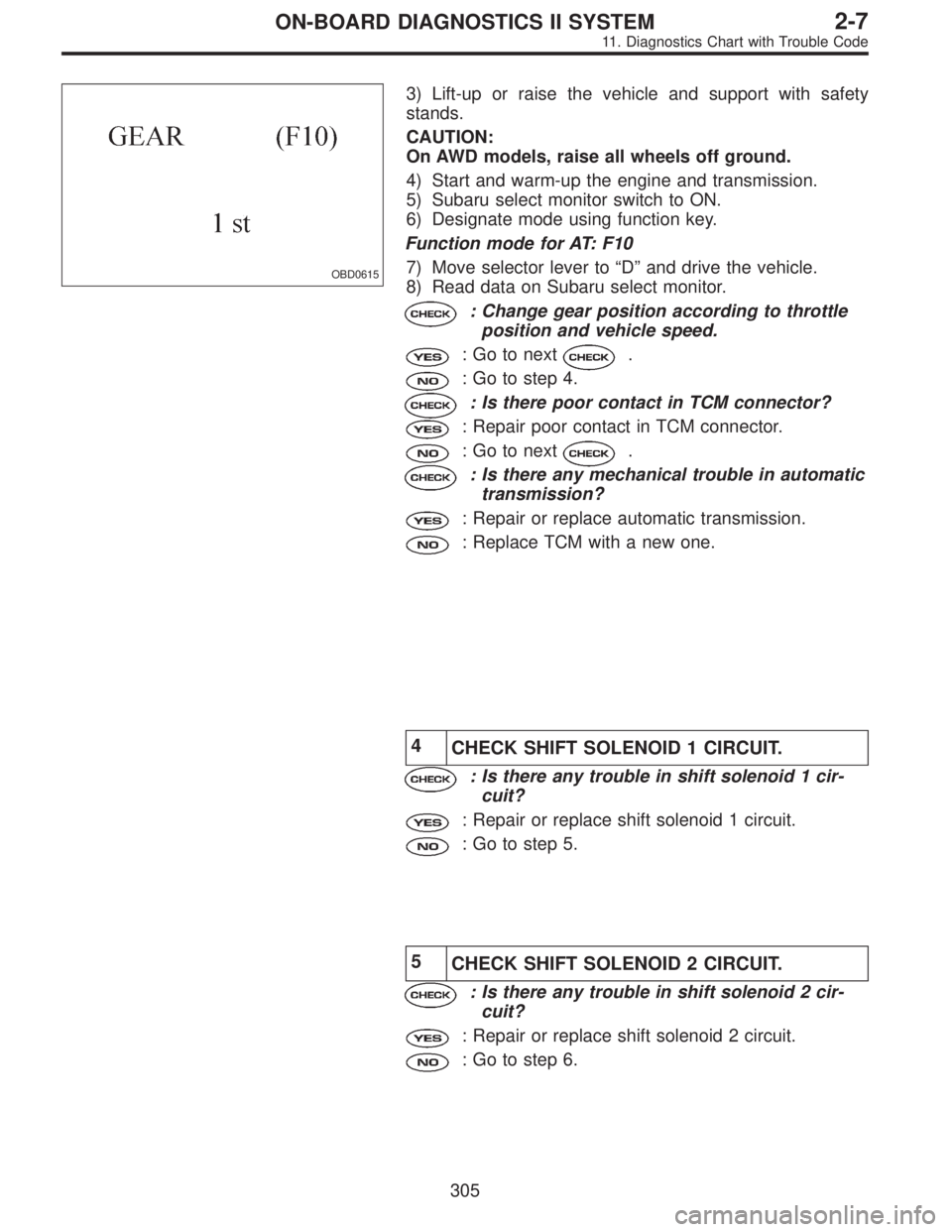
OBD0615
3) Lift-up or raise the vehicle and support with safety
stands.
CAUTION:
On AWD models, raise all wheels off ground.
4) Start and warm-up the engine and transmission.
5) Subaru select monitor switch to ON.
6) Designate mode using function key.
Function mode for AT: F10
7) Move selector lever to“D”and drive the vehicle.
8) Read data on Subaru select monitor.
: Change gear position according to throttle
position and vehicle speed.
: Go to next.
: Go to step 4.
: Is there poor contact in TCM connector?
: Repair poor contact in TCM connector.
: Go to next.
: Is there any mechanical trouble in automatic
transmission?
: Repair or replace automatic transmission.
: Replace TCM with a new one.
4
CHECK SHIFT SOLENOID 1 CIRCUIT.
: Is there any trouble in shift solenoid 1 cir-
cuit?
: Repair or replace shift solenoid 1 circuit.
: Go to step 5.
5
CHECK SHIFT SOLENOID 2 CIRCUIT.
: Is there any trouble in shift solenoid 2 cir-
cuit?
: Repair or replace shift solenoid 2 circuit.
: Go to step 6.
305
2-7ON-BOARD DIAGNOSTICS II SYSTEM
11. Diagnostics Chart with Trouble Code
Page 1512 of 2248
6
CHECK SHIFT SOLENOID 3 CIRCUIT.
: Is there any trouble in shift solenoid 3 cir-
cuit?
: Repair or replace shift solenoid 3 circuit.
: Go to next.
: Is there poor contact in TCM connector?
: Repair poor contact in TCM connector.
: Go to next.
: Is there any mechanical trouble in automatic
transmission?
: Repair or replace automatic transmission.
: Replace TCM with a new one.
306
2-7ON-BOARD DIAGNOSTICS II SYSTEM
11. Diagnostics Chart with Trouble Code
Page 1519 of 2248

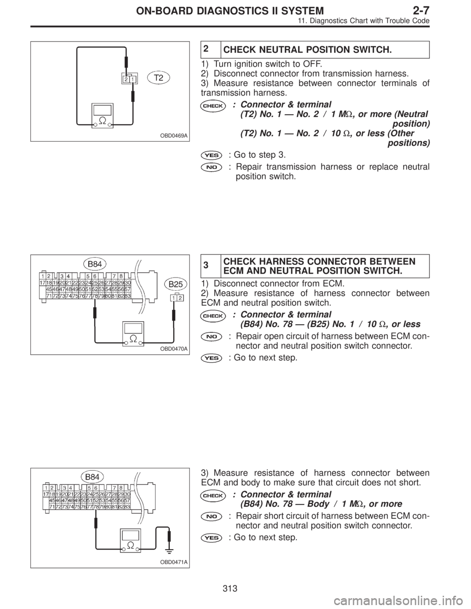
OBD0469A
2
CHECK NEUTRAL POSITION SWITCH.
1) Turn ignition switch to OFF.
2) Disconnect connector from transmission harness.
3) Measure resistance between connector terminals of
transmission harness.
: Connector & terminal
(T2) No. 1—No. 2 / 1 MΩ, or more (Neutral
position)
(T2) No. 1—No. 2 / 10Ω, or less (Other
positions)
: Go to step 3.
: Repair transmission harness or replace neutral
position switch.
OBD0470A
3CHECK HARNESS CONNECTOR BETWEEN
ECM AND NEUTRAL POSITION SWITCH.
1) Disconnect connector from ECM.
2) Measure resistance of harness connector between
ECM and neutral position switch.
: Connector & terminal
(B84) No. 78—(B25) No. 1 / 10Ω, or less
: Repair open circuit of harness between ECM con-
nector and neutral position switch connector.
: Go to next step.
OBD0471A
3) Measure resistance of harness connector between
ECM and body to make sure that circuit does not short.
: Connector & terminal
(B84) No. 78—Body / 1 MΩ, or more
: Repair short circuit of harness between ECM con-
nector and neutral position switch connector.
: Go to next step.
313
2-7ON-BOARD DIAGNOSTICS II SYSTEM
11. Diagnostics Chart with Trouble Code
Page 1521 of 2248
OBD0473
BE: DTC P1101
—NEUTRAL POSITION SWITCH CIRCUIT
MALFUNCTION [AT VEHICLES] (N
—SW)—
DESCRIPTION:
Refer to“AN: DTC P0705—TRANSMISSION RANGE
SENSOR CIRCUIT MALFUNCTION—[T11AN0]”.
DTC DETECTING CONDITION:
�Two consecutive trips with fault
TROUBLE SYMPTOM:
�Erroneous idling
1.Check input signal for ECM.
2.Check harness connector between ECM and
inhibitor switch.
3.Check inhibitor switch.
CAUTION:
After repair or replacement of faulty parts, conduct
CLEAR MEMORY and INSPECTION MODES.
[T3D0] and [T3E0].>
�
�
315
2-7ON-BOARD DIAGNOSTICS II SYSTEM
11. Diagnostics Chart with Trouble Code
Page 1523 of 2248
OBD0477A
2CHECK HARNESS CONNECTOR BETWEEN
ECM AND INHIBITOR SWITCH.
1) Turn ignition switch to OFF.
2) Disconnect connectors from ECM and transmission.
3) Measure resistance of harness connector between
ECM and transmission.
: Connector & terminal
(B84) No. 78—(B12) No. 12 / 10Ω, or less
: Repair open circuit of harness between ECM con-
nector and transmission connector.
: Go to next step.
OBD0471A
4) Measure resistance of harness connector between
ECM and body.
: Connector & terminal
(B84) No. 78—Body / 1 MΩ, or more
: Repair short circuit of harness between ECM con-
nector and transmission connector.
: Go to next step.
OBD0479A
5) Measure resistance of harness connector between
inhibitor switch and body.
: Connector & terminal
(B12) No. 11—Body / 10Ω, or less
: Go to step 3.
: Repair open circuit of inhibitor switch ground line.
317
2-7ON-BOARD DIAGNOSTICS II SYSTEM
11. Diagnostics Chart with Trouble Code