Page 1453 of 2248
1
CHECK TRANSMISSION TYPE.
Refer to flow chart on page 245.
2CHECK ANY OTHER DTC P0105, P0106,
P0443 AND P1102 ON DISPLAY.
: Check that Subaru select monitor or the
OBD-II general scan tool shows P0105,
P0106, P0443 and P1102.
: Inspect the relevant DTC using“11. Diagnostics
chart with Trouble Code”.
: Go to step 3.
3CHECK PURGE CONTROL SOLENOID VALVE
OPERATION.
1) Turn ignition switch to OFF.
2) Connect test mode connector at the lower portion of
instrument panel (on the driver’s side), to the side of the
center console box.
3) Turn ignition switch to ON.
: Make sure that the ON/OFF operating sound
of purge control solenoid valve occurs at
about 0.3 Hz.
: Replace purge control solenoid valve.
: Go to next step.
4) Disconnect canister purge hose from canister.
: Blow through the canister purge hose to
check if pulsations occur.
: Check and repair loose connections, cracks, and
clogging in evaporation line.
: Replace purge control solenoid valve.
247
2-7ON-BOARD DIAGNOSTICS II SYSTEM
11. Diagnostics Chart with Trouble Code
Page 1459 of 2248
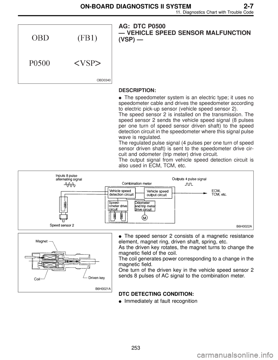
OBD0340
AG: DTC P0500
—VEHICLE SPEED SENSOR MALFUNCTION
(VSP)—
DESCRIPTION:
�The speedometer system is an electric type; it uses no
speedometer cable and drives the speedometer according
to electric pick-up sensor (vehicle speed sensor 2).
The speed sensor 2 is installed on the transmission. The
speed sensor 2 sends the vehicle speed signal (8 pulses
per one turn of speed sensor driven shaft) to the speed
detection circuit in the speedometer where this signal pulse
wave is regulated.
The regulated pulse signal (4 pulses per one turn of speed
sensor driven shaft) is sent to the speedometer drive cir-
cuit and odometer (trip meter) drive circuit.
The output signal from vehicle speed detection circuit is
also used in ECM, TCM, etc.
B6H0022A
B6H0021A
�The speed sensor 2 consists of a magnetic resistance
element, magnet ring, driven shaft, spring, etc.
As the driven key rotates, the magnet turns to change the
magnetic field of the coil.
The coil generates power corresponding to a change in the
magnetic field.
One turn of the driven key in the vehicle speed sensor 2
sends 8 pulses of AC signal to the combination meter.
DTC DETECTING CONDITION:
�Immediately at fault recognition
253
2-7ON-BOARD DIAGNOSTICS II SYSTEM
11. Diagnostics Chart with Trouble Code
Page 1480 of 2248
OBD0591
AN: DTC P0705
—TRANSMISSION RANGE SENSOR CIRCUIT
MALFUNCTION (RNG)—
OBD0592A
DESCRIPTION:
�The inhibitor switch assures safety when starting the
engine. This switch is mounted on the right side of the
transmission case, and is operated by the range selector
lever.
�When the selector lever is set to“P”or“N”, the electri-
cal circuit is connected in the inhibitor switch and the starter
circuit is energized for cracking the engine.
�When the selector lever is set to“R”,“D”,“3”,“2”,or“1”
range, the electrical circuit is disconnected in the inhibitor
switch. Hence engine cranking is disabled. In the“R”
range, the back-up light circuit is completed in the switch,
and the back-up lights come on.
DTC DETECTING CONDITION:
�Two consecutive trips with fault
TROUBLE SYMPTOM:
�Starter does not rotate when selector lever is in“P”or
“N”range.
�Starter rotates when selector lever is in“R”,“D”,“3”,“2”
or“1”range.
�Engine brake is not effected when selector lever is in“3”
range.
�Shift characteristics are erroneous.
274
2-7ON-BOARD DIAGNOSTICS II SYSTEM
11. Diagnostics Chart with Trouble Code
Page 1482 of 2248
OBD0596A
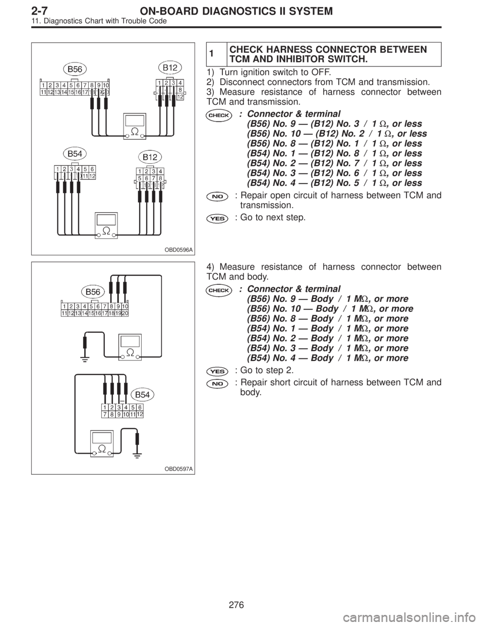
1CHECK HARNESS CONNECTOR BETWEEN
TCM AND INHIBITOR SWITCH.
1) Turn ignition switch to OFF.
2) Disconnect connectors from TCM and transmission.
3) Measure resistance of harness connector between
TCM and transmission.
: Connector & terminal
(B56) No. 9—(B12) No. 3 / 1Ω, or less
(B56) No. 10—(B12) No. 2 / 1Ω, or less
(B56) No. 8—(B12) No. 1 / 1Ω, or less
(B54) No. 1—(B12) No. 8 / 1Ω, or less
(B54) No. 2—(B12) No. 7 / 1Ω, or less
(B54) No. 3—(B12) No. 6 / 1Ω, or less
(B54) No. 4—(B12) No. 5 / 1Ω, or less
: Repair open circuit of harness between TCM and
transmission.
: Go to next step.
OBD0597A
4) Measure resistance of harness connector between
TCM and body.
: Connector & terminal
(B56) No. 9—Body / 1 MΩ, or more
(B56) No. 10—Body / 1 MΩ, or more
(B56) No. 8—Body / 1 MΩ, or more
(B54) No. 1—Body / 1 MΩ, or more
(B54) No. 2—Body / 1 MΩ, or more
(B54) No. 3—Body / 1 MΩ, or more
(B54) No. 4—Body / 1 MΩ, or more
: Go to step 2.
: Repair short circuit of harness between TCM and
body.
276
2-7ON-BOARD DIAGNOSTICS II SYSTEM
11. Diagnostics Chart with Trouble Code
Page 1483 of 2248
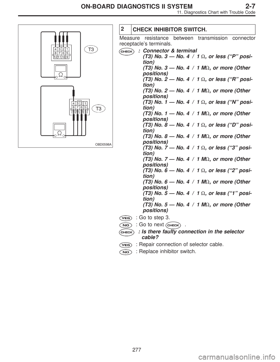
OBD0598A
2
CHECK INHIBITOR SWITCH.
Measure resistance between transmission connector
receptacle’s terminals.
: Connector & terminal
(T3) No. 3—No. 4 / 1Ω, or less (“P”posi-
tion)
(T3) No. 3—No. 4 / 1 MΩ, or more (Other
positions)
(T3) No. 2—No. 4 / 1Ω, or less (“R”posi-
tion)
(T3) No. 2—No. 4 / 1 MΩ, or more (Other
positions)
(T3) No. 1—No. 4 / 1Ω, or less (“N”posi-
tion)
(T3) No. 1—No. 4 / 1 MΩ, or more (Other
positions)
(T3) No. 8—No. 4 / 1Ω, or less (“D”posi-
tion)
(T3) No. 8—No. 4 / 1 MΩ, or more (Other
positions)
(T3) No. 7—No. 4 / 1Ω, or less (“3”posi-
tion)
(T3) No. 7—No. 4 / 1 MΩ, or more (Other
positions)
(T3) No. 6—No. 4 / 1Ω, or less (“2”posi-
tion)
(T3) No. 6—No. 4 / 1 MΩ, or more (Other
positions)
(T3) No. 5—No. 4 / 1Ω, or less (“1”posi-
tion)
(T3) No. 5—No. 4 / 1 MΩ, or more (Other
positions)
: Go to step 3.
: Go to next.
: Is there faulty connection in the selector
cable?
: Repair connection of selector cable.
: Replace inhibitor switch.
277
2-7ON-BOARD DIAGNOSTICS II SYSTEM
11. Diagnostics Chart with Trouble Code
Page 1484 of 2248
OBD0595A
3
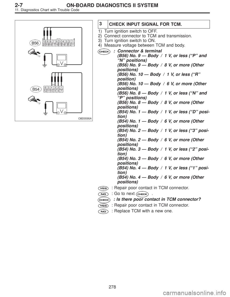
CHECK INPUT SIGNAL FOR TCM.
1) Turn ignition switch to OFF.
2) Connect connector to TCM and transmission.
3) Turn ignition switch to ON.
4) Measure voltage between TCM and body.
: Connector & terminal
(B56) No. 9—Body / 1 V, or less (“P”and
“N”positions)
(B56) No. 9—Body / 8 V, or more (Other
positions)
(B56) No. 10—Body / 1 V, or less (“R”
position)
(B56) No. 10—Body / 6 V, or more (Other
positions)
(B56) No. 8—Body / 1 V, or less (“N”and
“P”positions)
(B56) No. 8—Body / 8 V, or more (Other
positions)
(B54) No. 1—Body / 1 V, or less (“D”posi-
tion)
(B54) No. 1—Body / 6 V, or more (Other
positions)
(B54) No. 2—Body / 1 V, or less (“3”posi-
tion)
(B54) No. 2—Body / 6 V, or more (Other
positions)
(B54) No. 3—Body / 1 V, or less (“2”posi-
tion)
(B54) No. 3—Body / 6 V, or more (Other
positions)
(B54) No. 4—Body / 1 V, or less (“1”posi-
tion)
(B54) No. 4—Body / 6 V, or more (Other
positions)
: Repair poor contact in TCM connector.
: Go to next.
: Is there poor contact in TCM connector?
: Repair poor contact in TCM connector.
: Replace TCM with a new one.
278
2-7ON-BOARD DIAGNOSTICS II SYSTEM
11. Diagnostics Chart with Trouble Code
Page 1485 of 2248
OBD0380
AO: DTC P0710
—TRANSMISSION FLUID TEMPERATURE
SENSOR CIRCUIT MALFUNCTION (ATF)—
H2M1145
DESCRIPTION:
This sensor is mounted to the control valve in the transmis-
sion. It detects temperature change as an analog electrical
signal. The output characteristics of the sensor are shown
in the illustration.
DTC DETECTING CONDITION:
�Two consecutive trips with fault
TROUBLE SYMPTOM:
�No shift up to 4th speed (after engine warm-up)
�No lock-up occurs. (after engine warm-up)
�Excessive shift shock
279
2-7ON-BOARD DIAGNOSTICS II SYSTEM
11. Diagnostics Chart with Trouble Code
Page 1486 of 2248
1.Check harness connector between TCM and
ATF temperature sensor.
2.Check ATF temperature sensor.
3.Check input signal for TCM.
CAUTION:
After repair or replacement of faulty parts, conduct
CLEAR MEMORY and INSPECTION MODES.
[T3D0] and [T3E0].>
WIRING DIAGRAM:
OBD0383
NOTE:
For the diagnostic procedure on transmission fluid tem-
perature sensor circuit, refer to“3-2 [T7G0]”.
�
�
280
2-7ON-BOARD DIAGNOSTICS II SYSTEM
11. Diagnostics Chart with Trouble Code