Page 1524 of 2248
OBD0480A
3
CHECK INHIBITOR SWITCH.
Measure resistance between transmission connector
receptacle’s terminals.
: Connector & terminal
(T3) No. 12—No. 11 / 10Ω, or less
(“N”and“P”positions)
(T3) No. 12—No. 11 / 1 MΩ, or more
(Other positions)
: Go to next.
: Replace inhibitor switch.
: Is there any fault in selector cable connec-
tion to inhibitor switch?
: Repair selector cable connection.
[W2B2].>
: Replace ECM with a new one.
318
2-7ON-BOARD DIAGNOSTICS II SYSTEM
11. Diagnostics Chart with Trouble Code
Page 1526 of 2248
1.Check transmission type.
AT
�MT
Check AT/MT identification circuit.
2.Check output signal from ECM.
�
3.Check harness connector.
4.Check harness connector.
5.Check pressure sources switching solenoid
valve.
6.Check power supply to pressure sources
switching solenoid valve.
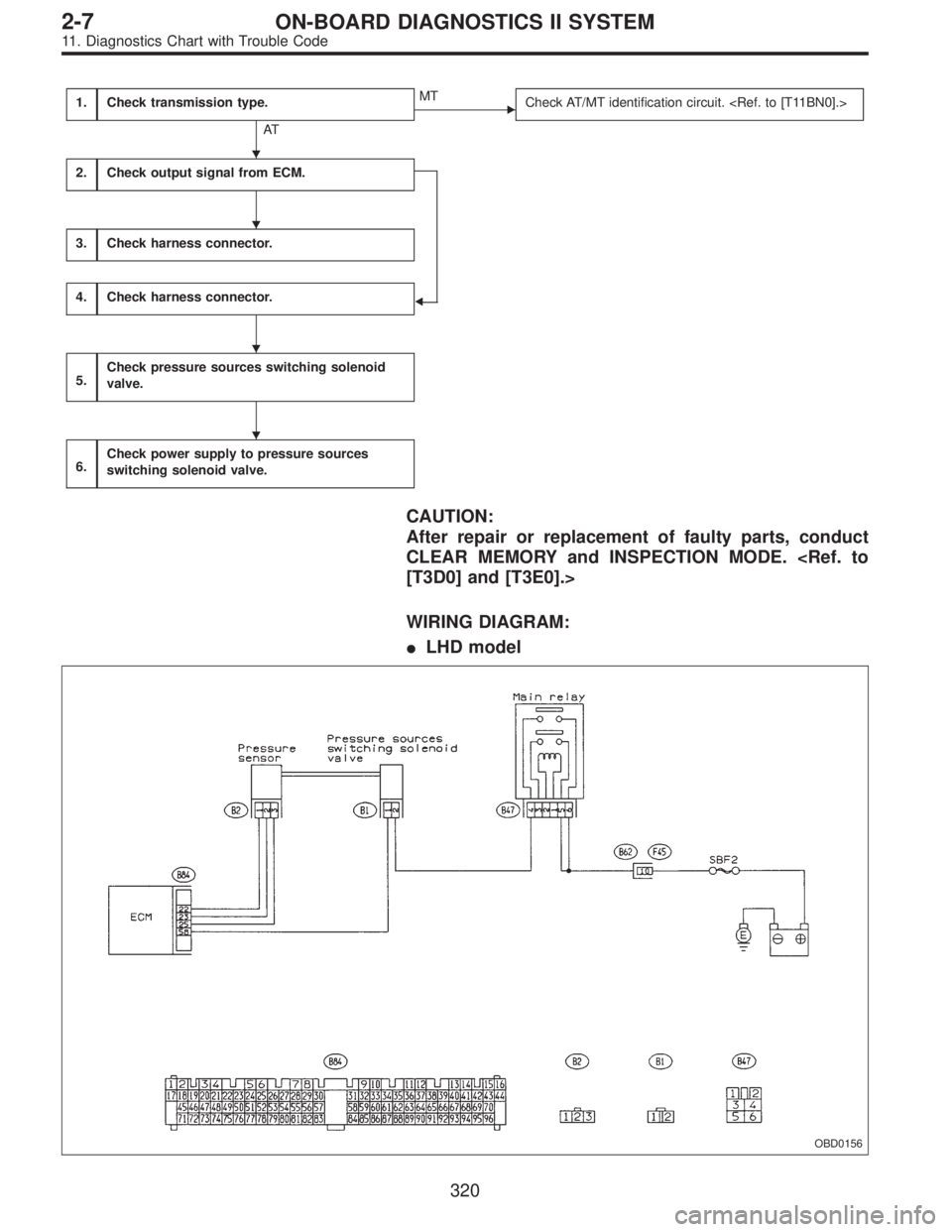
CAUTION:
After repair or replacement of faulty parts, conduct
CLEAR MEMORY and INSPECTION MODE.
[T3D0] and [T3E0].>
WIRING DIAGRAM:
�LHD model
OBD0156
�
�
�
�
320
2-7ON-BOARD DIAGNOSTICS II SYSTEM
11. Diagnostics Chart with Trouble Code
Page 1527 of 2248
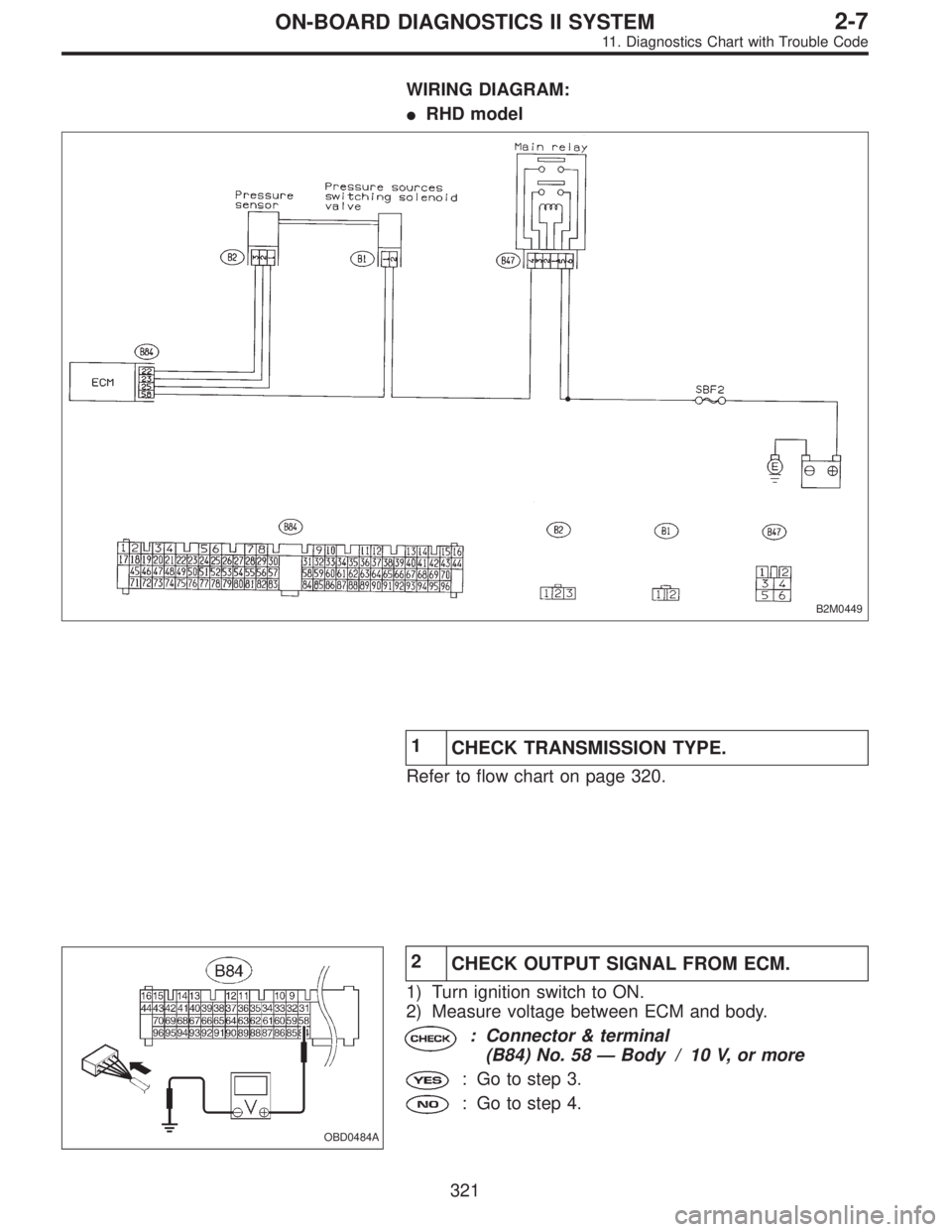
WIRING DIAGRAM:
�RHD model
B2M0449
1
CHECK TRANSMISSION TYPE.
Refer to flow chart on page 320.
OBD0484A
2
CHECK OUTPUT SIGNAL FROM ECM.
1) Turn ignition switch to ON.
2) Measure voltage between ECM and body.
: Connector & terminal
(B84) No. 58—Body / 10 V, or more
: Go to step 3.
: Go to step 4.
321
2-7ON-BOARD DIAGNOSTICS II SYSTEM
11. Diagnostics Chart with Trouble Code
Page 1547 of 2248
OBD0501
BK: DTC P1700
—THROTTLE POSITION SENSOR CIRCUIT
MALFUNCTION FOR AUTOMATIC
TRANSMISSION (ATTH)—
DESCRIPTION:
�The throttle position sensor provides electrical signals
corresponding to the throttle opening. The throttle opening
and accelerator depression speed are detected by this
throttle position sensor output.
�Detects throttle opening and determines shift point, line
pressure and lockup vehicle speed according to engine
load.
SOR CIRCUIT MALFUNCTION—[T11G0]”.>
DTC DETECTING CONDITION:
�Two consecutive trips with fault
TROUBLE SYMPTOM:
�Shift point too high or too low; engine brake not effected
in“3”range; excessive shift shock; excessive tight corner
“braking”
341
2-7ON-BOARD DIAGNOSTICS II SYSTEM
11. Diagnostics Chart with Trouble Code
Page 1549 of 2248
OBD0511
BL: DTC P1701
—CRUISE CONTROL SET SIGNAL CIRCUIT
MALFUNCTION FOR AUTOMATIC
TRANSMISSION (CRS)—
DESCRIPTION:
Detects operation of cruise control, and expands“4th”
operating range.
DTC DETECTING CONDITION:
�Two consecutive trips with fault
1.Check harness connector between TCM and
CCM.
2.Check input signal for TCM.
CAUTION:
After repair or replacement of faulty parts, conduct
CLEAR MEMORY and INSPECTION MODES.
[T3D0] and [T3E0].>
�
343
2-7ON-BOARD DIAGNOSTICS II SYSTEM
11. Diagnostics Chart with Trouble Code
Page 1552 of 2248
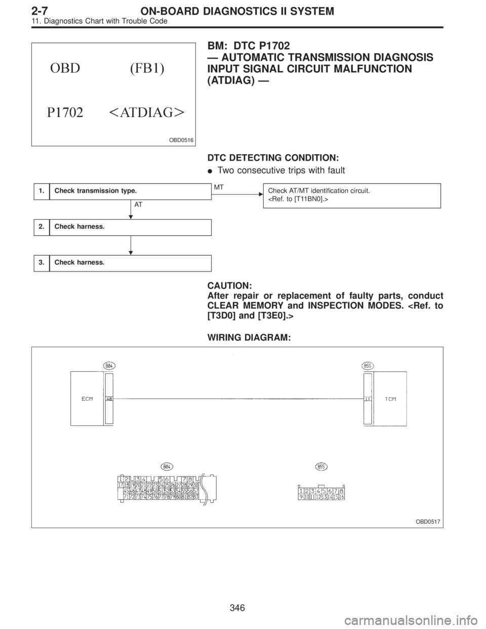
OBD0516
BM: DTC P1702
—AUTOMATIC TRANSMISSION DIAGNOSIS
INPUT SIGNAL CIRCUIT MALFUNCTION
(ATDIAG)—
DTC DETECTING CONDITION:
�Two consecutive trips with fault
1.Check transmission type.
AT
�MT
Check AT/MT identification circuit.
2.Check harness.
3.Check harness.
CAUTION:
After repair or replacement of faulty parts, conduct
CLEAR MEMORY and INSPECTION MODES.
[T3D0] and [T3E0].>
WIRING DIAGRAM:
OBD0517
�
�
346
2-7ON-BOARD DIAGNOSTICS II SYSTEM
11. Diagnostics Chart with Trouble Code
Page 1553 of 2248
 Turn ignition switch to ON.
2) Measure voltage between ECM connector and body.
: Connector & terminal
(B84) No.")
1
CHECK TRANSMISSION TYPE.
Refer to flow chart on page 346.
OBD0737A
2
CHECK HARNESS.
1) Turn ignition switch to ON.
2) Measure voltage between ECM connector and body.
: Connector & terminal
(B84) No. 48—Body / 4 V, or more
:�Open circuit of harness between ECM connec-
tor and TCM connector
�Poor contact in ECM connector
�Poor contact in TCM connector
Check the above and repair if necessary.
: Go to next.
: Connector & terminal
(B84) No. 48—Body / 1 V, or less
: Go to step 3.
: Although MIL illuminates, circuit is now normal.
Check all connectors for possible poor contact
between ECM connector and TCM connector.
OBD0519A
3
CHECK HARNESS.
1) Turn ignition switch to OFF.
2) Disconnect connector from ECM.
3) Measure resistance between ECM harness connector
and body.
: Connector & terminal
(B84) No. 48—Body / 10Ω, or less
: Repair short circuit of harness between ECM con-
nector and TCM connector.
: Repair poor contact in ECM connector.
347
2-7ON-BOARD DIAGNOSTICS II SYSTEM
11. Diagnostics Chart with Trouble Code
Page 1555 of 2248
1. Supplemental Restraint System
“Airbag”
Airbag system wiring harness is routed near the transmis-
sion control module (TCM).
�All Airbag system wiring harness and connectors
are colored yellow. Do not use electrical test equip-
ment on these circuit.
�Be careful not to damage Airbag system wiring har-
ness when performing diagnostics and servicing the
TCM.
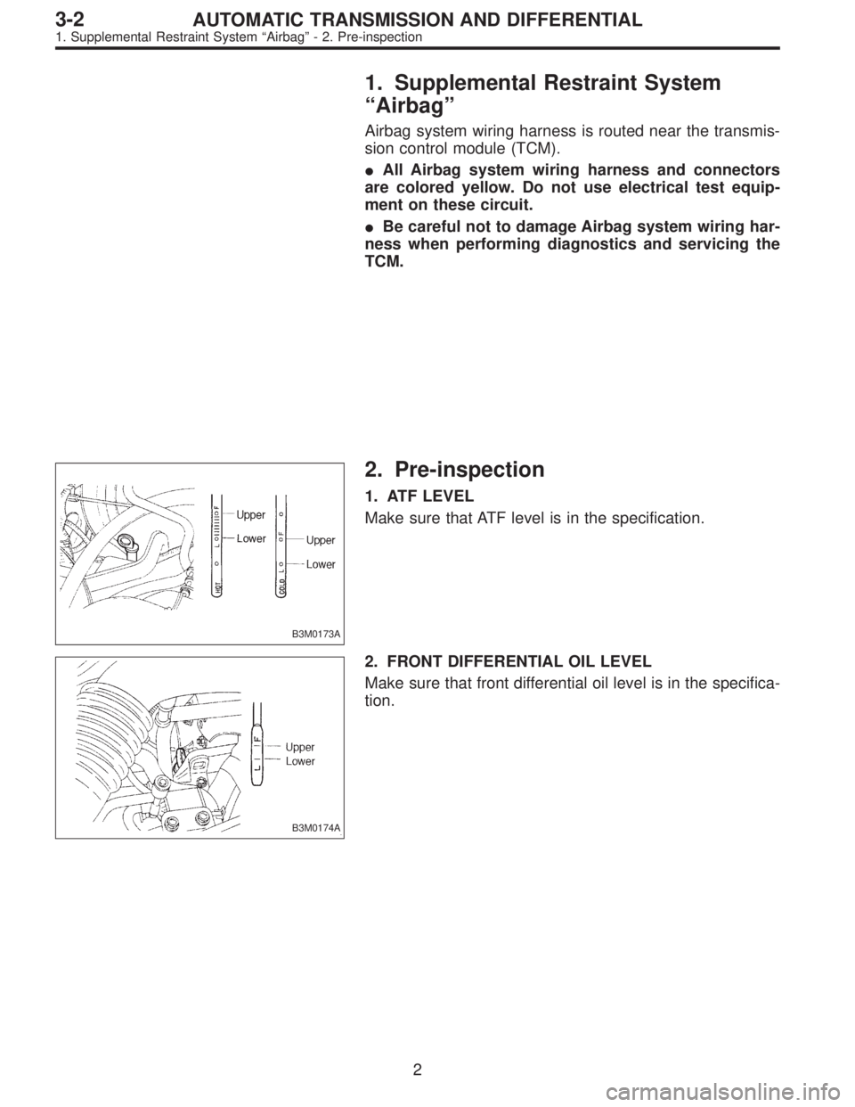
B3M0173A
2. Pre-inspection
1. ATF LEVEL
Make sure that ATF level is in the specification.
B3M0174A
2. FRONT DIFFERENTIAL OIL LEVEL
Make sure that front differential oil level is in the specifica-
tion.
2
3-2AUTOMATIC TRANSMISSION AND DIFFERENTIAL
1. Supplemental Restraint System“Airbag”- 2. Pre-inspection
 No. 12—No. 11 / 10Ω, or less
(“N”and“P”positions)")
—
DESCRIPTION:
Detects operation of cruise control, and expands“4th”
operating range.
DTC D")