Page 1580 of 2248

D: TROUBLE CODE 14
—SHIFT SOLENOID 2—
DIAGNOSIS:
Output signal circuit of shift solenoid 2 is open or shorted.
TROUBLE SYMPTOM:
No shift
1. Check harness and connectors between TCM
and shift solenoid 2.
OK
�Not OK
Repair or replace harness connectors.
2. Check shift solenoid 2’s ground line.
OK
�Not OK
Repair ground line.
3. Check shift solenoid 2.
OK
�Not OK
Replace shift solenoid 2.
4. Check output signal emitted from TCM.
OK
�Not OK
�Repair TCM connector terminal poor contact.
�Replace TCM.
�Repair TCM connector terminal poor contact.
OBD0444
OBD0446A
1. CHECK HARNESS AND CONNECTORS BETWEEN
TCM AND SHIFT SOLENOID 2.
1) Turn ignition switch to OFF.
2) Disconnect connectors from TCM and transmission.
3) Measure resistance of harness connector between
TCM and transmission connector.
Connector & terminal / Specified resistance:
(B55) No. 13—(B11)No.2/1Ω, or less
(B55) No. 10—(B11)No.4/1Ω, or less
�
�
�
�
25
3-2AUTOMATIC TRANSMISSION AND DIFFERENTIAL
7. Diagnostic Chart with Trouble Code
Page 1581 of 2248
 Measure resistance of harness connector between
TCM and body to make sure that circuit does not short.
Connector & terminal / Specified resistance:
(B55) No. 13—Body/1MΩ, or more
(B55)")
OBD0447A
4) Measure resistance of harness connector between
TCM and body to make sure that circuit does not short.
Connector & terminal / Specified resistance:
(B55) No. 13—Body/1MΩ, or more
(B55) No. 10—Body/1MΩ, or more
G3M0109
2. CHECK SHIFT SOLENOID 2’s GROUND LINE.
Measure resistance between transmission connector
receptacle and transmission case.
Connector & terminal / Specified resistance:
(T4) No. 4—Transmission / 1Ω, or less
G3M0120
3. CHECK SHIFT SOLENOID 2.
Measure resistance between transmission connector
receptacle’s terminals.
Connector & terminal / Specified resistance:
(T4) No. 2—No.4/20—32Ω
OBD0445A
4. CHECK OUTPUT SIGNAL EMITTED FROM TCM.
1) Connect connectors to TCM and transmission.
2) Lift-up or raise the vehicle and support with safety
stands.
CAUTION:
On AWD models, raise all wheels off ground.
3) Start and warm-up the engine and transmission.
4) Idle the engine.
5) Move selector lever to“D”.
6) Measure voltage between TCM connector terminals.
Connector & terminal / Specified voltage:
(B55) No. 13—No. 10 / 9 V, or more
NOTE:
The speed difference between front and rear wheels may
light either the ABS or the ABS/TCS warning light, but this
indicates no malfunctions. When AT control diagnosis is
finished, perform the ABS or the ABS/TCS memory clear-
ance procedure of self-diagnosis system.
26
3-2AUTOMATIC TRANSMISSION AND DIFFERENTIAL
7. Diagnostic Chart with Trouble Code
Page 1582 of 2248

E: TROUBLE CODE 15
—SHIFT SOLENOID 1—
DIAGNOSIS:
Output signal circuit of shift solenoid 1 is open or shorted.
TROUBLE SYMPTOM:
No shift
1. Check harness and connectors between TCM
and shift solenoid 1.
OK
�Not OK
Repair or replace harness connectors.
2. Check shift solenoid 1’s ground line.
OK
�Not OK
Repair ground line.
3. Check shift solenoid 1.
OK
�Not OK
Replace shift solenoid 1.
4. Check output signal emitted from TCM.
OK
�Not OK
�Repair TCM connector terminal poor contact.
�Replace TCM.
�Repair TCM connector terminal poor contact.
OBD0436
OBD0438A
1. CHECK HARNESS AND CONNECTORS BETWEEN
TCM AND SHIFT SOLENOID 1.
1) Turn ignition switch to OFF.
2) Disconnect connectors from TCM and transmission.
3) Measure resistance of harness connector between
TCM and transmission connector.
Connector & terminal / Specified resistance:
(B55) No. 14—(B11)No.3/1Ω, or less
(B55) No. 10—(B11)No.4/1Ω, or less
�
�
�
�
27
3-2AUTOMATIC TRANSMISSION AND DIFFERENTIAL
7. Diagnostic Chart with Trouble Code
Page 1583 of 2248
 Measure resistance of harness connector between
TCM and body to make sure that circuit does not short.
Connector & terminal / Specified resistance:
(B55) No. 14—Body/1MΩ, or more
(B55)")
OBD0439A
4) Measure resistance of harness connector between
TCM and body to make sure that circuit does not short.
Connector & terminal / Specified resistance:
(B55) No. 14—Body/1MΩ, or more
(B55) No. 10—Body/1MΩ, or more
G3M0109
2. CHECK SHIFT SOLENOID 1’s GROUND LINE.
Measure resistance between transmission connector
receptacle and transmission case.
Connector & terminal / Specified resistance:
(T4) No. 4—Transmission / 1Ω, or less
G3M0123
3. CHECK SHIFT SOLENOID 1.
Measure resistance between transmission connector
receptacle’s terminals.
Connector & terminal / Specified resistance:
(T4) No. 3—No.4/20—32Ω
OBD0437A
4. CHECK OUTPUT SIGNAL EMITTED FROM TCM.
1) Connect connectors to TCM and transmission.
2) Lift-up or raise the vehicle and support with safety
stands.
CAUTION:
On AWD models, raise all wheels off ground.
3) Start and warm-up the engine and transmission.
4) Idle the engine.
5) Move selector lever to“D”.
6) Measure voltage between TCM connector terminals.
Connector & terminal / Specified voltage:
(B55) No. 14—No. 10 / 9 V, or more
NOTE:
The speed difference between front and rear wheels may
light either the ABS or the ABS/TCS warning light, but this
indicates no malfunctions. When AT control diagnosis is
finished, perform the ABS or the ABS/TCS memory clear-
ance procedure of self-diagnosis system.
28
3-2AUTOMATIC TRANSMISSION AND DIFFERENTIAL
7. Diagnostic Chart with Trouble Code
Page 1584 of 2248
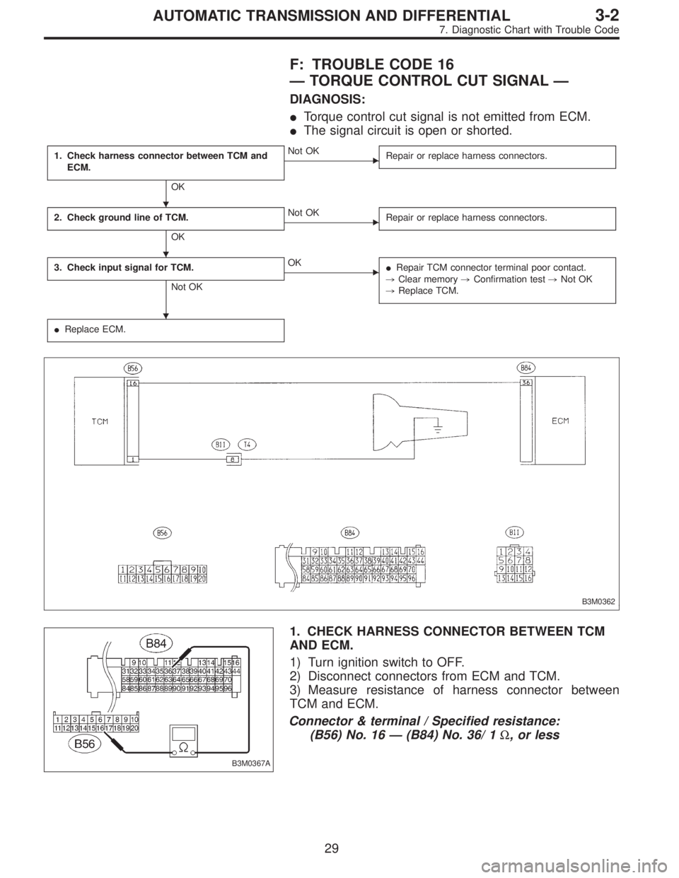
F: TROUBLE CODE 16
—TORQUE CONTROL CUT SIGNAL—
DIAGNOSIS:
�Torque control cut signal is not emitted from ECM.
�The signal circuit is open or shorted.
1. Check harness connector between TCM and
ECM.
OK
�Not OK
Repair or replace harness connectors.
2. Check ground line of TCM.
OK
�Not OK
Repair or replace harness connectors.
3. Check input signal for TCM.
Not OK
�OK
�Repair TCM connector terminal poor contact.
,Clear memory,Confirmation test,Not OK
,Replace TCM.
�Replace ECM.
B3M0362
B3M0367A
1. CHECK HARNESS CONNECTOR BETWEEN TCM
AND ECM.
1) Turn ignition switch to OFF.
2) Disconnect connectors from ECM and TCM.
3) Measure resistance of harness connector between
TCM and ECM.
Connector & terminal / Specified resistance:
(B56) No. 16—(B84) No. 36/ 1Ω, or less
�
�
�
29
3-2AUTOMATIC TRANSMISSION AND DIFFERENTIAL
7. Diagnostic Chart with Trouble Code
Page 1585 of 2248
 Measure resistance of harness connector between
TCM and body to make sure that circuit does not short.
Connector & terminal / Specified resistance:
(B56) No. 16—Body/1MΩ, or more
B3M02")
B3M0216B
4) Measure resistance of harness connector between
TCM and body to make sure that circuit does not short.
Connector & terminal / Specified resistance:
(B56) No. 16—Body/1MΩ, or more
B3M0214B
2. CHECK GROUND LINE OF TCM.
Measure resistance of harness connector between TCM
and body.
Connector & terminal / Specified resistance:
(B56) No. 1—Body / 1Ω, or less
B3M0363A
3. CHECK INPUT SIGNAL FOR TCM.
1) Connect connectors to ECM and TCM.
2) Turn ignition switch to ON.
3) Measure voltage between TCM and body.
Connector & terminal / Specified voltage:
(B56) No. 16—Body / 6—9V
B3M0212B
�Using oscilloscope:
(1) Connect connectors to ECM and TCM.
(2) Set oscilloscope to TCM connector terminals.
Connector & terminals:
Positive probe; (B56) No. 16
Earth lead; Body
B3M0213A
(3) Measure voltage while starting the engine.
CAUTION:
Make sure that signal voltage is below 1 V for one
second after starting the engine (point�
A).
Vm: 6—9V
S: 1 second
30
3-2AUTOMATIC TRANSMISSION AND DIFFERENTIAL
7. Diagnostic Chart with Trouble Code
Page 1586 of 2248
G: TROUBLE CODE 21
—ATF TEMPERATURE SENSOR—
DIAGNOSIS:
Input signal circuit of TCM to ATF temperature sensor is
open or shorted.
TROUBLE SYMPTOM:
Excessive shift shock
1. Check harness and connectors between TCM
and ATF temperature sensor.
OK
�Not OK
Repair or replace harness connectors.
2. Check ATF temperature sensor.
OK
�Not OK
Replace ATF temperature sensor.
3. Check input signal for TCM.
Not OK
�OK
�Repair TCM connector terminal poor contact.
�Repair TCM connector terminal poor contact.
�Replace TCM.
B3M0411
�
�
�
31
3-2AUTOMATIC TRANSMISSION AND DIFFERENTIAL
7. Diagnostic Chart with Trouble Code
Page 1587 of 2248
 Turn ignition switch to OFF.
2) Disconnect connectors from TCM and transmission.
3) Measure resistance of harness co")
OBD0388A
1. CHECK HARNESS AND CONNECTORS BETWEEN
TCM AND ATF TEMPERATURE SENSOR.
1) Turn ignition switch to OFF.
2) Disconnect connectors from TCM and transmission.
3) Measure resistance of harness connector between
TCM and transmission connector.
Connector & terminal / Specified voltage:
(B54) No. 10—(B11)No.5/1Ω, or less
(B56) No. 20—(B11) No. 12 / 1Ω, or less
B3M0220B
4) Measure resistance of harness connector between
TCM and body to make sure that circuit does not short.
Connector & terminal / Specified resistance:
(B54) No. 10—Body/1MΩ, or more
(B56) No. 20—Body/1MΩ, or more
G3M0126
2. CHECK ATF TEMPERATURE SENSOR.
1) Measure resistance between transmission connector
receptacle’s terminals.
Connector & terminal / Specified resistance:
(T4) No. 5—No. 12 /
2.1—2.9 kΩ[ATF temperature: 20°C (68°F)]
2) Connect connectors to transmission and TCM.
3) Start and warm-up the engine until ATF temperature
has increased.
4) Stop the engine and disconnect connector from trans-
mission.
5) Measure resistance between transmission connector
receptacle’s terminals.
Connector & terminal / Specified resistance:
(T4) No. 5—No. 12 /
275—375Ω[ATF temperature: 80°C (176°F)]
32
3-2AUTOMATIC TRANSMISSION AND DIFFERENTIAL
7. Diagnostic Chart with Trouble Code