Page 1427 of 2248
—
OBD0293A
DESCRIPTION:
�The crankshaft position sensor is installed on the oil
pump, located in the front center portio")
OBD0292
Z: DTC P0335
—CRANKSHAFT POSITION SENSOR
CIRCUIT MALFUNCTION (CRANK)—
OBD0293A
DESCRIPTION:
�The crankshaft position sensor is installed on the oil
pump, located in the front center portion of the cylinder
block, to detect the crankshaft position. It is designed so
that the ECM accurately reads the number of pulses which
occur when protrusions provided at the perimeter of the
crankshaft sprocket (rotating together with the crankshaft)
cross the crankshaft position sensor.
�The crankshaft position sensor is a molded type which
consists of a magnet, core, coil, terminals, etc.
�
1Terminal
�
2Yoke core
�
3Magnet
�
4Coil
�
5Core
�
6Cover
OBD0294A
�The crankshaft sprocket is provided with six protrusions.
Crankshaft rotation causes these protrusions to cross the
crankshaft position sensor so that magnetic fluxes in the
coil change with the change in air gap between the sensor
pick-up and the sprocket. The change in air gap induces an
electromotive force which is transmitted to the ECM.
221
2-7ON-BOARD DIAGNOSTICS II SYSTEM
11. Diagnostics Chart with Trouble Code
Page 1435 of 2248
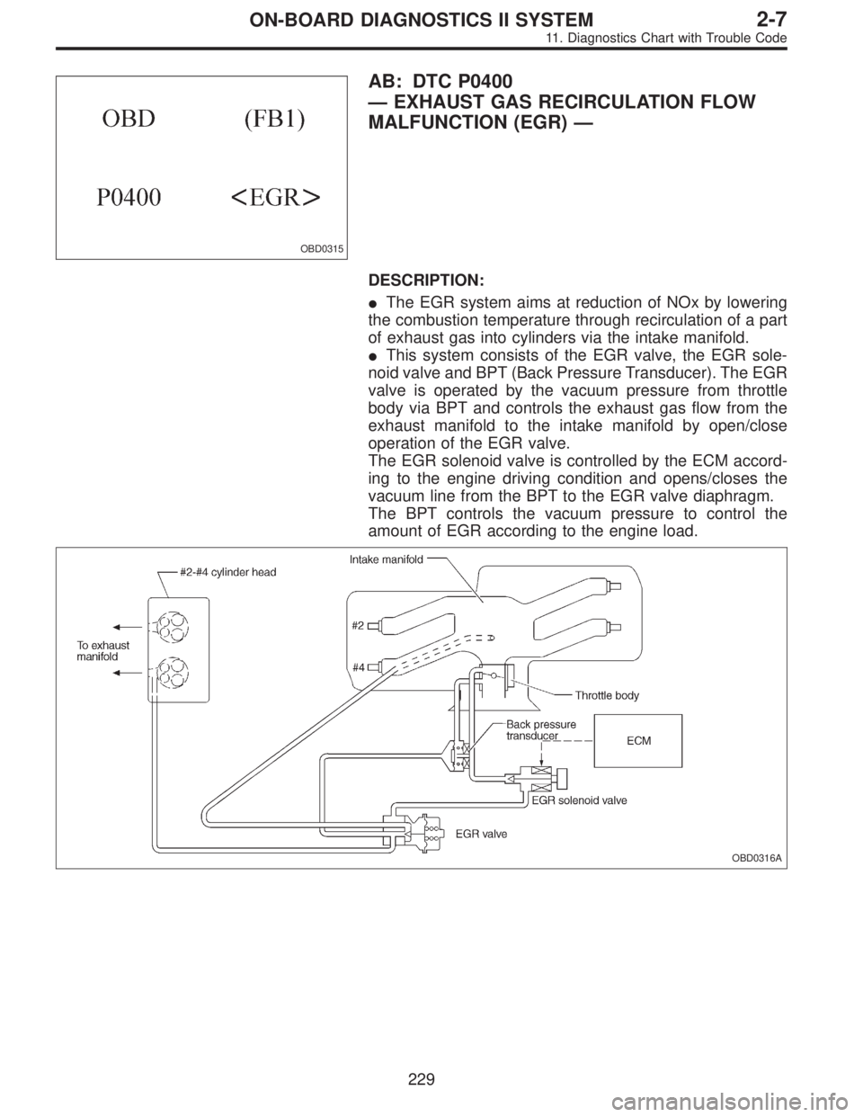
OBD0315
AB: DTC P0400
—EXHAUST GAS RECIRCULATION FLOW
MALFUNCTION (EGR)—
DESCRIPTION:
�The EGR system aims at reduction of NOx by lowering
the combustion temperature through recirculation of a part
of exhaust gas into cylinders via the intake manifold.
�This system consists of the EGR valve, the EGR sole-
noid valve and BPT (Back Pressure Transducer). The EGR
valve is operated by the vacuum pressure from throttle
body via BPT and controls the exhaust gas flow from the
exhaust manifold to the intake manifold by open/close
operation of the EGR valve.
The EGR solenoid valve is controlled by the ECM accord-
ing to the engine driving condition and opens/closes the
vacuum line from the BPT to the EGR valve diaphragm.
The BPT controls the vacuum pressure to control the
amount of EGR according to the engine load.
OBD0316A
229
2-7ON-BOARD DIAGNOSTICS II SYSTEM
11. Diagnostics Chart with Trouble Code
Page 1436 of 2248
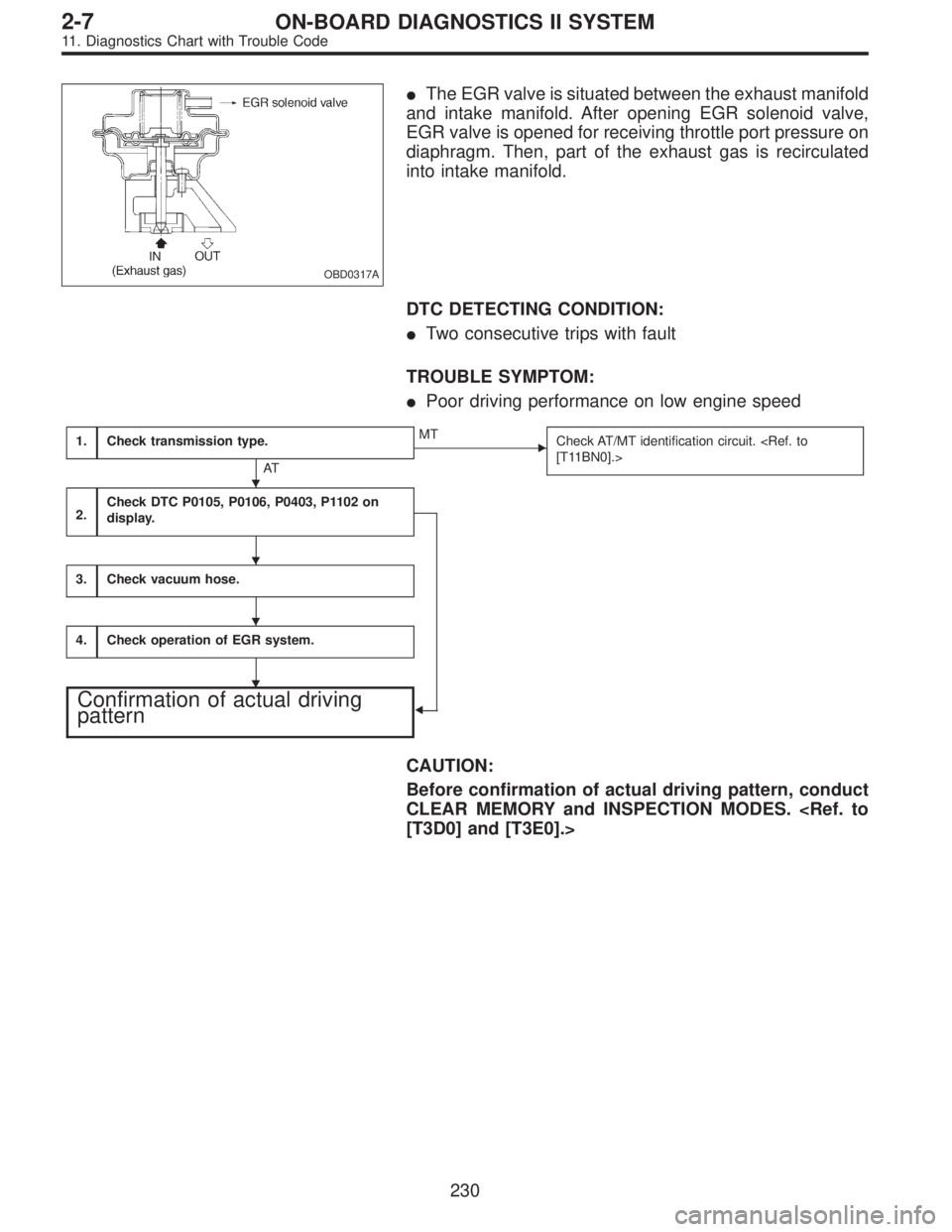
OBD0317A
�The EGR valve is situated between the exhaust manifold
and intake manifold. After opening EGR solenoid valve,
EGR valve is opened for receiving throttle port pressure on
diaphragm. Then, part of the exhaust gas is recirculated
into intake manifold.
DTC DETECTING CONDITION:
�Two consecutive trips with fault
TROUBLE SYMPTOM:
�Poor driving performance on low engine speed
1.Check transmission type.
AT
�MT
Check AT/MT identification circuit.
[T11BN0].>
2.Check DTC P0105, P0106, P0403, P1102 on
display.
�
3.Check vacuum hose.
4.Check operation of EGR system.
Confirmation of actual driving
pattern
CAUTION:
Before confirmation of actual driving pattern, conduct
CLEAR MEMORY and INSPECTION MODES.
[T3D0] and [T3E0].>
�
�
�
�
230
2-7ON-BOARD DIAGNOSTICS II SYSTEM
11. Diagnostics Chart with Trouble Code
Page 1438 of 2248
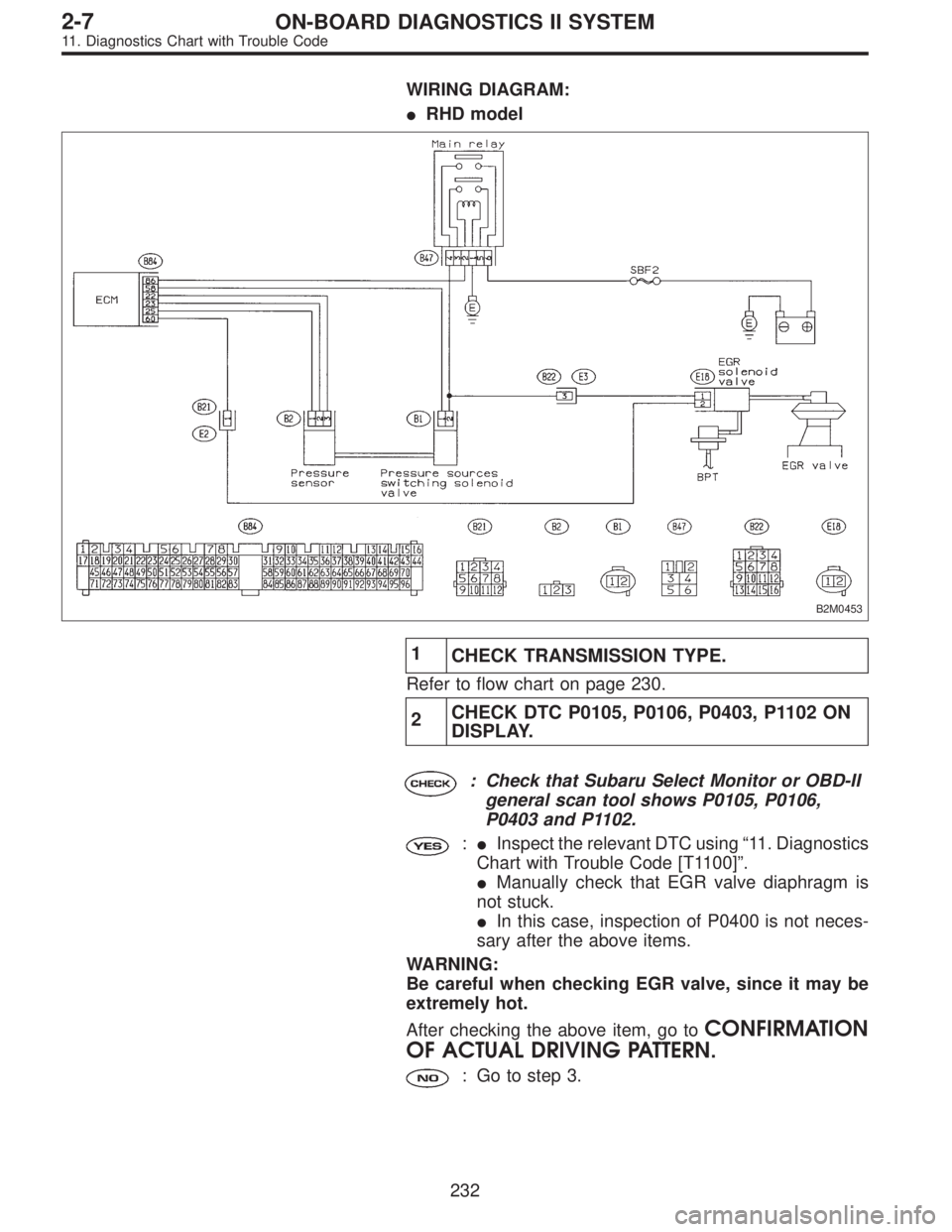
WIRING DIAGRAM:
�RHD model
B2M0453
1
CHECK TRANSMISSION TYPE.
Refer to flow chart on page 230.
2CHECK DTC P0105, P0106, P0403, P1102 ON
DISPLAY.
: Check that Subaru Select Monitor or OBD-II
general scan tool shows P0105, P0106,
P0403 and P1102.
:�Inspect the relevant DTC using“11. Diagnostics
Chart with Trouble Code [T1100]”.
�Manually check that EGR valve diaphragm is
not stuck.
�In this case, inspection of P0400 is not neces-
sary after the above items.
WARNING:
Be careful when checking EGR valve, since it may be
extremely hot.
After checking the above item, go to
CONFIRMATION
OF ACTUAL DRIVING PATTERN.
: Go to step 3.
232
2-7ON-BOARD DIAGNOSTICS II SYSTEM
11. Diagnostics Chart with Trouble Code
Page 1439 of 2248

3
CHECK VACUUM HOSE.
: Check vacuum hoses for disconnection,
leakage and clogging.
: Check and repair the following items.
�Two lines of pipes and hoses running between
throttle body and BPT
�Pipe and hose line connecting BPT and EGR
solenoid valve
�Hose between EGR solenoid valve and EGR
valve
�BPT pressure transmitting hose
: Go to step 4.
4
CHECK OPERATION OF EGR SYSTEM.
1) Turn ignition switch to OFF.
2) Connect the test mode connector.
3) Turn ignition switch to ON.
: Does EGR solenoid valve produce operating
sound?
: Replace EGR solenoid valve.
: Go to next step.
4) Turn ignition switch to OFF.
5) Disconnect connector from EGR solenoid valve.
6) Connect 12 V battery’s ground�terminal to one ter-
minal of the EGR solenoid valve. Then connect 12 V bat-
tery’s�terminal to the other terminal of it.
CAUTION:
Do not use the 12 V battery installed in the vehicle,
because the electrical system may be damaged.
7) Start the engine.
: Open throttle valve by 5 to 10 degrees and
visually check EGR valve operation.
: Possibly EGR valve malfunction may be due to
freezing or clogging by foreign matter. At this point
in time do not replace EGR valve, since it is not
faulty. And after the checking, go to
CONFIR-
MATION OF ACTUAL DRIVING PATTERN.
NOTE:
If malfunction is detected again in the confirmation of actual
driving pattern, EGR valve is faulty. Go to next
.
: Go to next.
233
2-7ON-BOARD DIAGNOSTICS II SYSTEM
11. Diagnostics Chart with Trouble Code
Page 1441 of 2248
OBD0323
AC: DTC P0403
—EXHAUST GAS RECIRCULATION CIRCUIT
MALFUNCTION (EGRSOL)—
OBD0324A
DESCRIPTION:
The EGR solenoid valve is situated between the BPT and
EGR valve. EGR solenoid valve is opened by a signal
emitted from the ECM. Therefore, throttle port pressure is
transmitted to diaphragm of EGR valve.
DTC DETECTING CONDITION:
�Two consecutive trips with fault
TROUBLE SYMPTOM:
�Poor driving performance on low engine speed
1.Check transmission type.
AT
�MT
Check AT/MT identification circuit.
2.Check output signal from ECM.
�
3.Check harness.
4.Check harness.
5.Check EGR solenoid valve.
6.Check power supply to EGR solenoid valve.
CAUTION:
After repair or replacement of faulty parts, conduct
CLEAR MEMORY and INSPECTION MODES.
[T3D0] and [T3E0].>
�
�
�
�
235
2-7ON-BOARD DIAGNOSTICS II SYSTEM
11. Diagnostics Chart with Trouble Code
Page 1443 of 2248
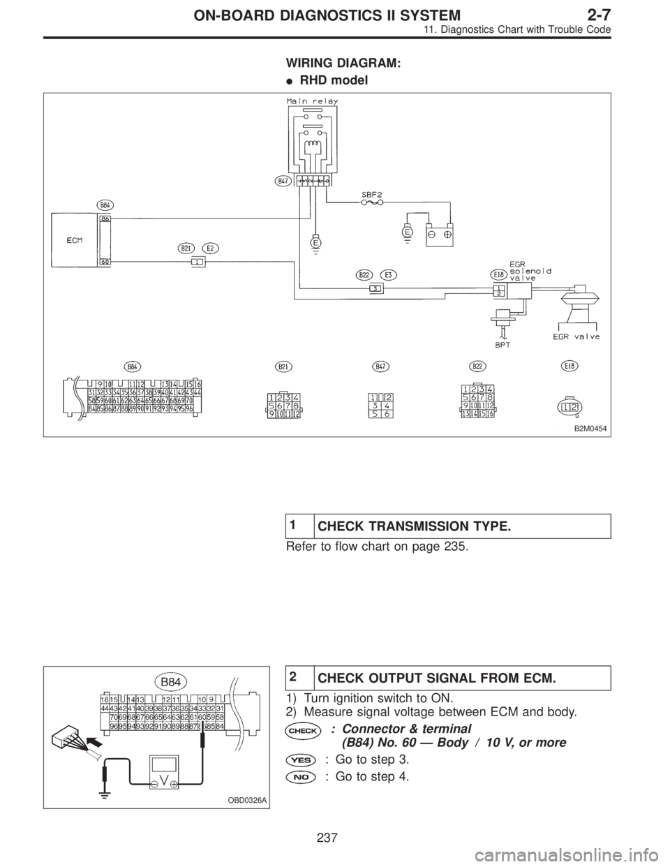
WIRING DIAGRAM:
�RHD model
B2M0454
1
CHECK TRANSMISSION TYPE.
Refer to flow chart on page 235.
OBD0326A
2
CHECK OUTPUT SIGNAL FROM ECM.
1) Turn ignition switch to ON.
2) Measure signal voltage between ECM and body.
: Connector & terminal
(B84) No. 60—Body / 10 V, or more
: Go to step 3.
: Go to step 4.
237
2-7ON-BOARD DIAGNOSTICS II SYSTEM
11. Diagnostics Chart with Trouble Code
Page 1451 of 2248
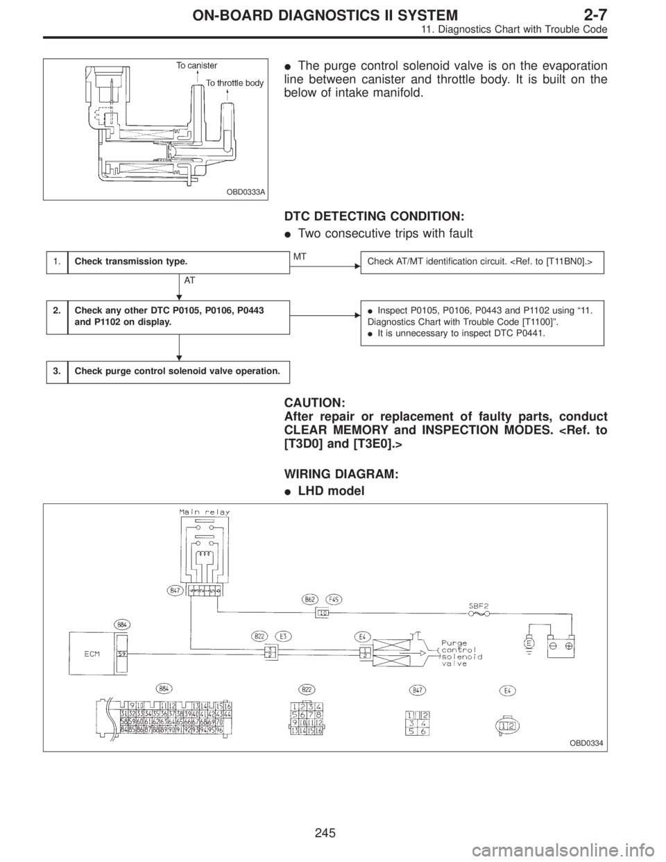
OBD0333A
�The purge control solenoid valve is on the evaporation
line between canister and throttle body. It is built on the
below of intake manifold.
DTC DETECTING CONDITION:
�Two consecutive trips with fault
1.Check transmission type.
AT
�MT
Check AT/MT identification circuit.
2.Check any other DTC P0105, P0106, P0443
and P1102 on display.��Inspect P0105, P0106, P0443 and P1102 using“11 .
Diagnostics Chart with Trouble Code [T1100]”.
�It is unnecessary to inspect DTC P0441.
3.Check purge control solenoid valve operation.
CAUTION:
After repair or replacement of faulty parts, conduct
CLEAR MEMORY and INSPECTION MODES.
[T3D0] and [T3E0].>
WIRING DIAGRAM:
�LHD model
OBD0334
�
�
245
2-7ON-BOARD DIAGNOSTICS II SYSTEM
11. Diagnostics Chart with Trouble Code
—
OBD0324A
DESCRIPTION:
The EGR solenoid valve is situated between the BPT and
EGR valve. EGR solenoid valve is opened")