Page 718 of 2248
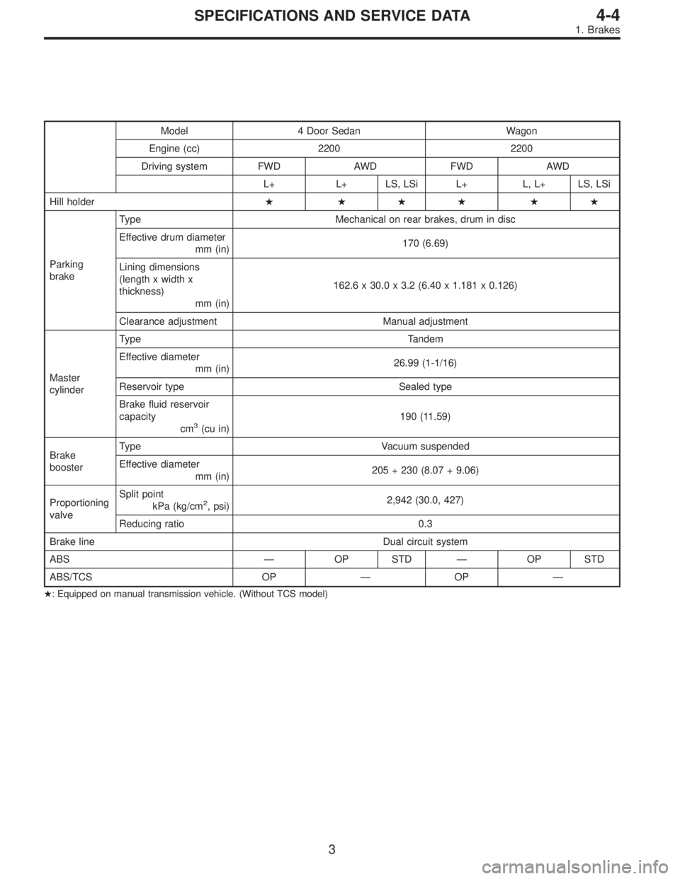
Model 4 Door Sedan Wagon
Engine (cc) 2200 2200
Driving system FWD AWD FWD AWD
L+ L+ LS, LSi L+ L, L+ LS, LSi
Hill holder� ��� ��
Parking
brakeType Mechanical on rear brakes, drum in disc
Effective drum diameter
mm (in)170 (6.69)
Lining dimensions
(length x width x
thickness)
mm (in)162.6 x 30.0 x 3.2 (6.40 x 1.181 x 0.126)
Clearance adjustment Manual adjustment
Master
cylinderType Tandem
Effective diameter
mm (in)26.99 (1-1/16)
Reservoir type Sealed type
Brake fluid reservoir
capacity
cm
3(cu in)190 (11.59)
Brake
boosterType Vacuum suspended
Effective diameter
mm (in)205 + 230 (8.07 + 9.06)
Proportioning
valveSplit point
kPa (kg/cm
2, psi)2,942 (30.0, 427)
Reducing ratio 0.3
Brake line Dual circuit system
ABS—OP STD—OP STD
ABS/TCS OP—OP—
�: Equipped on manual transmission vehicle. (Without TCS model)
3
4-4SPECIFICATIONS AND SERVICE DATA
1. Brakes
Page 720 of 2248
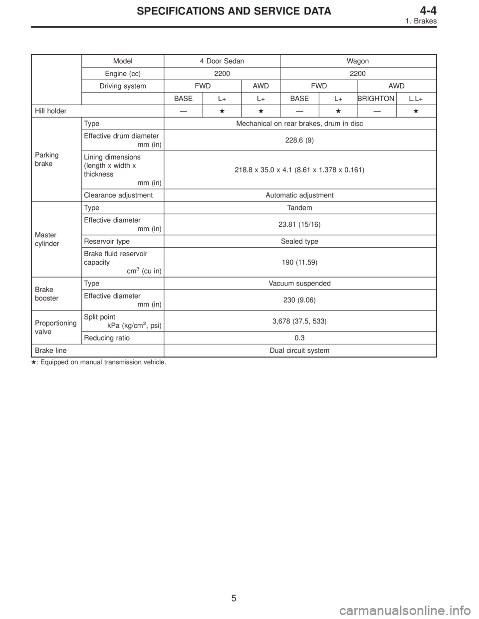
Model 4 Door Sedan Wagon
Engine (cc) 2200 2200
Driving system FWD AWD FWD AWD
BASE L+ L+ BASE L+ BRIGHTON L.L+
Hill holder—��—�—�
Parking
brakeType Mechanical on rear brakes, drum in disc
Effective drum diameter
mm (in)228.6 (9)
Lining dimensions
(length x width x
thickness
mm (in)218.8 x 35.0 x 4.1 (8.61 x 1.378 x 0.161)
Clearance adjustment Automatic adjustment
Master
cylinderType Tandem
Effective diameter
mm (in)23.81 (15/16)
Reservoir type Sealed type
Brake fluid reservoir
capacity
cm
3(cu in)190 (11.59)
Brake
boosterType Vacuum suspended
Effective diameter
mm (in)230 (9.06)
Proportioning
valveSplit point
kPa (kg/cm
2, psi)3,678 (37.5, 533)
Reducing ratio 0.3
Brake line Dual circuit system
�: Equipped on manual transmission vehicle.
5
4-4SPECIFICATIONS AND SERVICE DATA
1. Brakes
Page 785 of 2248
2. CHECKING THE HYDRAULIC UNIT OPERATION BY
PRESSURE GAUGE
1) Remove the FL and FR pipes from the hydraulic unit.
G4M0460
2) Connect two pressure gauges to the hydraulic unit.
CAUTION:
�Pressure gauges used exclusively for brake fluid
must be used.
�Do not employ pressure gauge previously used for
transmission since the piston seal is expanded which
may lead to malfunction of the brake.
3) Bleed air from the pressure gauges.
4) Perform sequence control.
B4M0082A
(1) Connect diagnosis terminals to 3 terminals (K) and
6 terminals (L) of the diagnosis connector beside driver
seat heater unit.
(2) Turn ignition switch ON.
(3) The ABS warning light comes on.
(4) Depress the brake pedal within 0.5 seconds after
the warning light goes out so that the pressure gauge
registers a pressure equal to the initial value.
CAUTION:
Do not depress the clutch pedal.
NOTE:
The engine must not be operating.
68
4-4SERVICE PROCEDURE
15. Hydraulic Unit for ABS System
Page 806 of 2248
 Lift-up vehicle and remove wheels.
2) Disconnect the air bleeder screws from the FL and F")
C: CHECKING THE HYDRAULIC UNIT ABS
OPERATION
1. CHECKING THE HYDRAULIC UNIT ABS
OPERATION BY PRESSURE GAUGE
1) Lift-up vehicle and remove wheels.
2) Disconnect the air bleeder screws from the FL and FR
caliper bodies.
B4M0633A
3) Connect two pressure gauges to the FL and FR caliper
bodies.
CAUTION:
�Pressure gauges used exclusively for brake fluid
must be used.
�Do not employ pressure gauge previously used for
transmission since the piston seal is expanded which
may lead to malfunction of the brake.
NOTE:
Wrap sealing tape around the pressure gauge.
4) Bleed air from the pressure gauges.
5) Perform ABS sequence control.
6) When the hydraulic unit begins to work, and first the FL
side performs decompression, holding, and compression,
and then the FR side performs decompression, holding,
and compression.
7) Read values indicated on the pressure gauge and
check if the fluctuation of the values between decompres-
sion and compression meets the standard values. Also
check if any irregular brake pedal tightness is felt.
Initial value When decompressed When compressed
Front wheel 3,432 kPa (35 kg/cm
2, 498 psi)490 kPa (5 kg/cm2, 71 psi)
or less981 kPa (10 kg/cm2, 142 psi)
or more
Rear wheel 3,432 kPa (35 kg/cm
2, 498 psi)490 kPa (5 kg/cm2, 71 psi) or
less981 kPa (10 kg/cm2, 142 psi)
or more
8) Remove pressure gauges and air bleeder screws from
the RL and RR caliper bodies.
9) Connect the air bleeder screws hose to the FL and FR
caliper bodies.
10) Connect two pressure gauges to the RL and RR cali-
per bodies.
11) Bleed air from the pressure gauges and the FL and FR
caliper bodies.
12) Perform ABS sequence control.
13) When the hydraulic unit begins to work, at first the RR
side performs decompression, holding, and compression,
and then the RL side performs decompression, holding,
and compression.
14) Read values indicated on the pressure gauges and
check if they meet the standard value.
87
4-4SERVICE PROCEDURE
20. Hydraulic Unit for ABS/TCS System
Page 812 of 2248
 Lift-up vehicle and remove wheels.
2) Disconnect the air bleeder screws from the FL and F")
E: CHECKING THE HYDRAULIC UNIT TCS
OPERATION
1. CHECKING THE HYDRAULIC UNIT TCS
OPERATION BY PRESSURE GAUGE
1) Lift-up vehicle and remove wheels.
2) Disconnect the air bleeder screws from the FL and FR
caliper bodies.
B4M0633A
3) Connect two pressure gauges to the FL and FR caliper
bodies.
CAUTION:
�Pressure gauges used exclusively for brake fluid
must be used.
�Do not employ pressure gauge previously used for
transmission since the piston seal is expanded which
may lead to malfunction of the brake.
NOTE:
Wrap sealing tape around the pressure gauge.
4) Bleed air from the pressure gauges.
5) Perform sequence control.
6) When the hydraulic unit begins to work, and first the FL
side performs compression, holding, and decompression,
and then the FR side performs compression, holding, and
decompression.
7) Read values indicated on the pressure gauge and
check if the fluctuation of the values between compression
and decompression meets the standard values. Also check
if any irregular brake pedal tightness is felt.
Initial value When compressed When decompressed
Front left wheel490 kPa (5 kg/cm
2, 71 psi)
or less1,471 kPa (15 kg/cm2, 213 psi)
or more490 kPa (5 kg/cm2, 71 psi)
or less
Front right wheel490 kPa (5 kg/cm
2, 71 psi)
or less1,471 kPa (15 kg/cm2, 213 psi)
or more490 kPa (5 kg/cm2, 71 psi)
or less
8) After checking, remove the pressure gauges from the
caliper bodies.
9) Connect the air bleeder screws to the FL and FR cali-
per bodies.
10) Bleed air from brake line.
93
4-4SERVICE PROCEDURE
20. Hydraulic Unit for ABS/TCS System
Page 922 of 2248
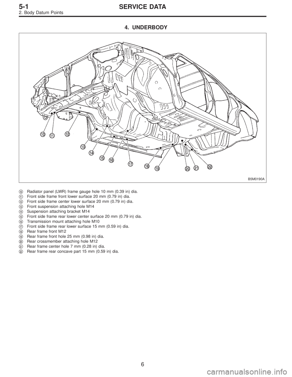
4. UNDERBODY
B5M0190A
�10Radiator panel (LWR) frame gauge hole 10 mm (0.39 in) dia.
�
11Front side frame front lower surface 20 mm (0.79 in) dia.
�
12Front side frame center lower surface 20 mm (0.79 in) dia.
�
13Front suspension attaching hole M14
�
14Suspension attaching bracket M14
�
15Front side frame rear lower center surface 20 mm (0.79 in) dia.
�
16Transmission mount attaching hole M10
�
17Front side frame rear lower surface 15 mm (0.59 in) dia.
�
18Rear frame front M12
�
19Rear frame front hole 25 mm (0.98 in) dia.
�
20Rear crossmember attaching hole M12
�
21Rear frame center hole 7 mm (0.28 in) dia.
�
22Rear frame rear concave part 15 mm (0.59 in) dia.
6
5-1SERVICE DATA
2. Body Datum Points
Page 1027 of 2248
 Remove bolts securing hinges (located at front of seat)
to body.
2) Pull strap (located in middle rear portion of cushion) to
release lock. Lift cushion out and away from bod")
G5M0350
2. WAGON MODEL
1) Remove bolts securing hinges (located at front of seat)
to body.
2) Pull strap (located in middle rear portion of cushion) to
release lock. Lift cushion out and away from body.
3) Pull knobs (located at each side of backrest’s upper
portion) up to release lock, and fold backrest all the way
forward.
B5M0333A
4) Remove the bolt�1and then remove backrest. (LH
side)
5) Remove the bolt�
2and then remove backrest (RH side)
from hinge bracket�
3.
G5M0348
G5M0345
B: INSTALLATION
1. SEDAN MODEL
1) Before installing backrest, ensure that trim panel, insu-
lator and seat belt are properly installed.
2) Transfer outer seat belt webbing to front of backrest and
fold backrest forward. Attach seat wire to upper hooks (2
places), and move pillow in the direction of“B”until back-
rest is aligned with lower mounting holes in body.
3) Engage backrest’s folding mechanism with striker.
4) Secure lower center and both sides of backrest to body
with bolts.
5) Slightly raise front section of cushion while pushing
down on cushion in the direction of“C”. With cushion held
in that position, attach rear section of cushion to hooks at
lower frame location.
6) Secure front of cushion to body with bolts.
CAUTION:
�Before installing seat, ensure that seat belt is placed
on cushion.
�Confirm that winding of three-point type seat belt
can operate regularly.
10
5-3SERVICE PROCEDURE
2. Rear Seat
Page 1071 of 2248
G6M0095
1. Starter
A: REMOVAL AND INSTALLATION
1) Disconnect battery ground cable.
G2M0309
2) Disconnect connector and terminal from starter.
3) Remove starter from transmission.
4) Installation is in the reverse order of removal.
Tightening torque:
50±4 N⋅m (5.1±0.4 kg-m, 36.9±2.9 ft-lb)
B: TEST
1. MAGNETIC SWITCH
CAUTION:
�The following magnetic switch tests should be per-
formed with specified voltage applied.
�Each test should be conducted within 3 to 5 sec-
onds. Power to be furnished should be one-half the
rated voltage.
B6M0415A
1) Pull-in test
Connect two battery negative leads onto magnetic switch
body and terminal C respectively. Then connect battery
positive lead onto terminal 50. Pinion should extend when
lead connections are made.
B6M0416A
2) Holding-in test
Disconnect lead from terminal C with pinion extended. Pin-
ion should be held in the extended position.
6
6-1SERVICE PROCEDURE
1. Starter

 Disconnect battery ground cable.
G2M0309
2) Disconnect connector and terminal from starter.
3) Remove starter from transmission.
4) Installation is in")