Page 422 of 2248
G3M0431
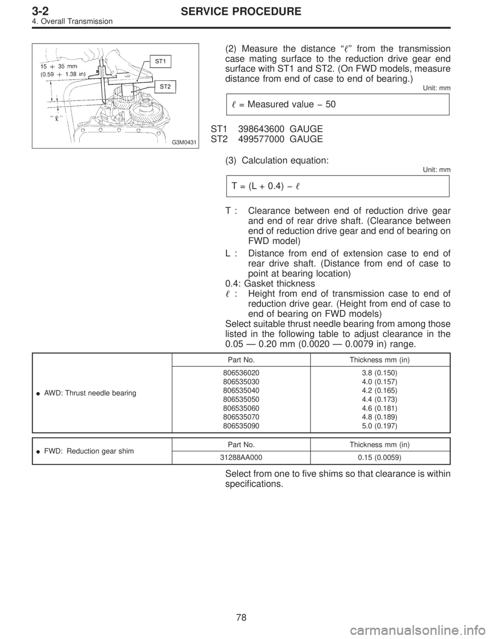
(2) Measure the distance“�”from the transmission
case mating surface to the reduction drive gear end
surface with ST1 and ST2. (On FWD models, measure
distance from end of case to end of bearing.)
Unit: mm
�= Measured value�50
ST1 398643600 GAUGE
ST2 499577000 GAUGE
(3) Calculation equation:
Unit: mm
T = (L + 0.4)��
T : Clearance between end of reduction drive gear
and end of rear drive shaft. (Clearance between
end of reduction drive gear and end of bearing on
FWD model)
L : Distance from end of extension case to end of
rear drive shaft. (Distance from end of case to
point at bearing location)
0.4: Gasket thickness
�: Height from end of transmission case to end of
reduction drive gear. (Height from end of case to
end of bearing on FWD models)
Select suitable thrust needle bearing from among those
listed in the following table to adjust clearance in the
0.05—0.20 mm (0.0020—0.0079 in) range.
�AWD: Thrust needle bearingPart No. Thickness mm (in)
806536020
806535030
806535040
806535050
806535060
806535070
8065350903.8 (0.150)
4.0 (0.157)
4.2 (0.165)
4.4 (0.173)
4.6 (0.181)
4.8 (0.189)
5.0 (0.197)
�FWD: Reduction gear shimPart No. Thickness mm (in)
31288AA000 0.15 (0.0059)
Select from one to five shims so that clearance is within
specifications.
78
3-2SERVICE PROCEDURE
4. Overall Transmission
Page 423 of 2248
G3M0896
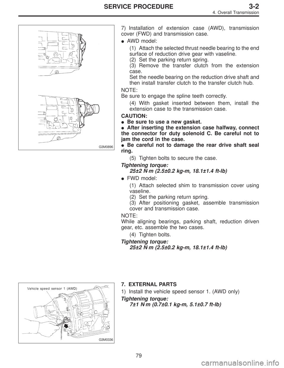
7) Installation of extension case (AWD), transmission
cover (FWD) and transmission case.
�AWD model:
(1) Attach the selected thrust needle bearing to the end
surface of reduction drive gear with vaseline.
(2) Set the parking return spring.
(3) Remove the transfer clutch from the extension
case.
Set the needle bearing on the reduction drive shaft and
then install transfer clutch to the transfer clutch hub.
NOTE:
Be sure to engage the spline teeth correctly.
(4) With gasket inserted between them, install the
extension case to the transmission case.
CAUTION:
�Be sure to use a new gasket.
�After inserting the extension case halfway, connect
the connector for duty solenoid C. Be careful not to
jam the cord in the case.
�Be careful not to damage the rear drive shaft seal
ring.
(5) Tighten bolts to secure the case.
Tightening torque:
25±2 N⋅m (2.5±0.2 kg-m, 18.1±1.4 ft-lb)
�FWD model:
(1) Attach selected shim to transmission cover using
vaseline.
(2) Set the parking return spring.
(3) After positioning gasket, assemble transmission
cover and transmission case.
NOTE:
While aligning bearings, parking shaft, reduction driven
gear, etc. assemble the two cases.
(4) Tighten bolts.
Tightening torque:
25±2 N⋅m (2.5±0.2 kg-m, 18.1±1.4 ft-lb)
G3M0336
7. EXTERNAL PARTS
1) Install the vehicle speed sensor 1. (AWD only)
Tightening torque:
7±1 N⋅m (0.7±0.1 kg-m, 5.1±0.7 ft-lb)
79
3-2SERVICE PROCEDURE
4. Overall Transmission
Page 424 of 2248
G3M0434
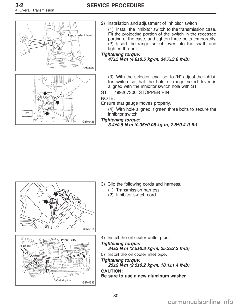
2) Installation and adjustment of inhibitor switch
(1) Install the inhibitor switch to the transmission case.
Fit the projecting portion of the switch in the recessed
portion of the case, and tighten three bolts temporarily.
(2) Insert the range select lever into the shaft, and
tighten the nut.
Tightening torque:
47±5 N⋅m (4.8±0.5 kg-m, 34.7±3.6 ft-lb)
G3M0435
(3) With the selector lever set to“N”adjust the inhibi-
tor switch so that the hole of range select lever is
aligned with the inhibitor switch hole with ST.
ST 499267300 STOPPER PIN
NOTE:
Ensure that gauge moves properly.
(4) With hole aligned, tighten three bolts to secure the
inhibitor switch.
Tightening torque:
3.4±0.5 N⋅m (0.35±0.05 kg-m, 2.5±0.4 ft-lb)
B3M0115
3) Clip the following cords and harness.
(1) Transmission harness
(2) Inhibitor switch cord
G3M0333
4) Install the oil cooler outlet pipe.
Tightening torque:
34±3 N⋅m (3.5±0.3 kg-m, 25.3±2.2 ft-lb)
5) Install the oil cooler inlet pipe.
Tightening torque:
25±2 N⋅m (2.5±0.2 kg-m, 18.1±1.4 ft-lb)
CAUTION:
Be sure to use a new aluminum washer.
80
3-2SERVICE PROCEDURE
4. Overall Transmission
Page 425 of 2248
G3M0332
6) Install the oil charge pipe.
Tightening torque:
Upper
41±3 N⋅m (4.2±0.3 kg-m, 30.4±2.2 ft-lb)
Lower
6.4±0.5 N⋅m (0.65±0.05 kg-m, 4.7±0.4 ft-lb)
CAUTION:
Be careful not to damage the O-ring.
G3M0348
7) Adjustment of brake band
(1) After tightening the brake band adjusting screw
with ST to 9 N⋅m (0.9 kg-m, 6.5 ft-lb) torque, back it off
three turns. Then secure with a lock nut.
ST 398603610 SOCKET WRENCH
Tightening torque:
26±2 N⋅m (2.7±0.2 kg-m, 19.5±1.4 ft-lb)
NOTE:
When tightening the lock nut, be careful not to turn the
adjusting screw.
B3M0114A
8) Install the air breather hose.
�
1Air breather hose (Transmission case)
�
2Air breather hose (Oil pump housing)
B3M0113
9) Install the pitching stopper bracket.
Tightening torque:
41±3 N⋅m (4.2±0.3 kg-m, 30.4±2.2 ft-lb)
81
3-2SERVICE PROCEDURE
4. Overall Transmission
Page 426 of 2248
G3M0325
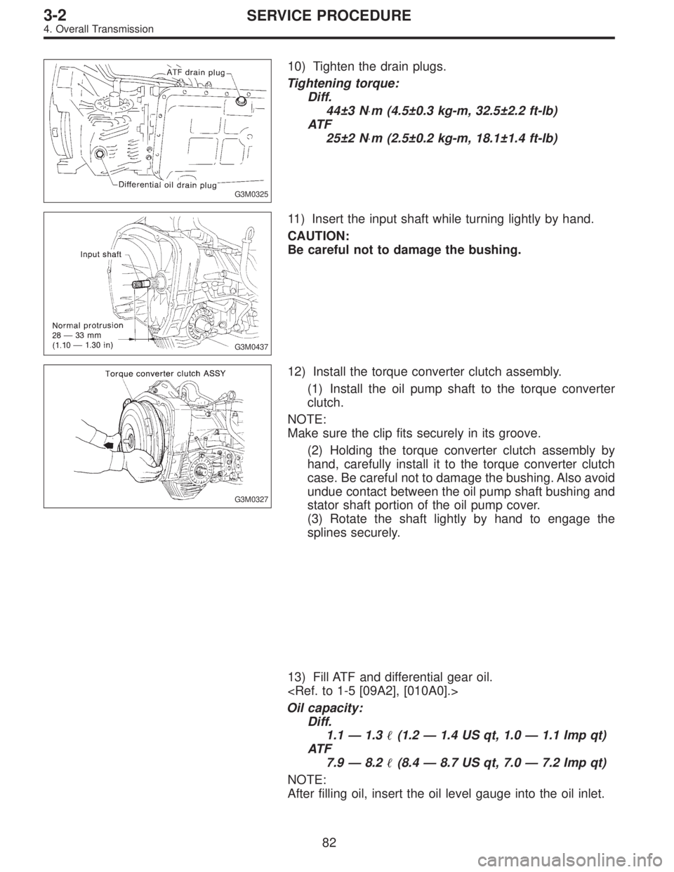
10) Tighten the drain plugs.
Tightening torque:
Diff.
44±3 N⋅m (4.5±0.3 kg-m, 32.5±2.2 ft-lb)
AT F
25±2 N⋅m (2.5±0.2 kg-m, 18.1±1.4 ft-lb)
G3M0437
11) Insert the input shaft while turning lightly by hand.
CAUTION:
Be careful not to damage the bushing.
G3M0327
12) Install the torque converter clutch assembly.
(1) Install the oil pump shaft to the torque converter
clutch.
NOTE:
Make sure the clip fits securely in its groove.
(2) Holding the torque converter clutch assembly by
hand, carefully install it to the torque converter clutch
case. Be careful not to damage the bushing. Also avoid
undue contact between the oil pump shaft bushing and
stator shaft portion of the oil pump cover.
(3) Rotate the shaft lightly by hand to engage the
splines securely.
13) Fill ATF and differential gear oil.
Oil capacity:
Diff.
1.1—1.3�(1.2—1.4 US qt, 1.0—1.1 Imp qt)
AT F
7.9—8.2�(8.4—8.7 US qt, 7.0—7.2 Imp qt)
NOTE:
After filling oil, insert the oil level gauge into the oil inlet.
82
3-2SERVICE PROCEDURE
4. Overall Transmission
Page 456 of 2248
G3M0493
15. Transfer Clutch
A: DISASSEMBLY
1) Remove the seal ring.
CAUTION:
Be careful not to damage the seal ring.
G3M0494
2) Using a press and ST, remove the ball bearing.
ST 498077000 REMOVER
CAUTION:
Do not reuse the bearing.
G3M0495
3) Remove the snap ring, and take out the pressure plate,
drive plates, and driven plates.
G3M0496
4) Remove the snap ring with ST1, ST2 and ST3, and take
out the spring retainer.
ST1 399893600 PLIERS
ST2 398673600 COMPRESSOR
ST3 498627000 SEAT
G3M0497
5) Apply compressed air to the rear drive shaft to remove
the piston.
109
3-2SERVICE PROCEDURE
15. Transfer Clutch
Page 457 of 2248
B: INSPECTION
1) Check the drive plate facing for wear and damage.
2) Check the snap ring for wear, return spring for perma-
nent set and breakage, and spring retainer for deformation.
3) Check the lathe cut ring for damage.
G3M0498
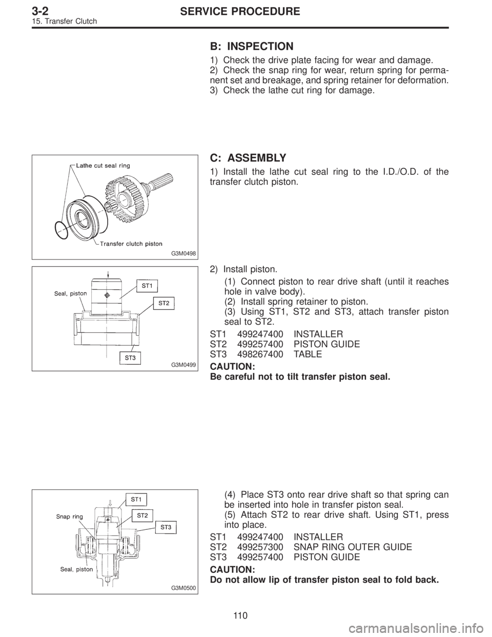
C: ASSEMBLY
1) Install the lathe cut seal ring to the I.D./O.D. of the
transfer clutch piston.
G3M0499
2) Install piston.
(1) Connect piston to rear drive shaft (until it reaches
hole in valve body).
(2) Install spring retainer to piston.
(3) Using ST1, ST2 and ST3, attach transfer piston
seal to ST2.
ST1 499247400 INSTALLER
ST2 499257400 PISTON GUIDE
ST3 498267400 TABLE
CAUTION:
Be careful not to tilt transfer piston seal.
G3M0500
(4) Place ST3 onto rear drive shaft so that spring can
be inserted into hole in transfer piston seal.
(5) Attach ST2 to rear drive shaft. Using ST1, press
into place.
ST1 499247400 INSTALLER
ST2 499257300 SNAP RING OUTER GUIDE
ST3 499257400 PISTON GUIDE
CAUTION:
Do not allow lip of transfer piston seal to fold back.
11 0
3-2SERVICE PROCEDURE
15. Transfer Clutch
Page 458 of 2248
G3M0501
3) Install the driven plates, drive plates, and pressure
plate, and secure with a snap ring with ST1, ST2 and a
press.
ST1 398673600 COMPRESSOR
ST2 498627000 SEAT
G3M0502
4) Apply compressed air to see if the assembled parts
move smoothly.
G3M0503
5) Check the clearance.
Standard value:
0.2—0.6 mm (0.008—0.024 in)
Allowable limit:
1.6 mm (0.063 in)
If the clearance is not within the specified range, select a
proper pressure plate.
NOTE:
Before measuring clearance, place the same thickness of
shim on both sides to prevent pressure plate from tilting.
�Available pressure platesPart No. Thickness mm (in)
31593AA151
31593AA161
31593AA171
31593AA1813.3 (0.130)
3.7 (0.146)
4.1 (0.161)
4.5 (0.177)
G3M0505
6) Press-fit the ball bearing with ST.
ST 899580100 INSTALLER
111
3-2SERVICE PROCEDURE
15. Transfer Clutch