Page 467 of 2248
G3M0683
6) Remove gearshift lever.
G3M0684
7) Remove the exhaust cover and remove cushion rubber
from the body.
G3M0685
B: DISASSEMBLY
1) Disconnect locking wires.
G3M0686
2) Remove rod from gearshift lever.
G3M0687
3) Disconnect snap ring.
7
3-3SERVICE PROCEDURE
1. Manual Transmission
Page 468 of 2248
G3M0688
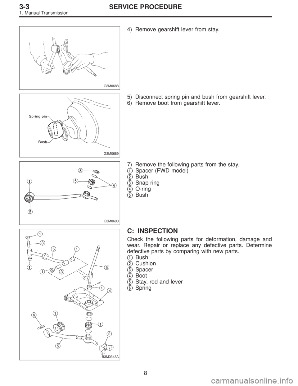
4) Remove gearshift lever from stay.
G3M0689
5) Disconnect spring pin and bush from gearshift lever.
6) Remove boot from gearshift lever.
G3M0690
7) Remove the following parts from the stay.
�
1Spacer (FWD model)
�
2Bush
�
3Snap ring
�
4O-ring
�
5Bush
B3M0343A
C: INSPECTION
Check the following parts for deformation, damage and
wear. Repair or replace any defective parts. Determine
defective parts by comparing with new parts.
�
1Bush
�
2Cushion
�
3Spacer
�
4Boot
�
5Stay, rod and lever
�
6Spring
8
3-3SERVICE PROCEDURE
1. Manual Transmission
Page 469 of 2248
G3M0692
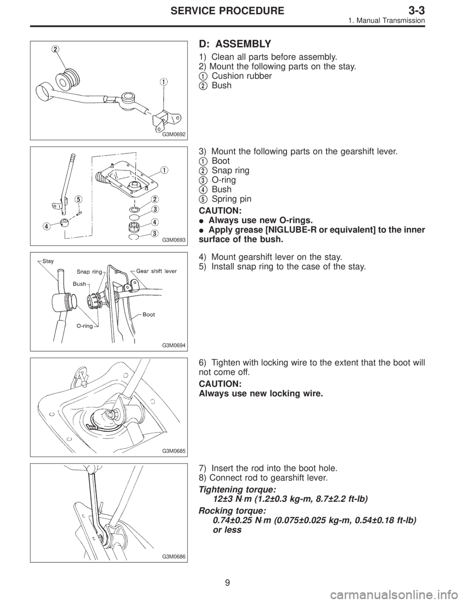
D: ASSEMBLY
1) Clean all parts before assembly.
2) Mount the following parts on the stay.
�
1Cushion rubber
�
2Bush
G3M0693
3) Mount the following parts on the gearshift lever.
�
1Boot
�
2Snap ring
�
3O-ring
�
4Bush
�
5Spring pin
CAUTION:
�Always use new O-rings.
�Apply grease [NIGLUBE-R or equivalent] to the inner
surface of the bush.
G3M0694
4) Mount gearshift lever on the stay.
5) Install snap ring to the case of the stay.
G3M0685
6) Tighten with locking wire to the extent that the boot will
not come off.
CAUTION:
Always use new locking wire.
G3M0686
7) Insert the rod into the boot hole.
8) Connect rod to gearshift lever.
Tightening torque:
12±3 N⋅m (1.2±0.3 kg-m, 8.7±2.2 ft-lb)
Rocking torque:
0.74±0.25 N⋅m (0.075±0.025 kg-m, 0.54±0.18 ft-lb)
or less
9
3-3SERVICE PROCEDURE
1. Manual Transmission
Page 470 of 2248
G3M0695
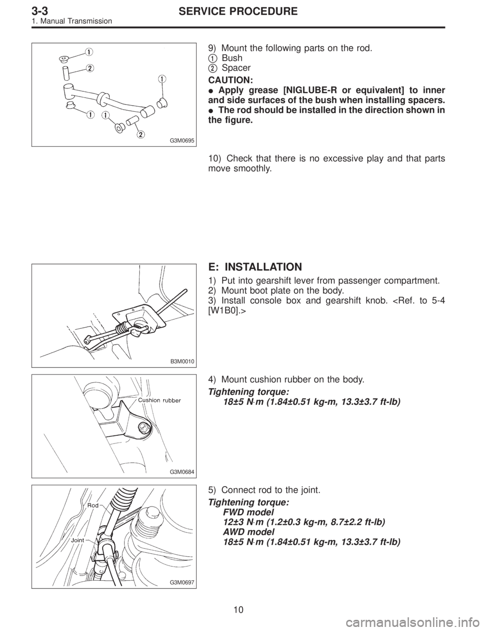
9) Mount the following parts on the rod.
�
1Bush
�
2Spacer
CAUTION:
�Apply grease [NIGLUBE-R or equivalent] to inner
and side surfaces of the bush when installing spacers.
�The rod should be installed in the direction shown in
the figure.
10) Check that there is no excessive play and that parts
move smoothly.
B3M0010
E: INSTALLATION
1) Put into gearshift lever from passenger compartment.
2) Mount boot plate on the body.
3) Install console box and gearshift knob.
[W1B0].>
G3M0684
4) Mount cushion rubber on the body.
Tightening torque:
18±5 N⋅m (1.84±0.51 kg-m, 13.3±3.7 ft-lb)
G3M0697
5) Connect rod to the joint.
Tightening torque:
FWD model
12±3 N⋅m (1.2±0.3 kg-m, 8.7±2.2 ft-lb)
AWD model
18±5 N⋅m (1.84±0.51 kg-m, 13.3±3.7 ft-lb)
10
3-3SERVICE PROCEDURE
1. Manual Transmission
Page 471 of 2248
G3M0681
6) Connect stay to the bracket.
Tightening torque:
18±5 N⋅m (1.84±0.51 kg-m, 13.3±3.7 ft-lb)
7) Install the exhaust cover.
G3M0698
2. Automatic Transmission
A: REMOVAL
1) Remove the cable.
(1) Prior to removal, set lever to“N”position.
(2) Remove front exhaust pipe.
G3M0699
(3) Separate cable from transmission lever.
(4) Remove clamp from transmission case.
B3M0102A
(5) Disconnect cable from selector lever and then
remove cable bracket.
G3M0702
2) Remove console box.
3) Disconnect the connectors.
11
3-3SERVICE PROCEDURE
1. Manual Transmission - 2. Automatic Transmission
Page 472 of 2248
G3M0681
6) Connect stay to the bracket.
Tightening torque:
18±5 N⋅m (1.84±0.51 kg-m, 13.3±3.7 ft-lb)
7) Install the exhaust cover.
G3M0698
2. Automatic Transmission
A: REMOVAL
1) Remove the cable.
(1) Prior to removal, set lever to“N”position.
(2) Remove front exhaust pipe.
G3M0699
(3) Separate cable from transmission lever.
(4) Remove clamp from transmission case.
B3M0102A
(5) Disconnect cable from selector lever and then
remove cable bracket.
G3M0702
2) Remove console box.
3) Disconnect the connectors.
11
3-3SERVICE PROCEDURE
1. Manual Transmission - 2. Automatic Transmission
Page 473 of 2248
G3M0703
4) Remove the screws to take off the plate from the body.
G3M0704
B: DISASSEMBLY
1) Remove grip from selector lever.
2) Remove indicator from plate.
B3M0346A
3) Remove the following parts from the grip.
�
1Button
�
2Spring
G3M0706
4) Remove shift-lock solenoid and“P”position switch.
G3M0707
5) Remove the bolt to take off the selector lever from the
plate and remove selector lever from the plate.
12
3-3SERVICE PROCEDURE
2. Automatic Transmission
Page 474 of 2248
 Remove lock plate.
7) Remove selector lever from the plate.
G3M0709
8) Remove detention spring.
C: INSPECTION
1) Inspect removed parts by comparing with new ones for
deformation, damage and")
G3M0708
6) Remove lock plate.
7) Remove selector lever from the plate.
G3M0709
8) Remove detention spring.
C: INSPECTION
1) Inspect removed parts by comparing with new ones for
deformation, damage and wear. Correct or replace if defec-
tive.
2) Confirm the following parts for operating condition
before assembly.
(1) Sliding condition of the button in the grip ... it should
move smoothly.
(2) Insertion of the grip on the selector lever ... when
pushing the grip on the selector lever by hand, screw
holes should be aligned.
(3) Operation of selector lever and rod ... they should
move smoothly.
(4) Insertion of the spacer into the selector lever ... it
should be inserted lightly by finger pressure.
G3M0707
D: ASSEMBLY
1) Clean all parts before assembly.
Apply grease [NIGLUBE-R or equivalent].
2) Assemble selector lever to the plate.
3) Insert the bolt and tighten the flange nut to the specified
torque.
Tightening torque (Flange nut):
12±3 N⋅m (1.2±0.3 kg-m, 8.7±2.2 ft-lb)
13
3-3SERVICE PROCEDURE
2. Automatic Transmission
 Remove gearshift lever.
G3M0684
7) Remove the exhaust cover and remove cushion rubber
from the body.
G3M0685
B: DISASSEMBLY
1) Disconnect locking wires.
G3M0686
2) Remove rod from gearshift")
 Connect stay to the bracket.
Tightening torque:
18±5 N⋅m (1.84±0.51 kg-m, 13.3±3.7 ft-lb)
7) Install the exhaust cover.
G3M0698
2. Automatic Transmission
A: REMOVAL
1) Remove the cable")
 Connect stay to the bracket.
Tightening torque:
18±5 N⋅m (1.84±0.51 kg-m, 13.3±3.7 ft-lb)
7) Install the exhaust cover.
G3M0698
2. Automatic Transmission
A: REMOVAL
1) Remove the cable")
 Remove the screws to take off the plate from the body.
G3M0704
B: DISASSEMBLY
1) Remove grip from selector lever.
2) Remove indicator from plate.
B3M0346A
3) Remove the following parts from")