Page 471 of 1701
EXTERIORLAMP
Front FogLamp/Wiring Diagram-F/FOG -
(Cont'd)
RHO MODELS FOREUROPE
•
Refer
talast page
(Fa ldaut page).
RIG.
ToEL-ILL
Refer
to
EL-POWER.
~~~
\!lSJ
GY'GY
"
n
B
BBB
1
i.l
1
- - -
~
lID[@]
B
FUSE
15A BLOCK
W
(JIB)
(EfOO)
~ (120)
R!L OR
II!'
I~I
(RONT
.
n
FOG LAMP
U
RELAY
t ~
~m
GY!L OR/B
117\,1~
~@)
GY/L
1-1-----
~ -----ell
FRONT
ILL FOG
LAMP
SWITCH ~ OR/BOR/B
I!\
FRONT
i!'1
FRONT
FOG
FOG
LAMP LAMP
LH RH
ll¥J~
~@9>
B B
I I
e----e
I I
B B
~ ~
EL-F/FOG-04
~
B
•
.---
•
B
m
!
1
JOINT
CONNECTOR-1
~
~ B
A~
T
L
LIGHTING
SWITCH
CEW
I
BATTERY
I
•
~10A
L:J
1361
B/R
rrf1D
ITIillIillITIIT
@
~ BR
HEL040
EL-99
Page 474 of 1701
EXTERIORLAMP
Rear FogLamp/Wiring Diagram-R/FOG -
WITH DAYTIME LIGHTSYSTEM
EL-R/FOG-01
RIG•
~E-ILL
REAR
ILL FOG
LAMP
SWITCH
@
RIG
rm
Refer
toEL-POWER.
W/PU.I'f;:---.- Next
"........ page
f.
B B
-!-
-!-
~ @D
I
BATTERY
I
•
~'-t3.5:.'----~'4~i
R
~
Irtn
"~ICHID
LIGHTING P
SWITCH
~
(£109)
JUNCTIONBOX
NO.2 (JOINT
11
2•
5
1
CONNECTORS)~
RI/Y r-PU/R~PU/R_PU/R~PU/R- -,
t
I
Ir
PU/RPPU/R
R/Y PU/R GYIR J
nTi1
m
a~W:i:II~AR ,
I~
FOG
n
LAMP
U
RELAY OFF
I!:iJI ~ ~ ~
I~JIIWI
B WIPU GY!L
TT
To
1--1
.. -:~~~: }~-F/F:~/R
+
EL-BUZZER
I
f
I
rn
JOINT CONNECTOR-3
~
~
B
I
f.
B B
-!- -!-
~ ~
r--------------------~
I
I
: ....
R%i5<=.-I ...........I-I1
(E~09)
I
L
~
~~
~BR
Refer
tolast page
(Foldout page).
I1IIIIIIIIIIlII ~
~BR
HEL042
EL-102
Page 476 of 1701
EXTERIORLAMP
Rear FogLamp/Wiring Diagram-R/FOG -
(Cont'd)
WITHOUT DAYTIMELIGHTSYSTEM
EL-R/FOG-03
REAR
ILL FOG
LAMP
SWITCH
~
LHO
models
RHO models
(b):
(8):
a
-I
m
CHID
P ~ P
P ~ P
m
CHID
a
1
~
,..,
a
B
~ ~
m
CHID
~PU/R~PU/R ~
I
I
O-ee-PU/R~PU/R~PU/R- ~Ot
r-
RIG
.~~-ILL
I ~
JUNCTIONBOX
II11JI
PPU~R
RIG
No.2 (JOINT
=r'
R/Y PU/R CONNECTORS)PU/R
mmm
141 ]llfEAA
FOG ~. INO
n
LAMP
U
RELAY
Ibi=U Ibi=JI ~
OFF
B W/PU ~~
L
BB
W/PU
o@>~:~~
PU/R.~-BUZZER
i--l
B
rn~
I
JOINT
5g~~~CTOR-3
@:
(b)
~ CONNECTOR-4
@:
(8)
B ~
I
BATTERY
I
•
.------rfl
RefertoEL-POWER.
[jt::1
Wi;,;i
R P
m ~~
LIGHTING
I__
SWITCH ~
~
(fl09)
r--------------------,
I
L ~
~~
T
L
[JQII~
~aR
Refer
tolast page
(Foldout page).
IIIIIillJIlIIil ~:
IIIIIillJIlIIil ~:
~~ ~P
HEL044
EL-104
Page 505 of 1701

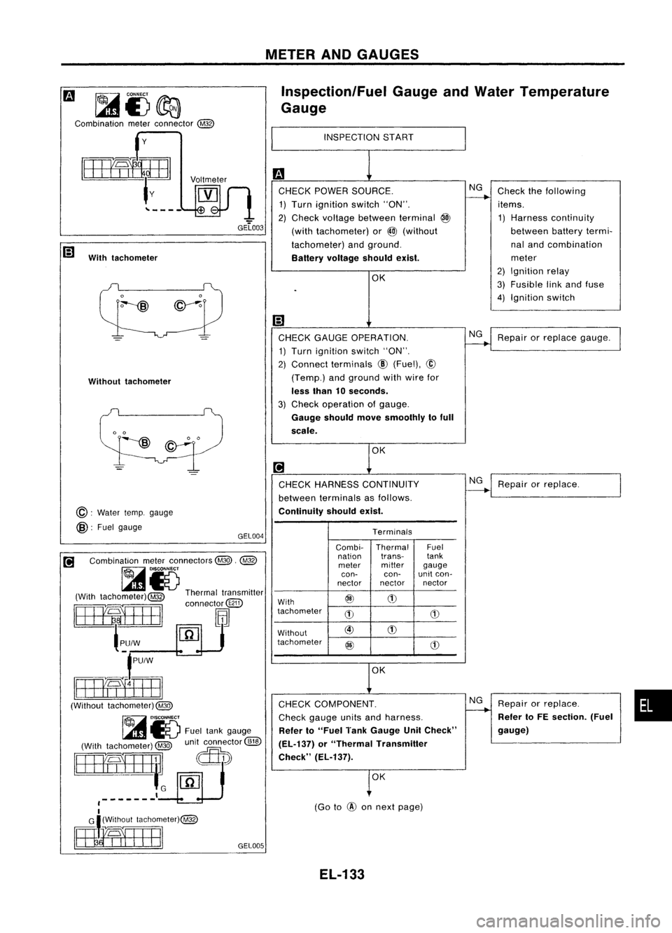
METERANDGAUGES
~i5~
Combination meterconnector @ Inspection/Fuel
GaugeandWater Temperature
Gauge
y
INSPECTION
START
With tachometer
•
Repair
orreplace.
Refer toFE section. (Fuel
gauge)
Repair
orreplace gauge.
Check
thefollowing
items.
1) Harness continuity
between batterytermi-
nal and combination
meter
2) Ignition relay
3) Fusible linkand fuse
4) Ignition switch
NG
NG
~ Repair orreplace.
(Go to
@
onnext page)
OK
OK
CHECK COMPONENT. NG
Check gauge unitsandharness.
Refer to"Fuel TankGauge UnitCheck"
(EL-137) or"Thermal Transmitter
Check" (EL-137).
CHECK
GAUGE OPERATION.
1) Turn ignition switch"ON".
2) Connect terminals @(Fuel), @
(Temp.) andground withwire for
less than 10seconds.
3) Check operation ofgauge.
Gauge should movesmoothly tofull
scale.
CHECK HARNESS CONTINUITY
between terminals asfollows.
Continuity shouldexist.
CHECK
POWER SOURCE.
1) Turn ignition switch"ON".
2) Check voltage between terminal @
(with tachometer) or
@
(without
tachometer) andground.
Battery voltage shouldexist.
Terminals
Combi- Thermal Fuel
nation trans-
tank
meter miller
gauge
con- can-unit
con-
nector nector nectar
With @
(1)
tachometer
d) d)
Without @
(1)
tachometer @
d)
GEL005
GEL004
Voltmeter
Without tachometer
@:
Water temp.gauge
@:
Fuelgauge GEL003
[!J Combination meterconnectors @.@
~15 .
(With tachometer)@ Thermaltransmitter
rttEEifIEBl
connect~@TI)
{~u;:J9J
f
pu/
w
smma
(Without tachometer)@
~ DISCONNECT
l..m
IV Fueltank gauge
(With tachometer)
@
unitconnector
@ID
~]~rr
Lcru
I
,-------
I
mimEr")~
EL-133
Page 506 of 1701

METERANDGAUGES
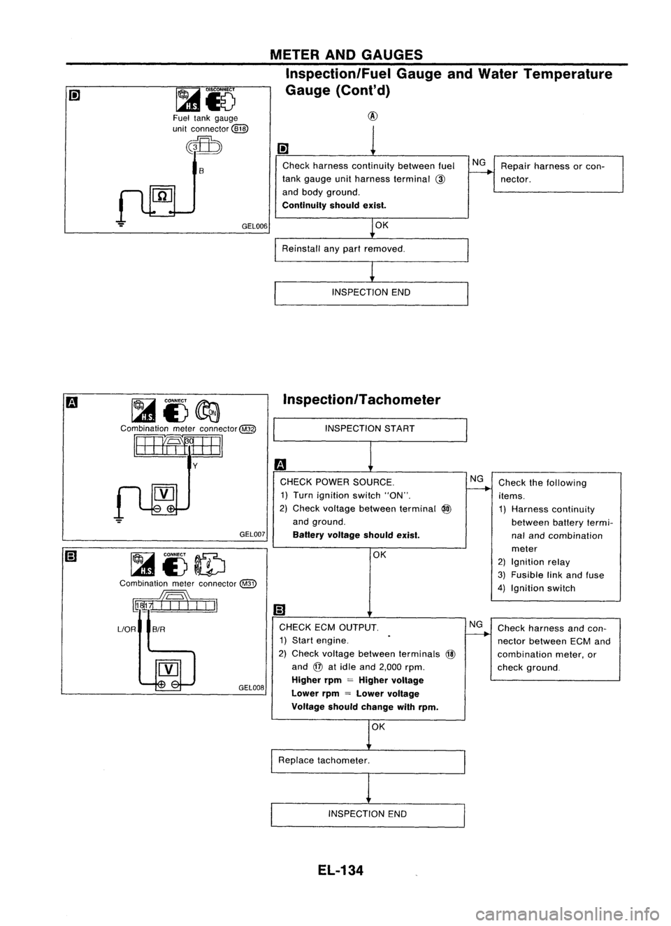
Inspection/Fuel GaugeandWater Temperature
Gauge (Cont'd)
Fuel tank gauge
unit connector
@W
~
S
GEL006
~i)~
Combination meterconnector@
8mIIEJ
y
GEL007
~i3ID
Combination meterconnector
@
w1i7h:n
Check
harness continuity betweenfuel
tank gauge unitharness terminal
@
and body ground.
Continuity shouldexist.
OK
Reinstall anypart removed.
INSPECTION END
Inspection/Tachometer
INSPECTION START
m
CHECK POWER SOURCE.
1) Turn ignition switch"ON".
2) Check voltage between terminal
@
and ground.
Battery voltage shouldexist.
OK NG
NG
Repair
harness orcon-
nector.
Check thefollowing
items.
1) Harness continuity
between batterytermi-
nal and combination
meter
2) Ignition relay
3) Fusible linkand fuse
4) Ignition switch
LlOR
SIR
GEL008
CHECK
ECMOUTPUT. NG
1) Start engine.
2) Check voltage between terminals
@
and
@
atidle and 2,000 rpm.
Higher rpm
=
Higher voltage
Lower rpm
=
Lower voltage
Voltage shouldchange withrpm.
Replace tachometer.
INSPECTION END
EL-134
Check
harness andcon-
nector between ECMand
combination meter,or
check ground.
Page 541 of 1701

WIPERANDWASHER
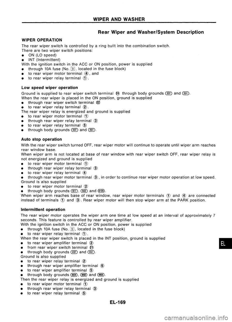
Rear Wiper andWasher/System Description
WIPER OPERATION
The rear wiper switch iscontrolled byaring built intothecombination switch.
There aretwo wiper switch positions:
• ON (LO speed)
• INT (Intermittent)
With theignition switchinthe ACC orON position, powerissupplied
• through 10Afuse (No.
W,
located inthe fuse block)
• torear wiper motorterminal
@,
and
• torear wiper relayterminal
CD.
Low speed wiperoperation
Ground issupplied torear wiper switch terminal
@
through bodygrounds
@
and
Cill).
When therear wiper isplaced inthe ON position, groundissupplied
• through rearwiper switch terminal
@
• torear wiper relayterminal
@.
The rear wiper relayisenergized andground issupplied
• torear wiper motor terminal
CD
• through rearwiper relayterminal
CID
• torear wiper relayterminal
CID
• through bodygrounds
@
and
Cill).
Auto stopoperation
With therear wiper switch turned OFF,rearwiper motor willcontinue tooperate untilwiper armreaches
rear window base.
When wiperarmisnot located atbase ofrear window withrearwiper switch OFF,rearwiper relayis
not energized andground issupplied
• torear wiper motorterminal
CD
• through rearwiper relayterminal
CID
• torear wiper relayterminal
@
• through rearwiper motor terminal
CID,
inorder tocontinue rearwiper motoroperation atlow speed.
Ground isalso supplied
• torear wiper motor terminal
@
• through bodygrounds
Cill),
@
and
(Qill).
When wiperarmreaches baseofrear window, rearwiper motorterminals
CD
and
@
are connected
instead ofterminals
CD
and
CID.
Rear wiper motor willthen stopwiper armatthe PARK position.
Intermittent operation
The rear wiper motor operates thewiper armonetime atlow speed atan interval ofapproximately 7
seconds. Thisfeature iscontrolled byrear wiper amplifier.
With theignition switchinthe ACC orON position, powerissupplied
• through 10Afuse (No.
W,
located inthe fuse block)
• torear wiper relayterminal
CD.
When therear wiper switch isplaced inthe INT position, groundissupplied •
• torear wiper amplifier terminal
@
• from rearwiper switch terminal
@
• through bodygrounds
@
and
Cill).
Ground isalso supplied
• torear wiper relayterminal
@
• through rearwiper amplifier terminal
@
• torear wiper amplifier terminal
CID
• through bodygrounds
@,
@ID
and
@.
Then therear wiper relayisenergized andground issupplied
• torear wiper motorterminal
CD
• through rearwiper relayterminal
CID
• torear wiper relayterminal
CID
EL-169
Page 544 of 1701
WIPERANDWASHER
Rear Wiper andWasher/Wiring Diagram
- WIP/R -(Cont'd)
EL-WIP/R-02
1--
1•
B
~@Qg)
ICiJI@
B
I
I.
B B
~ ~
t
B
m
~
(0101)
SB~SB
~
Y!L
I I
t
OR ~ Y!L
~----$
OR
@)
Y!L
I I
OR
@)
Y!L
I$~ -
~1-
iclJl
OR ~ Y!L
..-J
SB OR
111 ~~rEAR
WIPER
RELAY
1!:i=Jl1biJl4Jl
{~
SB
~ SB----.
Preceding
page
L/WBY/L
Preceding
---15l-
L7;-----'
I
page ~
I.
B B
~ ~
~ (E51)
fIlii'
I'~
45678 W~
(E15)
T
B
~
(E117)
~W
~
(0106)
~W
HEL091
EL-172
Page 546 of 1701
WIPERANDWASHER
Rear Wiper andWasher/Wiring Diagram
- WIP/R -
(Co nt'd)
EL-WIP/R-04
1---
B
ffi@
+@
B
I
f.
B BB
~ ~
.....
mD@~
t
REAR
-- t
WIPER
MOVE MOTOR
<[l106)
I
SB
m
ILi=ll
Y/L
I I
t
OR
@QD
Y/L
1Fh----m
T~T
OR Y/L
...L(]ID...L
11.llJ~ --- -il1,gJl
-.-@ -.-
OR Y/L
...LCBID...L
1l6QJ1- --- -
i~1
=r~
OR Y/L
r---I
~
@QD
SB~SB
SB OR
II!I ~rAA
WIPER
RELAY
1bjJI1bj:JI4=JI
L/W BY/L
~L~
I
I
f.
B B
~ ~
rn
@D
Preceding
{
SB
page
~SB
Preceding
page
fH!/'
I
Ill!
@QD ~
<[l106)
45678 W~ W
Refer
tolast page
(Foldout page).
~@
T
B
HEL093
EL-174