Page 597 of 1701
ELECTRICSUNROOF
Wiring Diagram -SROOF -(ConI' d)
Preceding ...........
A1.
1
page ~
L/W@)
~
L/W
EL-SROOF-02
SUN ROOF MOTOR ASSEMBLY
OOWN/OPEN- -UP/CLOSE
M
UPjCLOSE
RELAY DOWN/OPEN
RELAY
TILT SW SLIDESW
TILTSW
LIMIT LIMIT
SWITCH SWITCH
OTHER
-1
-2
---
--_
...
----
FULL
FULLFULL
FULL
CLOSED TILT-UPOPEN
TILT-DOWN
SLIDE
SWITCH SUN
ROOF
SWITCH
g@)
L1.J
W
•
HEL 131
EL-225
Page 598 of 1701
HORN,CIGARETTE LIGHTERANDCLOCK
Wiring Diagram -HORN -
LHD MODELS
EL-HORN-01
HORN
SWITCH
SPIRAL
CABLE
Models
without
air bagsystem
Models withdual
air bagsystem
Models withsingle
air bagsystem
8 *2
AIR BAG
DIAGNOSIS
SENSOR
UNIT
.......
_-.",.
RE-
LEASED
@:
@:
@:
HORN
SWITCH
SPIRAL
CABLE
em
'---"
RE-
LEASED
G/Y
m~
BATTERY
]
10A RefertoEL-POWER.
1421
G/B
g
2
HORN
~ RELAY
~1bjJl@
G G/Y
I----,O'----O~:------I
AN
!
~ G/Y
G /Y
r:::!::.
11tJ1~
11711
G/Y
......,~
I!:i=ll@
G/Y
~
T'---I
G G
QJ1 QJ1
HORN HORN
(LOW) (HIGH)
~ ~
ffim
[ill]
W
@
W
I:I[Q:TI:ICID
~W
DIDdZl
~BR
Refer
tolast page
(Foldout page).
FI ~ ~
(ffiJ)
L!J
B'B 'B
~*1
c:IIJgI
B
~*2
~W
HEL132
EL-226
Page 600 of 1701
HORN,CIGARETTE LIGHTERANDCLOCK
Wiring Diagram -HORN -(ConI' d)
RHO
MODELS
EL-HORN-03
HORN
SWITCH
SPIRAL
CABLE
Models
without
air bagsystem
Models withdual
air bagsystem
Models withsingle
air bagsystem
B *2
AIR BAG
DIAGNOSIS
SENSOR
UNIT
.......
_-"
RE-
LEASED
@:
@:
@:
HORN
SWITCH
SPIRAL
CABLE
ill)
......
_-"
RE-
LEASED
G/Y
m
G/B
g
2
HORN
~ RELAY
~4=HID
G G/Y
I----IO----.O~ ..
------I
AN. G/Y
G/Y ~
~~ Ifill
I~I
G/Y
1~IU6~
G/Y
rn
'---I
G G
QJ1 QJ1
HORN HORN
(LOW) (HIGH)
m rn
mID
[ill]
W
@
W
~
ill)
DID"JZl
108)
~W ~BR
Refer
tolast page
(Fo ldout page).
F.1
rn m
l..!.J
B' B'B
~
*1
IT:I::illl
8
~*2
~W
HEL134
EL-228
Page 602 of 1701

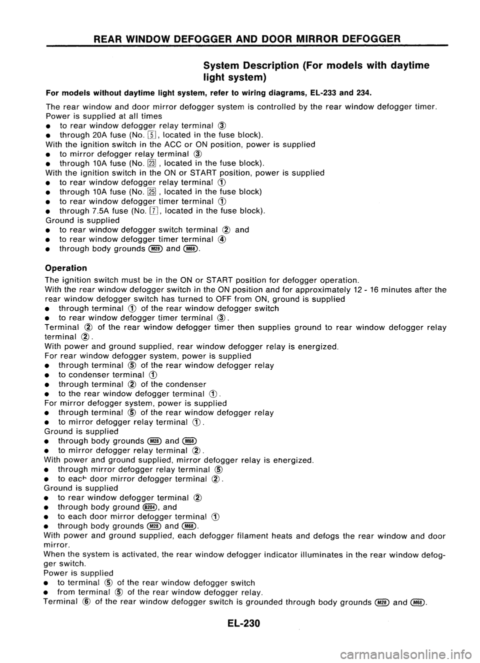
REARWINDOW DEFOGGER ANDDOOR MIRROR DEFOGGER
System Description (Formodels withdaytime
light system)
For models withoutdaytime lightsystem, refertowiring diagrams, EL-233and234.
The rear window anddoor mirror defogger systemiscontrolled bythe rear window defogger timer.
Power issupplied atall times
• torear window defogger relayterminal
@
• through 20Afuse (No.[[],located inthe fuse block).
With theignition switchinthe ACC orON position, powerissupplied
• tomirror defogger relayterminal
@
• through 10Afuse (No.
InJ,
located inthe fuse block).
With theignition switchinthe ONorSTART position, powerissupplied
• torear window defogger relayterminal
CD
• through 10Afuse (No.
[2ID,
located inthe fuse block)
• torear window defogger timerterminal
CD
• through 7.5Afuse(No.[[],located inthe fuse block).
Ground issupplied
• torear window defogger switchterminal
@
and
• torear window defogger timerterminal
@
• through bodygrounds
@
and
@ID.
Operation
The ignition switchmustbeinthe ONorSTART position fordefogger operation.
With therear window defogger switchinthe ONposition andforapproximately 12-16 minutes afterthe
rear window defogger switchhasturned toOFF from ON,ground issupplied
• through terminal
CD
ofthe rear window defogger switch
• torear window defogger timerterminal
@.
Terminal
@
ofthe rear window defogger timerthensupplies groundtorear window defogger relay
terminal
@.
With power andground supplied, rearwindow defogger relayisenergized.
For rear window defogger system,powerissupplied
• through terminal
CID
ofthe rear window defogger relay
• tocondenser terminal
CD
• through terminal
@
ofthe condenser
• tothe rear window defogger terminal
CD.
For mirror defogger system,powerissupplied
• through terminal
CID
ofthe rear window defogger relay
• tomirror defogger relayterminal
CD.
Ground issupplied
• through bodygrounds
@
and
@ID
• tomirror defogger relayterminal
@.
With power andground supplied, mirrordefogger relayisenergized.
• through mirrordefogger relayterminal
CID
• toeac
r
doormirror defogger terminal
@.
Ground issupplied
• torear window defogger terminal
@
• through bodyground
and
• toeach doormirror defogger terminal
CD
• through bodygrounds
@
and
@ID.
With power andground supplied, eachdefogger filamentheatsanddefogs therear window anddoor
mirror.
When thesystem isactivated, therear window defogger indicatorilluminates inthe rear window defog-
ger switch.
Power issupplied
• toterminal
CID
ofthe rear window defogger switch
• from terminal
CID
ofthe rear window defogger relay.
Terminal
@
ofthe rear window defogger switchisgrounded throughbodygrounds
@
and
@.
EL-230
Page 604 of 1701

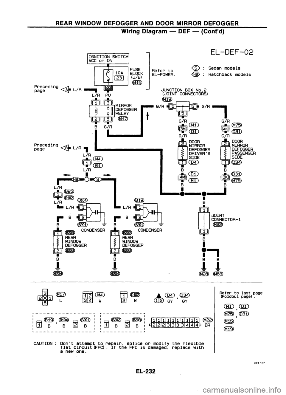
REARWINDOW DEFOGGER ANDDOOR MIRROR DEFOGGER
Wiring Diagram -DEF -(Cont'd)
JUNCTION BOXNo.2
(JOINT CONNECTORS)
G/R?G/R-'
EL-DEF-02
Sedan models
Hatchback models
@:
@:
G/R
IUT\
G/RIG=7c:\
~\.Mi.J ~~
1~1
([D
I~l
@)
G/R G/R
(J)
~RAOA
m~~~
DEFOGGER
DEFOGGER
DRIVER'S PASSENGER
SIDE SIDE
ClJC@ ClJ@)
B B
IrtJl ~~~ ~ 1$1~~~
B B
____ I&__
le__ '
•
B
(1J
1
JOINT
CONNECTOR-1
~
~ B
I
"
a
a
!- !-
~~
Refer
to
EL-POWER.
t
FUSE
BLOCK
(JIB)
~
Preceding ~L/R
1~31
page ~.....
L/R PU
I
1
1
1~IIMrRAOA
n
DEFOGGER
U
RELAY
Ibi=U ~
@)
B
G/R
I
Preceding ~L/R
page ~,
L/R
IU'7"\
~0:M.I
ICIJI(]I)
L/R
..... I~...
~O
~S:-"
L/R
ctI@
~
IFifOA\
1619'
L/R ~
IE!.!3I
... L/R ~ L/R~
r- B~1 r-B~1
B ~
=
B
@QD -
m ~
~NSER
I:j:'l ~
CO~SER
REAR REAR
WINDOW WINDOW
DEFOGGER DEFOGGER
IbjJ ~
Ibi=JI~
B B
-!
!-
~ ~
r---------------, ~-----------,
I II I
I ~ ~ ~II ~ ~I
ITIIIII.TIII:TI ~
:[jjB'B (gjB::rTIB @lB:~BR
I II I
L
~~ ~
+
2 1 L
5
FmlaID
001
W
.C@,~
GY GY
Refer
tolast page
(Fo ldout page).
CBD
(ill)
,
~@
~
CAUTION: Don'tattempt torepair. spliceormodify theflexible
flat circuit (FFC).
If
the FFC isdamaged, replacewith
a new one.
HEL137
EL-232
Page 638 of 1701
LOCATIONOFELECTRICAL UNITS
Engine Compartment
Front wiper motor (LHDmodels)
Fusible linkand relay box ASS
relay boxand actuator (RHOmodels)
Front wiper motor (RHOmodels)
Glow relay(CDengine models)
Fusible linkand fuse box
Cooling fan
relay-2 Rear
foglamp relay
• Cooling fanrelay-3 (SRengine
AT models andCDengine)
Rear window defogger relay
(GA engine withdaytime lightsystem)
EL-266 Fusible
linkand fuse box
Fusible linkand relay box
Rear window defogger relay
(CD engine withdaytime lightsystem)
HEL149
Page 639 of 1701
LOCATIONOFELECTRICAL UNITS
Passenger Compartment
LHD MODELS
Rearwindow defogger timer
(With daytime lightsystem)
Warning buzzerunit
Combination flasherunit
Junction boxNO.2 (Joint connectors)
Stop lamp switch
Mirror defogger relay
(With daytime lightsystem)
Sun roofrelay (Without powerwindow)
Power window relay(With power window)
Front foglamp relay
SMJ (Main harness-
engine roomharness) NATS
IMMU (Gasoline engine)
Door locktimer
ABS control unit
Front wiper amplifier
SMJ (Main harness-
front doorharness)
SMJ (Main harness-
front doorharness)
Rear wiper amplifier
Daytime lightunit
Circuit breaker
Fuel pump relay
(Gasoline engine)
Fuse block
(JIB)
Ignition relay
Blower relay
Accessory relay Air
bag diagnosis sensorunit
(With dualairbag system)
ECM (ECCS control module) (Gasoline engine)
ECM (Engine controlmodule) (Dieselengine)
ECCS relay(Gasoline engine)
EL-267 HEL
150
•
Page 640 of 1701
RHOMODELS LOCATION
OFELECTRICAL UNITS
Passenger Compartment (Cont'd)
Warning buzzerunit
ABS control unit
Front wiper amplifier
SMJ (Main harness-
front doorharness) NATS
IMMU (Gasoline engineforEurope)
Rear wiper amplifier
Combination flasherunit
Stop lamp switch
Sun roolrelay (Without powerwindow)
Power window relay(With power window)
Front foglamp relay
SMJ (Main harness-
engine roomharness)
EGM (EGGS controlmodule) (Gasoline engine)
EGM (Engine controlmodule) (Dieselengine)
EGGS relay(Gasoline engine)
EL-268 SMJ
(Main harness-
Iront doorharness)
Circuit breaker
Fuel pump relay
(Gasoline engine)
Fuse block
(JIB)
Accessory relay
Blower relay
Ignition relay
HEL151