1995 NISSAN ALMERA N15 relay
[x] Cancel search: relayPage 1450 of 1701
TROUBLEDIAGNOSES
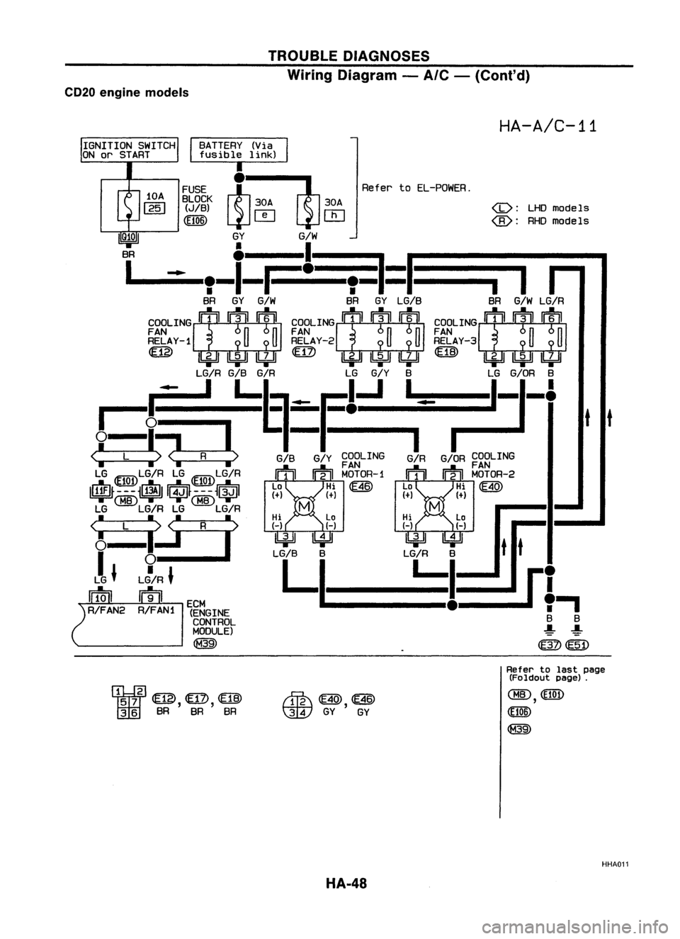
Wiring Diagram -
A/C -
(Cont'd)
CD20 engine models
HA-A/C-11
IGNITION SWITCH
ON or START
:
LHDmode 1s
@:
RHDmodels
tt
I
I
BR G/WLG/R
COOLING1:}:1
:!J'
I~II
FAN
nn
RELAY-3
UU
((@
I'=idI
IliJI~
LG G/OR B
1--1
FUSE
r1!Jj;1]
RefertoEL-POWER.
10A BLOCK 30A30A
1251
(J/B)
(Et06)
0
[B]
GY G/W
1---1
_ ....-,-I-F.
,-1=
BR GYG/W BRGYLG/B
COOLING1:Jt1 1::11
I~II
COOLING
1
:!: ::JI
::II
FAN
nn
FAN
nn
RELAY-1
UU
RELAY-2
UU
llli>
I'=idI
IliJI ~ ~
I'=idI
Iki=ll~
LG/R G/BG/R LGG/Y B
~ 1-1_
I..J
1_
r~-CJI::~.
971~
G/BG/YCOOLING
<;::J:=;> ~
dbdbFAN
LG Ifii\i\LG/R LGIfii\i\LG/R II111 II2 II MOTOR-1
,..,Ib ~ ~
r::::!=~ r::::!=
LaHi
IE"4S
~-M-a-~ "1rlt-M-a-iI3.r1l (+)(+)~
LG
CHID
LG/R LG
CHID
LG/R
M
~£:r
HiHi
O~I.
R
ijl ijl
I
0
LG/BB LG/RB
tt
LG
t
L:/R
t
LI
L...I
r'
IFffill
m
ECM _,
1.____...,
R/FAN2 R/FAN1 (ENGINE
CONTROL BB
MODULE)
-!--!-
@
~ llli>,@,((@
~BR BRBR
~@,~
~ GYGY
Refer
tolast page
(Foldout page).
CHID
(EiOt)
,
~
HHA011
HA-48
Page 1456 of 1701
TROUBLEDIAGNOSES
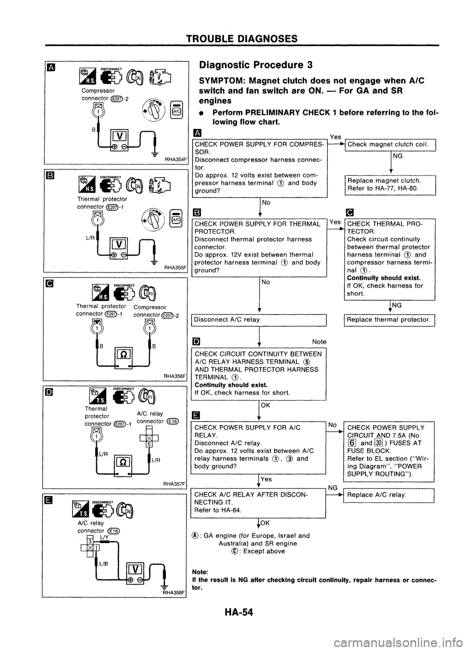
Diagnostic Procedure3
SYMPTOM: Magnetclutchdoesnotengage when
Ale
switch andfanswitch areON. -For GAand SR
engines
• Perform PRELIMINARY CHECK1before referring tothe fol-
lowing flowchart.
Replacemagnetclutch.
Refer toHA-77, HA-80.
Check
magnet clutchcoil.
NG
Yes
m
CHECK POWER SUPPLY FORCOMPRES-
SOR. Disconnect compressor harnessconnec-
tor. Do approx. 12volts existbetween com-
pressor harness terminal
ill
and body
ground?
RHA354F
s
Compressor
connector
@QD-2
~
RHA357FRHA356F
NG
CHECK POWER SUPPLY
CIRCUIT AND7.5A(No.
[Q]
and ~)FUSES AT
FUSE BLOCK.
Refer toEL section ("Wir-
ing Diagram", "POWER
SUPPLY ROUTING").
Replace AICrelay.
I
Replace thermalprotector.
[;J
Yes CHECK THERMAL PRO-
TECTOR.
Check circuit continuity
between thermalprotector
harness terminal
ill
and
compressor harnesstermi-
nal
ill.
Continuity shouldexist.
If OK, check harness for
shorl.
No
NG
CHECK
CIRCUIT CONTINUITY BETWEEN
AIC RELAY HARNESS TERMINAL @
AND THERMAL PROTECTOR HARNESS
TERMINAL
ill.
Continuity shouldexist.
If OK, check harness forshorl. Note
Yes
CHECK
POWER SUPPLY FORAIC
RELAY.
Disconnect AICrelay.
Do approx. 12volts exist!)etween AIC
relay harness terminals
ill,
@
and
body ground?
CHECK AICRELAY AFTER DISCON-
NECTING IT.
Refer toHA-64.
Disconnect
AICrelay. NoNo
[;)
CHECK POWER SUPPLY FORTHERMAL
PROTECTOR.
Disconnect thermalprotector harness
connector. Do approx. 12Vexist between thermal
protector harnessterminal
ill
and body
ground?
OK
@:
GAengine (forEurope, Israeland
Australia) andSRengine
@:
Except above
RHA355F
~ i5@a
Thermal protector
AIC
relay
connector
@-1
connector
(ill)
,"R~~t
[1[]
lIR
lIR
Thermal
protector
connector
@QD-1
~
Thermal protector Compressor
connector
@QD-1
connector
@QD-2
~ ~
~ ~ ls
~
~15~
AlC relay
connector
(ill)
~lIY
RHA358FNote:
If the result isNG after checking circuitcontinuity, repairharness orconnec-
tor.
HA-54
Page 1457 of 1701
•
Replace
dual-pressure
switch.
Note:
If
the result isNG after
checking circuitcontinuity,
repair harness orconnector.
NG
Note
Note
OK
OK
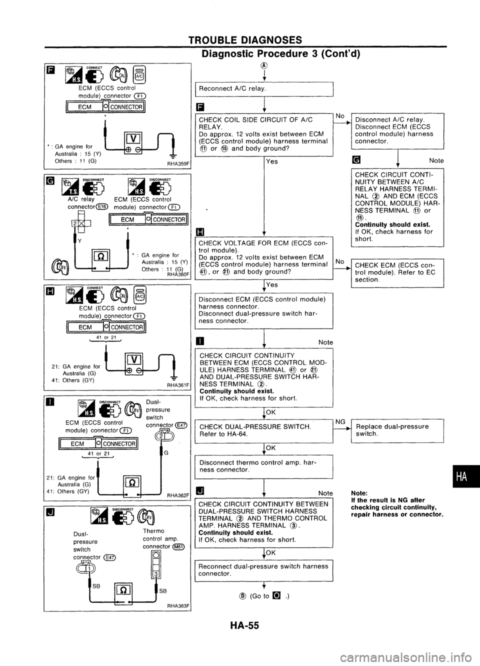
CHECK DUAL-PRESSURE SWITCH.
Refer toHA-64.
Disconnect thermocontrolamp.har-
ness connector.
CHECK
CIRCUIT CONTINUITY
BETWEEN ECM(ECCS CONTROL MOD.
ULE) HARNESS TERMINAL
@
or
@
AND DUAL-PRESSURE SWITCHHAR-
NESS TERMINAL @.
Continuity shouldexist.
If OK, check harness forshort.
OK
@ (Go to
m .)
Disconnect
ECM(ECCS contraImodule)
harness connector.
Disconnect dual-pressure switchhar-
ness connector.
CHECK CIRCUIT CONTINUITY BETWEEN
DUAL.PRESSURE SWITCHHARNESS
TERMINAL @AND THERMO CONTROL
AMP. HARNESS TERMINAL
@.
Continuity shouldexist.
If OK, check harness forshort.
Reconnect dual-pressure switchharness
connector.
o
CHECK
COILSIDECIRCUIT OFAIC No
Disconnect A/Crelay.
~
RELAY. Disconnect
ECM(ECCS
Do approx. 12volts exist between ECM control
module) harness
(ECCS control module) harnessterminal connector.
@
or@ and body ground?
l
Yes
~Note
CHECK CIRCUIT CONTI-
NUITY BETWEEN AIC
RELAY HARNESS TERMI-
NAL @AND ECM (ECCS
CONTROL MODULE)HAR-
.
NESSTERMINAL
@
or
@.
Continuity shouldexist.
(I) If
OK, check harness for
CHECK VOLTAGE FORECM (ECCS con- short.
tral module) .
Do approx. 12volts exist between ECM
NoCHECK ECM(ECCS con-
(ECCS
control module) harnessterminal
-..
@, or@ and body ground?
trolmodule). RefertoEC
section.
Yes
TROUBLE
DIAGNOSES
Diagnostic Procedure3(Conl'd)
@
~
I
Reconnect AICrelay. _
Ii
!
RHA359F
RHA362F
II
RHA361F
G
Dual-
pressure
switch
connector@
~.
S8
Thermo
control amp.
OOD
tm
@
•
:GA engine for
Australia :15 (Y)
Others :11 (G)
RHA360F
S8
Dual-
pressure
switch
connector
@
d))
~15@a
EGM (EGGS control
module) connec1or@
EGM
E[CONNECTORII
41 or21
.
II
•
:GA engine for
Australia: 15(Y)
Others :11 (G)
21: GAengine for
Australia (G)
41: Others (GY)
~&)
~Io
AlG relay EGM(EGGS control
connector@ module)connector@
ci
II
EGM
]g
CONNECTOR
II
Y
21: GAengine for
Australia (G)
41: Others (GY)
Ii
~i)@a~
EGM (EGGS control
module) connector @
II
EGM
]g
CONNECTOR
II
o
III
~i)
@a~
EGM (EGGS control
module) connector@
II
EGM 'gCONNECTORII
41 or21
.
RHA363F HA-55
Page 1458 of 1701
~CONNECT ~
(gl
l41E) ~
@
EGM (EGGS control
module) connector
@
II
EGM
J9"CONNECTORII
11 TROUBLE
DIAGNOSES
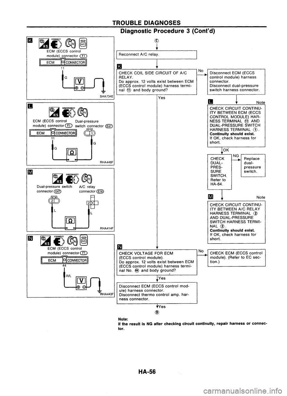
Diagnostic Procedure3
(Co nt'd)
~ ~
I
Reconnect AICrelay_. _..._
II
!
EGM (EGGS control Dual-pressure
module) connector
@
switch connector
@
II
ECM
Ej'coNNEcTORII ~
11
GSHA734E
Note
CHECK CIRCUIT CONTINU-
ITY BETWEEN ECM(ECCS
CONTROL MODULE)HAR-
NESS TERMINAL @AND
DUAL-PRESSURE SWITCH
HARNESS TERMINAL
CD.
Continuity shouldexist.
If OK, check harness for
short. Disconnect
ECM(ECCS
control module) harness
connector. Disconnect dual-pressure
switch harness connector.
II
CHECK
COILSIDECIRCUIT OFAIC
RELAY.
Do approx. 12volts exist between ECM
(ECCS control module) harnesstermi.
nal @and body ground?
Yes
G
II
G
Dual-pressure switch
connector@ RHA446F
NC relay
connector@ ~OK
CHECK
DUAL-
PRES-
SURE
SWITCH. Refer to
HA-64. NG
--+
Replace
dual-
pressure
switch.
Note
"='RHA443F
~i)~@
EGM (EGGS control
module) connector@
II
EGM
E[CONNECTORII
44
L
R/L
L
RHA414F
II
CHECK VOLTAGE FORECM
(ECCS control module).
Do approx. 12volts exist between ECM
(ECCS control module) harnesstermi-
nal No.
@
and body ground?
Yes
Disconnect ECM(ECCS control mod-
ule) harness connector.
Disconnect thermocontrol amp.har-
ness connector.
No
CHECK
CIRCUIT CONTINU-
ITY BETWEEN AICRELAY
HARNESS TERMINAL
@
AND DUAL-PRESSURE
SWITCH HARNESS TERMI-
NAL @.
Continuity shouldexist.
If OK, check harness for
short.
CHECK ECM(ECCS control
module). (RefertoEC sec-
tion.)
Yes
@
Note:
If the result isNG after checking circuilcontinuity, repairharness orconnec-
tor.
HA-56
Page 1461 of 1701
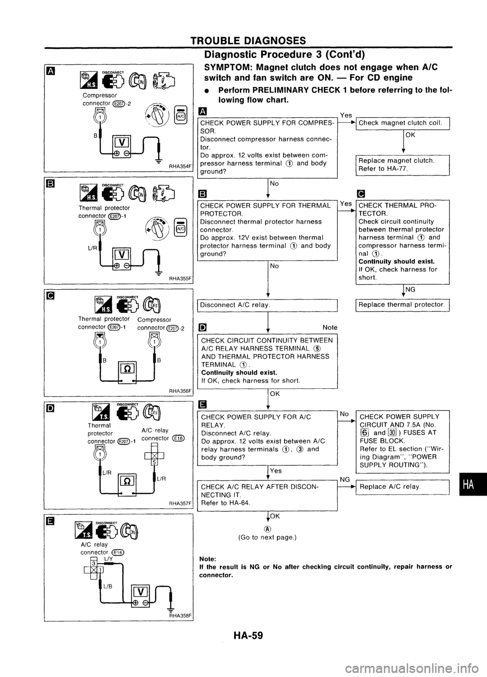
TROUBLEDIAGNOSES
Diagnostic Procedure3(Cont'd)
SYMPTOM: Magnetclutchdoesnotengage whenAle
switch andfanswitch areON. -For CDengine
• Perform PRELIMINARY CHECK1before referring tothe fol-
lowing flowchart.
Compressor
connector
@Q7>-2
~ B
Thermal protector
connector
@Q7>-1
~
LlR
RHA354F
RHA355F
m
CHECK POWER SUPPLY FORCOMPRES-
SOR. Disconnect compressor harnessconnec-
tor. Do approx. 12volts exist between com-
pressor harness terminal
CD
and body
ground?
No
(;J
CHECK POWER SUPPLY FORTHERMAL
PROTECTOR.
Disconnect thermalprotector harness
connector. Do approx. 12Vexist between thermal
protector harnessterminal
G)
and body
ground?
NoYes
Check magnet clutchcoil.
OK
Replace magnetclutch.
Refer toHA-77.
[!]
Yes CHECK THERMAL PRO-
TECTOR. Check circuitcontinuity
between thermalprotector
harness terminal
G)
and
compressor harnesstermi-
nal
CD.
Continuity shouldexist.
If OK. check harness for
short.
NG
Disconnect AICrelay.
I
Replace thermalprotector.
Thermal protector Compressor
connector@-1 connector@QD-2
j. ~~
1-
I1iJ
RHA356F Note
CHECK CIRCUIT CONTINUITY BETWEEN
AIC RELAY HARNESS TERMINAL
@)
AND THERMAL PROTECTOR HARNESS
TERMINAL G).
Continuity shouldexist.
If OK. check harness forshort.
OK
Thermal
protector AlCrelay
connector @:>-1connector
@])
~ ciP
~/R ~
1
~L1R
RHA357FCHECK
POWER SUPPLY FORAIC
RELAY.
Disconnect AICrelay.
Do approx. 12volts exist between AIC
relay harness terminals
CD.
@and
body ground?
Yes
CHECK AICRELAY AFTERDISCON-
NECTING IT.
Refer toHA-64. No
NG CHECK
POWER SUPPLY
CIRCUIT AND7.5A(No.
~J
and
00)
FUSES AT
FUSE BLOCK.
Refer toEL section ("Wir-
ing Diagram", "POWER
SUPPLY ROUTING").
Replace AICrelay.
•
RHA358F OK
@
(Go tonext page.)
Note:
If
the result isNG orNo after checking circuitcontinuity, repairharness or
connector.
HA-59
Page 1462 of 1701
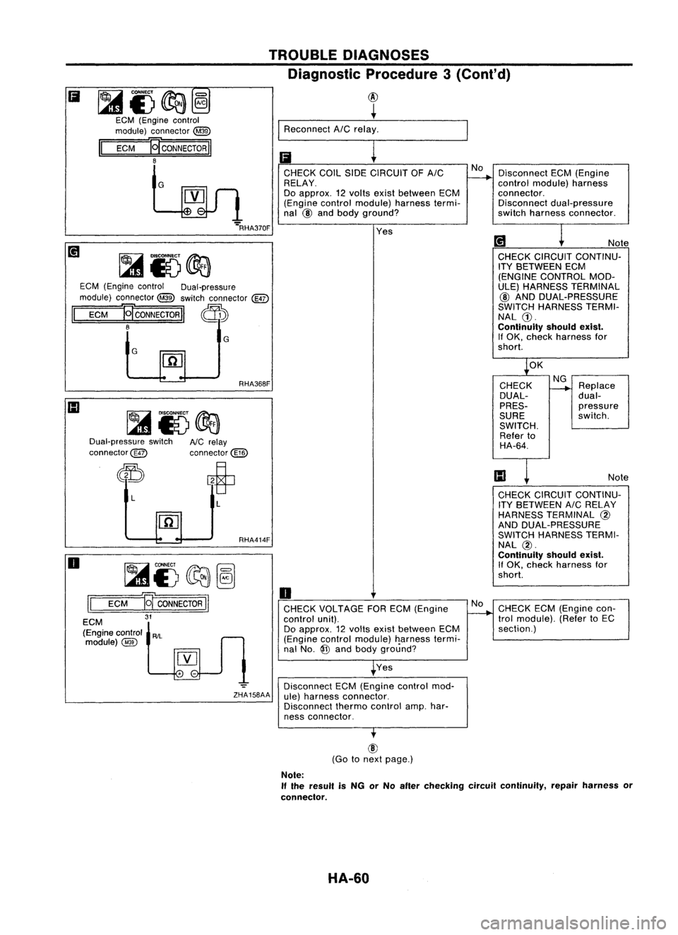
DisconnectECM(Engine
control module) harness
connector. Disconnect dual-pressure
switch harness connector .
Ii
~i)~@
ECM (Engine control
module) connector
@
II
ECM
E[CONNECTORII
8
G TROUBLE
DIAGNOSES
Diagnostic Procedure3(Cont'd)
@
+
I
Reconnect AICrelay.
Ii
r---
CHECK COILSIDECIRCUIT OFAIC No
RELAY.
Do approx. 12Yolts existbetween ECM
(Engine controlmodule) harnesstermi-
nal
@
and body ground?
G
G
ECM
(Engine control Dual-pressure
module) connector ~switch connector
@)
II
ECM
HCONNECTORII ~
8
[iJ
Note
CHECK CIRCUIT CONTINU-
ITY BETWEEN ECM
(ENGINE CONTROL MOD-
ULE) HARNESS TERMINAL
@ AND DUAL-PRESSURE
SWITCH HARNESS TERMI-
NAL G).
Continuity shouldexist.
If OK, check harness for
short.
Yes
....
RHA370F
OK
Dual-pressure switch
connector@ RHA368F
AlC relay
connector@ CHECK
DUAL-
PRES-
SURE
SWITCH. Refer to
HA-64.
NG
Replace
dual-
pressure
switch.
Note
~i5~~
ECM
11
CONNECTOR
II
31
o
L
II
ECM
(Engine control
AIL
module)@ L
RHA414F
o
CHECK VOLTAGE FORECM (Engine
control unit).
Do approx. 12YOIts exist between ECM
(Engine controlmodule) Ilarnesstermi-
nal No.
@
and body ground?
Yes
-=
Disconnect ECM(Engine controlmod-
ZHA158AA ule)harness connector.
Disconnect thermocontrolamp.har-
ness connector. No
CHECK
CIRCUIT CONTINU-
ITY BETWEEN AICRELAY
HARNESS TERMINAL
@
AND DUAL-PRESSURE
SWITCH HARNESS TERMI-
NAL
@.
Continuity shouldexist.
If OK, check harness for
short.
CHECK ECM(Engine con-
trol module). (RefertoEC
section.)
@
(Go tonext page.)
Note:
If the result isNG orNo after checking circuitcontinuity, repairharness or
connector.
HA-60
Page 1466 of 1701
TROUBLEDIAGNOSES
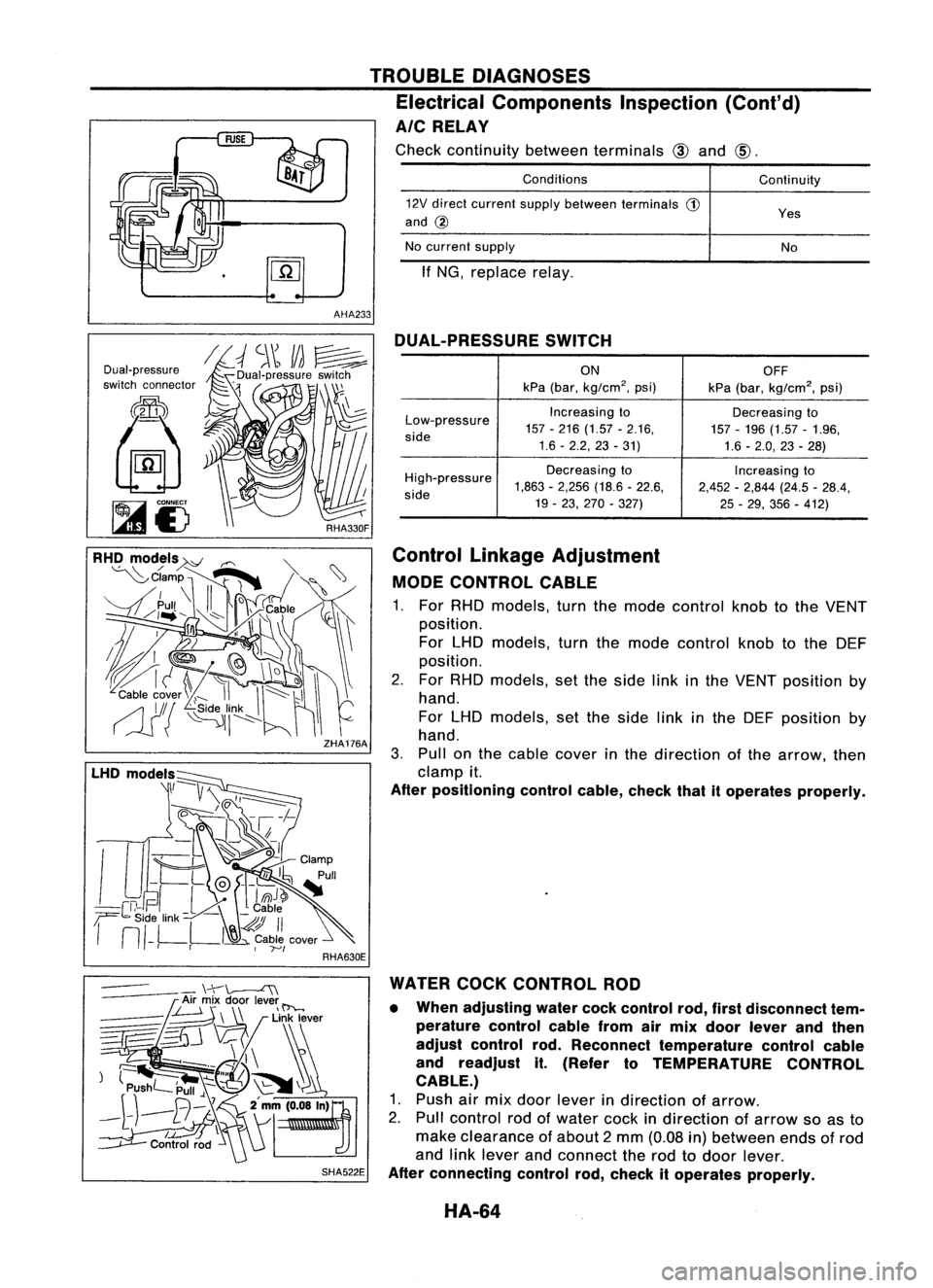
Electrical Components Inspection(Cont'd)
AIC RELAY
Check continuity betweenterminals
CID.
AHA233
Conditions
12V direct current supplybetween terminals
G)
and
@
No current supply
If NG, replace relay. Continuity
YesNo
Dual-pressure
switch connector
SHA522EDUAL-PRESSURE
SWITCH
ON OFF
kPa (bar,
kg/cm
2,
psi)
kPa(bar,
kg/cm
2,
psi)
Low-pressure Increasing
to
Decreasingto
157 -216 (1.57 -2.16,
157-196 (1.57-1.96,
side
1.6-2.2,23 -31)
1.6-2.0,23 -28)
High-pressure Decreasing
to
Increasingto
1,863 -2,256 (18.6-22.6,
2,452-2,844 (24.5-28.4,
side
19-23, 270 -327)
25-29, 356 -412)
Control Linkage Adjustment
MODE CONTROL CABLE
1. For RHO models, turnthemode control knobtothe VENT
position.
For LHO models, turnthemode control knobtothe OEF
position.
2. For RHO models, setthe side linkinthe VENT position by
hand.
For LHO models, setthe side linkinthe OEF position by
hand.
3. Pullan thecable cover inthe direction ofthe arrow, then
clamp it.
After positioning controlcable,checkthatitoperates properly.
WATER COCKCONTROL ROD
• When adjusting watercockcontrol rod,firstdisconnect tem-
perature controlcablefromairmix door lever andthen
adjust control rod.Reconnect temperature controlcable
and readjust it.(Refer toTEMPERATURE CONTROL
CABLE.)
1. Push airmix door lever indirection ofarrow.
2. Pull control rodofwater cockindirection ofarrow soasto
make clearance ofabout 2mm (0.08 in)between endsofrod
and linklever andconnect therod todoor lever.
After connecting controlrod,check itoperates properly.
HA-64
Page 1634 of 1701
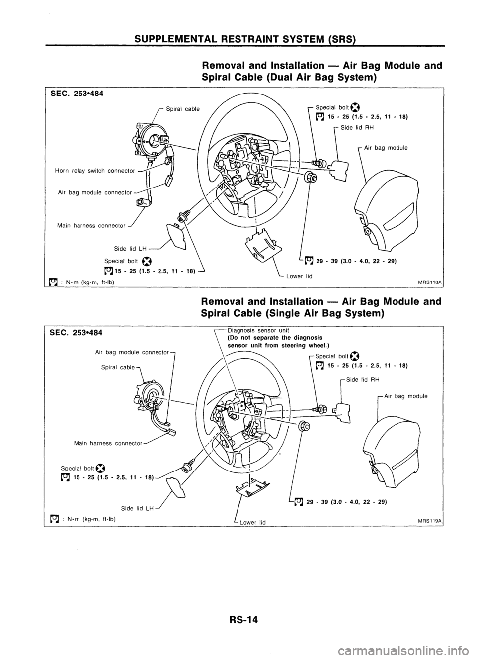
SUPPLEMENTALRESTRAINTSYSTEM(SRS)
Removal andInstallation -Air Bag Module and
Spiral Cable(DualAirBag System)
SEC. 253-484
Horn relayswitch connector
Special bolt~
to:J
15-25 (1.5 -2.5,
11-
18)
to:J :
N.m (kg-m. ft-Ib) Special
bolt~
to:J
15.25 (1.5•2.5,
11•
18)
Side lidRH
Air bag module
to:J
29-39 (3.0 -4.0, 22-29)
Lower lid
MRS118A
Removal andInstallation -Air Bag Module and
Spiral Cable(Single AirBag System)
SEC. 253-484
Airbag module connector
Spiral cable
A'
Special bolt~ ~
t"J
15•25 (1.5 •2.5, 11•18)- ~
Side lidLH/
"-J
to:J :
N. m (kg-m. ft-Ib) ~DiagnOSiS
sensorunit
(Do notseparate thediagnosis
sensor unitfrom steering wheel.)
Special boll~
to:J
15-25 (1.5 -2.5,
11-
18)
~~ r
S;d, lidRH
~ (]A;,b'9
mod",
MRS119A
RS-14