Page 1379 of 1701

HOWTOPERFORM EFFICIENT DIAGNOSIS FORANELECTRICAL INCIDENT
Circuit Inspection (Cont'd)
Voltage checkmethod
1. Remove theblown fuseanddisconnect allloads (i.e.SW1 open, relaydisconnected andsolenoid •
disconnected) poweredthroughthefuse.
2. Turn theignition keytothe ONorSTART position. Verifybattery voltage atthe B
+
side ofthe fuse
terminal (oneleadonthe B
+
terminal sideofthe fuse block andone lead onaknown goodground).
3. With SW1 open andtheDMM leads across bothfuseterminals, checkforvoltage.
voltage; shortisbetween fuseblock andSW1 (point A).
no voltage; shortisfurther downthecircuit thanSW1.
4. With SW1 closed, relayandsolenoid disconnected andtheDMM leadsacross bothfuseterminals,
check forvoltage.
voltage; shortisbetween SW1andtherelay (point B).
no voltage; shortisfurther downthecircuit thantherelay.
5. With SW1 closed, relaycontacts jumpedwithfused jumper wirecheck forvoltage.
voltage; shortisdown thecircuit ofthe relay orbetween therelay andthedisconnected sole-
noid (point C).
no voltage; retracestepsandcheck power tofuse block.
GROUND INSPECTION
Ground connections arevery important tothe proper operation ofelectrical andelectronic circuits.
Ground connections areoften exposed tomoisture, dirtand other corrosive elements. Thecorrosion
(rust) canbecome anunwanted resistance. Thisunwanted resistance canchange theway acircuit
works. Electronically controlledcircuitsarevery sensitive toproper grounding. Aloose orcorroded groundcan
drastically affectanelectronically controlledcircuit.Apoor orcorroded groundcaneasily affectthecir-
cuit. Even when theground connection looksclean, therecanbeathin film ofrust onthe surface.
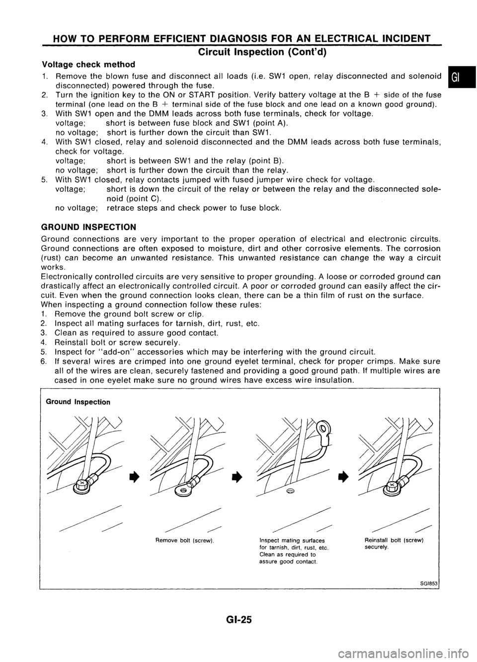
When inspecting aground connection followtheserules:
1. Remove theground boltscrew orclip.
2. Inspect allmating surfaces fortarnish, dirt,rust, etc.
3. Clean asrequired toassure goodcontact.
4. Reinstall boltorscrew securely.
5. Inspect for"add-on" accessories whichmaybeinterfering withtheground circuit.
6. Ifseveral wiresarecrimped intoone ground eyeletterminal, checkforproper crimps. Makesure
all ofthe wires areclean, securely fastened andproviding agood ground path.Ifmultiple wiresare
cased inone eyelet makesurenoground wireshaveexcess wireinsulation.
Ground Inspection
•
Removeboll(screw).
•
GI-25
Inspect
matingsurfaces
for tarnish. dirt.rust. etc.
Clean asrequired to
assure goodcontact.
•
Reinstallbolt(screw)
securely.
SGI853
Page 1383 of 1701

HOWTOFOLLOW FLOWCHART INTROUBLE DIAGNOSES
NOTICE
The flow chart indicates workprocedures requiredtodiagnose
problems effectively. Observethefollowing instructions before
diagnosing.
1) Use theflow chart afterlocating probable causesofaprob-
lem following the"Preliminary Check",the"Symptom
Chart" orthe "Work Flow".
2) After repairs, re-check thattheproblem hasbeen com-
pletely eliminated.
3) Refer toComponent PartsandHarness Connector Location
for the Systems described ineach section foridentificationl
location ofcomponents andharness connectors.
4) Refer tothe Circuit Diagram forQuick Pinpoint Check.
If you must check circuit continuity betweenharnesscon-
nectors inmore detail, suchaswhen asub-harness isused,
refer toWiring Diagram ineach individual sectionandHar-
ness Layout inEL section foridentification ofharness con-
nectors.
5) When checking circuitcontinuity, ignitionswitchshould be
"OFF" .
6) Before checking voltageatconnectors, checkbattery volt-
age.
7) After accomplishing theDiagnostic Procedures andElectri-
cal Components Inspection,makesurethatallharness con-
nectors arereconnected asthey were.
•
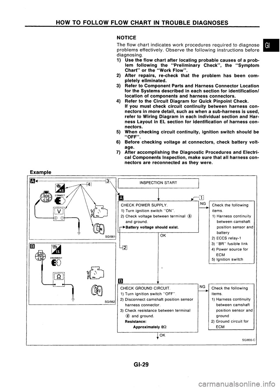
Example
m ..
-=-=~-----------~
~
~i5
[YJ
SGI561
~
OISCONNECT
18
SGI562
INSPECTION
START
CHECK POWER SUPPLY.
1) Turn ignition switch"ON".
2) Check voltage between terminal
@
and ground.
~Ba"ery voltageshouldexist.
OK
2
Ii)
CHECK GROUND CIRCUIT.
1) Turn ignition switch"OFF"
2) Disconnect camshaftpositionsensor
harness connector.
3) Check resistance betweenterminal
@
and ground.
Resistance: Approximately
on
OK
GI-29 NG
Check
thefollowing
items. 1) Harness continuity
between camshaft
position sensorand
battery
2) ECCS relay-1
3) "SR" fusible link
4) Power source for
ECM
5) Ignition switch
Check thefollowing
items. 1) Harness continuity
between camshaft
position sensorand
ground
2) Ground circuitfor
ECM
SG1800-C
Page 1436 of 1701
TROUBLEDIAGNOSES
Circuit Diagram -Air Conditioner
DUAL-PRESSURE
SWITCH
AIR
CONDITIONER
RELAY
THERMO
CONTROL
AMP.
IT
o
f-
U1
H
~
IT
W
I
f-
AIC
SWITCH
M
BLOWER
MOTOR
FAN
RESISTOR
GE
C
FAN SWITCH
OFF1234
GA
D
o
uo
HH
[LO
IZW
>w>
U..J....J
404
HUJ>
IT
o
..JI-
«u
~w
IT
I-
wo
IIT
f-(L
IT
o
U1
U1
W
IT
(L
~
o
u
RECIRCULA
nON
SWITCH
1
AIT models
MIT
models
For Europe andIsrael
Except
@
GA engine models
Except
f
or Europe, Israe 1and Austra 1ia
GA eng ine
f
or Europe, Israe1and Austra 1ia and SReng Ine
Except
@
LHD
AIT
models forEurope without daytIme lightsystem
Except
@
41.
@
44
@:
@:
@:
@:
@:
@:
@:
@:
:
@:
*1
To
illumination
system
HHA001
HA-34
Page 1437 of 1701
TROUBLEDIAGNOSES
Circuit Diagram -Air Conditioner (Cont'd)
I
I
I
I
I
I
I
I
I
I
I
I
I
I
I
I
I
I
I
I
I
I
I
I
I
I
I
I
I
---------,
M
COOLING COOLING
FAN FAN
MOTOR-l MOTOR-2
@ @
COOLING
FAN
RELAY-l
<{
-'
4541 *1119 10
ECM(ECCS
CONTROL
MODULE)
A
B
Z
LL
(!)[\J
ZI
HCI:
-10
01-
00
U::E
Z
LL
(!)
[\J
Z I
H
>-
-I
OZ-I
O
ULLCI:
(!)
~
Z I
H
>-
-I
OZ-I
O
ULLCI:
41119 10
ECM(ECCS
CONTROL
MODULE)
A
L ~
(SR20DE engine
AIT
models)
L
~
(GA engine except forAustralia
and SR20DE engine
MIT
models)
•
M
COOLING
FAN
RELAY-2
@
COOLING
FAN
MOTOR-2
@
COOLING
FAN
RELAY-l
COOLING COOLING
FAN FAN
MOTOR-l MOTOR-2
@
@
35 2115 13 14
ECMIECCS
CONTROL MODULE)
A
o
,
Z
I
LL
I
(!)(Tl
I
ZI
H>-
I
-I
,
0-1
ow
I
ucr
I
I
I
I
I
I
I
I
Z
I
I
LL
I
(!)(\J
I
ZI
I
HCI:
-10
I
OI-
I
00
U::E
I
I
I
I
I
I
I
I
I
I
I
Z
LL
(!)(\J
ZI
H>-
-I
0-1
ow
UCI:
Z
LL
(!) ....
ZI
H>-
-I
0-1
ow
UCI:
31 B9 10
ECM(ENGINE
CONTROL MODULE)
A
Z
LL
B
(!)~
ZI
HCI:
-10
01-
00
U::E
L
J
(C020 engIne) (GAI6DE
engIneforAustralIa)
HHA014
HA-35
Page 1442 of 1701
TROUBLEDIAGNOSES
Wiring Diagram -
A/C -
(Cont'd)
HA-A/C-03
Refer toEL-POWER.
....
L/R
-@>
ToHA-A/C-06
....
~Nextpage
*5
-4-
-(t>
Next page
*4
A!C
SWITCH
~
:
LHOmodels
RHOmodels
@:
GAengine
@:
GAengine forEurope. Israel
and Australia andSRengine
@:
Except@
*1"'(0 G/Y
LG/B
,
*4"'(0 G/B
GY
,
*5 ... @Y @L
,
I
.:., INDICATOR~
I
*1~
-4-
*1
-e>
ToHA-A/C-05
O~I-O-eb:>-
G/Yi8J~ JUNCTION
• BOXNo.2
0
1
~O~
G/Y
(j
(~g~~~CTORS)
_IIIIIIC~::. •G/Y
(j ~:(0
L/Y
Preceding~ LIB'
I
page ~
LIB
L/Y
IT ]1,rR
n
CONOITIONAER
U
RELAY
1bi=Jl1!:l=Jlm>
*5 L/R
I
I
Preceding~LG/R"""""'1
page ~
LG/R
u=tru
To HA-A/C-01 ~*1
LQl@
~ W
Refer
tolast page
(Foldout page).
~
HHA004
HA.40
Page 1446 of 1701
TROUBLEDIAGNOSES
Wiring Diagram -
A/C -
(Conl'd)
COOLING FANCONTROL
SR20DE engineMfTmodels, GAengine MfTmodels, GAengine AfTmodels -except for
Australia
HA-A/C-07
BATTERY (Via
fusible link)
30A
m
FUSE
RefertoEL-POWER.
BLOCK
(JIB)
<0:
LHOmode Is
@:
RHOmodels
@:
GA
engine for
Australia
@:
Except@
*17"@9 @14
•
I
EeN
(ECCS
CONTROL
MOOULE)
em
2
~
OotS)
O-eDoLG/RoI!jJoLG/Ri
~LG/R~ LGIR-eJD-O
~@
I
LG/R~
rn
........ @
LG/R
I,
LG/R
nilln
RFRL
GY
IQ~OI
I
BR
--I
I
GY SR
I
~I
'X(OCLING
n
FAN
U
RELAY-1
1bi=JJ1'=iJI
G/B
LG/R
I
I
T'---I
G/B G/B
~1 ~1
COOLING
COOLING
FAN FAN
M
MOTOR-1
M
MOTOR-2
rn m
IbiJl
IbjJJ
B B
1_--1
I
"
B
B
-:!:- -:!:-
mffi
+
2 1L
5
;Q..~~
~GY'GY
Refer
tolast page
(Foldout page).
(MS),
~
em
HHA006
HA-44
Page 1448 of 1701
TROUBLEDIAGNOSES
Wiring Diagram -
A/C -
(Cont'd)
GA engine AfTmodels -for Europe LHDwithout daytime lightsystem (withdealer installed
towing kit)
HA-A/C-09
BATTERY (Via
fusible link)
t
COOLING
FAN
MOTOR-2
~
•
I
GIS
G/Y
ID
$-$@g)
GIS
G/Y
mrn
La Hi
1+) 1+)
-
COOLING
FAN
MOTOR-1
Hi La~ HiLa
H H~ HH
IkjJJ ~ ~~
LG/S S
@D
LG/SS~
IrjJ~ -
$
66
IrjJ~-
i$/
6
LG/S S
@
LG/SS
ID
I-I
&-_I!__~.,
S S
~ ~
~~
SR
GYLG/S
~ ~RELAY-2
~~~rn> LG
G/Y
S
I '
-
.
i
I
T-
GIS G/Y@
IciJ~ -
t~J1@D
GIS G/Y
mm
La Hi
1+) (+)
Refer
toEL-POWER.
I
ECM
(ECCS
CONTROL
MODULE)
em
FUSE
BLOCK 30A
(JIB)
r-e-t
(El06) ~
IQ;OI
GY
BR _
1_
f-p:=_e:::::-
BR GY
1:Jt1 :lJIICOOLING
n
FAN
U
RELAY-1
IbjJJ
ILi=U
LG/R G/B
I
LG/R~ LG
~\EJQ!I ~
~M8----------~
Li~
I
LG/R~ LG
Iqp~-~~---------~qpl
LG/R
CEID
LG
m
ffiJl
2
RFRL RFRL
¥
@
2 1L
5
rffi\
@ID,
@?),
(f303), ~
t:]JY
GYGYGY GY
"2
57
@
36 SR
Refer
tolast page
(Foldout page).
CHID,
(El06)
em
@
W
HHA047
HA-46
Page 1449 of 1701
TROUBLEDIAGNOSES
Wiring Diagram -
Ale -
(Cont'd)
SR20DE engineAITmodels
HA-A/C-10
IGNITION SWITCH
ON orSTART
•
t
t
Refer tolast page
(Foldout page).
CHID
(El01)
,
(lliID
(IT)
t
t
-
COOLING
FAN
MOTOR-2
~
I
I
BR G/WLG/R
CDDLINGI:i:1 :lJ1
I~II
FAN
nn
RELAY-3
UU
~ I!:i=!IIl:i=lI
n,;JJ
LG
G/OR
B
1--&
Refer
toEL-POWER.
Hi
(-)
lLjJJ
LG/R B
___ I-_!,
rl.
B B
-!- -!-
~
~ m,(ffi)
\MJ GYGY
ECM
(ECCS
CONTROL
MODULE)
(ED
10A
FUSE
~.j;l
125
I
~J9~~
30A30A
(El06)
IT]
[B]
GY
G/W
I I
----,-I-F.~=
BRGY
G/W
BRGYLG/B
COOlING(!IIZ
I~II
CODLING11!1 ]II~II
~~~AY-1 .~ ~~~~AY-2 ~~
m> ~
Il:i=lI
4=Jl
@
I!:i=!IIl:i=lI
4=ll
LG/R
G/BG/R
LG
G/Y
B
r:r -
~r=!-JI
1-
I$~ --- ~$I
G/B G/R
LG
CHID
LG/R
m m
I I
[+)
COOLING
[+)
FAN
LG ~LG/R MOTOR-1
1c!J~
-F~:
~c!J1
Lo
rn
LG
CEID
LG/R
I
J
I
f
LG LG/R
~ m
RFRH RFRL
~ m>,,(E18)
IIDm
BRBRBR
HHA010
HA-47