Page 1072 of 1701
SEF511PA
•
No
Yes
Continuity
Conditions
12V direct current supplybetween
terminals
CD
and
@
No current supply
If NG, replace relay.
=
TROUBLE
DIAGNOSIS FORNON-DETECTABLE ITEMS
Cooling FanControl (Cont'd)
COMPONENT INSPECTION
Cooling fanrelay (M/Tmodels)
Check continuity betweenterminals
@
and
CID.
MIT
models
Coolingfanrelays-1, -2and -3(A/T models)
Check continuity betweenterminals
@
and
CID,
@and
(j).
AlT
models
Conditions
12V direct current supplybetween
terminals
CD
and
@
No current supply
If NG, replace relay.
Continuity
YesNo
SEC202BA
Terminals
Speed
(Ee)
(8)
Low
CD
@
(A/T
models)
Cooling fan High
CD,@
@,@
motor
(A/T
models)
High
CD@
(M/T models)
Cooling fanmotor should operate.
If NG, replace coolingfanmotor.
Cooling
fanmotors-1 and-2
1. Disconnect coolingfanmotor harness connectors.
2. Supply cooling fanmotor terminals withbattery voltage and
check operation.
AEC715
Cooling
fanmotor
harness connector
For MIT models
For
AIT Models
AEC,81EC-353
Page 1102 of 1701
relay-2ENGINE
ANDEMISSION CONTROLOVERALLSYSTEM
Component PartsLocation
Engine coolant
temperature sensor
Glowplugs
•
EC-383 SEF159R
Page 1105 of 1701
ENGINEANDEMISSION CONTROL OVERALLSYSTEM
System Chart
Ignition key
Engine coolant temperature
sensor Quick-glow
system
Partial loadadvance (PLA)
control Glow
relay
&
glow lamp
Solenoid timer
Engine speedsensor
Air conditioner switch
Battery voltage
Vehicle speedsensor
ECM
(Engine
control module) Coolingfancontrol
Air conditioner cutcontrol
EC-386
Cooling
fanrelay
Air conditioner relays
Page 1107 of 1701

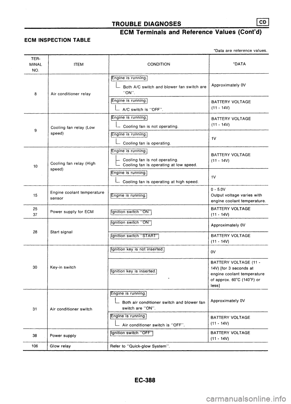
ECMINSPECTION TABLE TROUBLE
DIAGNOSES ~
ECM Terminals andReference Values(Coni'd)
-Data arereference values.
TER-
MINAL ITEM CONDITION -DATA
NO.
IEngineisrunning.1
L Both
AIC
switch andblower fanswitch areApproximately
OV
8 Air
conditioner relay "ON".
IEngine isrunning.1
BATTERYVOLTAGE
LAIC switchis"OFF". (11
-14V)
IEngine isrunning.1
BATTERY VOLTAGE
Cooling fanrelay (Low L
Cooling fanisnot operating. (11-14V)
9
speed) IEngineisrunning
I
L
Cooling fanisoperating. 1V
IEngine isrunning.1
BATTERYVOLTAGE
Cooling fanrelay (High
t
Cooling fanisnot operating.
(11-14V)
10 Cooling
fanisoperating atlow speed.
speed) IEngineisrunning.1
L
Cooling fanisoperating athigh speed. 1V
0- 5.0V
15 Engine
coolant temperature
IEngineisrunning.1 Output
voltage varieswith
sensor enginecoolant temperature.
25 jlgnitionswitch"ON"I BATTERY
VOLTAGE
37 Power
supply forECM
(11-14V)
jlgnition switch"ON"I
ApproximatelyOV
28 Startsignal
llgnitionswitch"START"I SA
TTERY VOLTAGE
(11 -14V)
Ilgnition keyisnot inserted.1
OV
BATTERY VOLTAGE (11-
30 Key-in
switch
14V)[for3seconds at
Ilgnition keyisinserted.1
enginecoolant temperature
-
ofapprox. 60°C(140°F) or
less)
IEngine isrunning.1
L
Both airconditioner switchandblower fanApproximately
OV
31 Airconditioner switch switch
are"ON".
IEngine isrunning.1
BATTERYVOLTAGE
L
Airconditioner switchis"OFF". (11
-14V)
38 Power
supply Ilgnition
switch"OFF"I BATTERY
VOLTAGE
(11 -14V)
106 Glowrelay
Referto"Quick-glow System".
EC-388
Page 1109 of 1701

TROUBLEDIAGNOSES
Quick-glow System
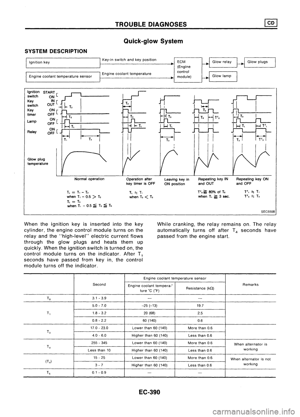
SYSTEM DESCRIPTION
Ignition key
Engine coolant temperature sensorKey-in
switch andkeyposition
Engine coolant temperature
ECM
(Engine
control
module) Glow
relay
Glow lamp Glow
plugs
Ignition START[~
~
switch
~~[ I
11
I
1iI
Key
~
switch OUT
-II-
T,
I
!
I
I-l
Key ONe
n
Hn
JTl-
.1"l....!:.1L-
~
timer
OFF
Ir1
To
I
UL
HTo
HT'o
Lamp ON
[
..Lfl
o~~
I
I-.J
TL
I
~
I
I-l
TL
I
I
I
I
I
HTL
I-l
T'L
Relay OFF
[j
I_
L-
r--L
.f"l.-.JL
~
T.
"'
II
I
II
~
1r;,1
I II I
I,
Glow plug
temperature
Normaloperation
Operationafter
key timer isOFF Leaving
keyin
ON position Repeating
keyIN
and OUT Repeating
keyON
and OFF
TL
=
T,-T,
when T,-0.5 >T,
TL
= T,
when T,-0.5 ~T,
;a;
To
TL
=.
T,
when To
<
T, T'o
~80% ofTo
when T.
5':
3sec.
T',
=.
T,
T',
=.
T,
SEC550B
When theignition keyisinserted intothekey
cylinder, theengine control module turnsonthe
relay andthe"high-level" electriccurrentflows
through theglow plugs andheats themup
quickly. Whentheignition switchisturned on,the
control module turnsonthe indicator. AfterT
1
seconds havepassed fromkeyin,the control
module turnsoffthe indicator. While
cranking, therelay remains on.The relay
automatically turnsoffafter T
4
seconds have
passed fromtheengine start.
Engine coolant temperature sensor
Second Enginecoolant tempera-' Remarks
ture 'C('F) Resistance
(kQ)
To
3.1
-3.9
- -
5.0 -7.0 -25(-13)
19.7
T,
1.8
-3.2
20(68)
2.5
0.8 -2.2 60(140)
0.6
17.0 -23.0
Lowerthan
60(140)
Morethan
0.6
T
3
40-6.0
Higherthan
60(140)
Lessthan
0.6
255 -345
Lowerthan
60(140)
Morethan
0.6
Whenalternator is
T
4
working
Less than
10
Higherthan
60(140)
Lessthan
0.6
15 -25
Lowerthan
60(140)
Morethan
0.6
Whenalternator isnot
(T
4)
working
3 -7
Higherthan
60(140)
Lessthan
0.6
T
5
0.1-0.9
- -
EC-390
Page 1113 of 1701
![NISSAN ALMERA N15 1995 Service Manual TROUBLEDIAGNOSES
Quick-glow System(Cont'd)
~
ill]
SEF941P
Ii]
~i5
Glow
Eill~
plug
0
@]Q]
2
[ill
~SEF942P INSPECTION
START
Check fuellevel, fuelsupplying system,
~Correct.
starter motor NISSAN ALMERA N15 1995 Service Manual TROUBLEDIAGNOSES
Quick-glow System(Cont'd)
~
ill]
SEF941P
Ii]
~i5
Glow
Eill~
plug
0
@]Q]
2
[ill
~SEF942P INSPECTION
START
Check fuellevel, fuelsupplying system,
~Correct.
starter motor](/manual-img/5/57349/w960_57349-1112.png)
TROUBLEDIAGNOSES
Quick-glow System(Cont'd)
~
ill]
SEF941P
Ii]
~i5
Glow
Eill~
plug
0
@]Q]
2
[ill
~SEF942P INSPECTION
START
Check fuellevel, fuelsupplying system,
~Correct.
starter motor,etc.
OK
m
Check thatallglow plugconnecting
~Installproperly.
plate nutsareinstalled properly.
OK
CHECK OVERALL FUNCTION. OK
CHECK COMPONENT
Check entirequick-glow system.(Refer
---..
(Glowplug).
to "System Operation Check"onnext See
page EC-397.
page.)
NG
CHECK POWER SUPPLY ANDGROUND NG
Repair harness orcon-
CIRCUIT.
---..
nector.
(Refer to"Power Supplyandground
circuit forECM", EC-396).
OK
(!]
CHECK VOLTAGE BETWEEN GLOW NG
Check thefollowing.
RELA YAND GROUND.
---..
•7.5A fuse
1) Check voltage between terminals •
75A fusible link
G), @and ground withtester. •Harness continuity
Voltage: Batteryvoltage between
glowrelay
OK and
fuse
If NG, repair harness or
connectors.
[!1
CHECK OUTPUT SIGNALCIRCUIT. NG
Repair harness orcon-
1) Check harness continuity between
---+
nectors.
ECM terminal
@
andterminal @.
Continuity shouldexist.
OK
Ii]
CHECK HARNESS CONTINUITY NG
Repair harness orcon-
BETWEEN GLOWRELAY ANDGLOW
---+
nectors.
PLUG. 1) Disconnect ECMharness connector.
2) Disconnect glowrelay.
3) Check harness continuity between
glow relay terminal
@
and glow
plug.
Continuity shouldexist.
~OK
SEF940P
SEF939P
-"-.....
'y;-----...
Connecting platenut:J
~1.0 •1.5
N.mr-
"(0.1 •0.15 kg-m,- ""'-
8.7 -13.0 in-Ib)
~
""
.
'------
~
~
ECM
E1
CONNECTOR
II
106
II
(!]
~io
EC-394
Page 1114 of 1701

TROUBLEDIAGNOSES
Quick-glow System(Cont'd)
@
CHECK COMPONENTS NG
(Glow relay, Glowplug,Engine coolant
temperature sensor,Key-inswitch, Igni-
tion switch).
Refer to"Component Inspection"(EC-
397).
OK
Disconnect andreconnect harnesscon-
nectors inthe circuit. Thenretest.
Trouble isnot fixed.
Check ECMpinterminals fordamage or
the connection ofECM harness connec-
tor. Reconnect ECMharness connector
and retest. Replace
malfunctioning
component(s).
•
BATIERY [
Voltage
OV
Ignition
key
START
[
ON
IN [
OUT
,
,
,
I
,
JL
SEC5558SYSTEM
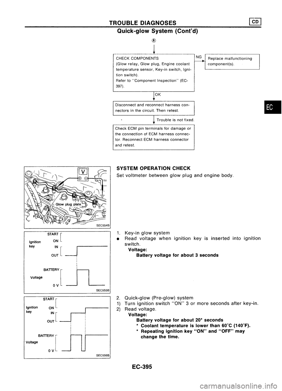
OPERATION CHECK
Set voltmeter betweenglowplugandengine body.
1. Key-in glowsystem
• Read voltage whenignition keyisinserted intoignition
switch.
Voltage: Battery voltage forabout 3seconds
Ignition
key
BATIERY [
Voltage
OV
SEC5568
2.
Quick-glow (Pre-glow)system
1) Turn ignition switch"ON"3or more seconds afterkey-in.
2) Read voltage.
Voltage: Battery voltage forabout 20*seconds
*
Coolant temperature islower than60°C(140°F).
* Repeating ignitionkey"ON" and"OFF" may
change thetime.
EC-395
Page 1116 of 1701
TROUBLEDIAGNOSES ~
Quick-glow System(Cont'd)
• If
NG.
check component partsandtheir related harness
according tothe following chart.
Parts which should bechecked
Terminal Fuse Glowin-
No. Battery IFusible Glow
Key-in Ignition
dicatorHarness
link relay
switch switch
bulb
@
XX
X
@
X
X X X
@
XX
X X
@,@
XX XX
@
XX X
X X
@
X
X XX
COMPONENT INSPECTION
Glow relay
1. Check relayforcoil continuity.
Continuity shouldexist.
2. Check relayforproper operation.
Coil voltage Continuity
Contactpoint
OV
NoOFF
12V
Yes ON
•
Ohmmeter SEC5648
SEF630K Glow
plug
1. Remove glowplugconnecting plate.
2. Check eachglow plugforcontinuity.
Continuity shouldexist:
Approximately 0.650
• IfNG, replace glowplug.
EC-397