1995 NISSAN ALMERA N15 relay
[x] Cancel search: relayPage 927 of 1701
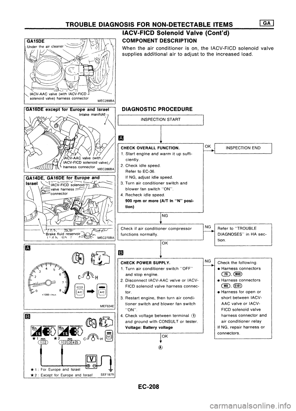
Referto"TROUBLE
DIAGNOSES" inHA sec-
tion.
Check thefollowing.
• Harness connectors
QD,@
• Harness connectors
@,@
• Harness foropen or
short between IACV-
AAC valve orIACV-
FICO solenoid valve
harness connector and
air conditioner relay
If NG, repair harness or
connectors.
O~L.-
__I_N_S_P_E_CT_I_O_N_E_N_D __
NG
NG
NG
INSPECTION
START
DIAGNOSTIC
PROCEDURE
Check ifair conditioner compressor
functions normally.
OK
OK
CHECK
POWER SUPPLY.
1. Turn airconditioner switch"OFF"
and stop engine.
2. Disconnect IACV-AACvalveorIACV-
FICO solenoid valveharness connec-
tor.
3. Restart engine, thenturnaircondi-
tioner switch andblower fanswitch
"ON".
4. Check voltage between terminal
(1)
and ground withCONSULTor tester.
Voltage: Batteryvoltage
SEF187R
MEC289BA
MEF634E
TROUBLE
DIAGNOSIS FORNON-DETECTABLE ITEMS
IACV-FICD SolenoidValve(Cont'd)
COMPONENT DESCRIPTION
When theairconditioner ison, the IACV-FICD solenoidvalve
supplies additional airtoadjust tothe increased load.
~n
* 1: For Europe andIsrael ~
t
* 2: Except forEurope andIsrael
GA14DE,
GA16DEforEurope an
Israel
~'IACV_FIICI~'~O~~'d~
(\ ~valve harness~
~ connector
/
GA
6DE except forEurope andIsrael
'""k,
mM,o"l \
~m
[' ~.CHECKOVERALL FUNCTION.
1. Start engine andwarm itup suffi-
{ iAcv-AAC valve(with / ciently.
IACV-FICD solenoidvalve)
harness connector MEC286BA 2.Check idlespeed.
Refer toEC-36.
If NG, adjust idlespeed.
3. Turn airconditioner switchand
blower fanswitch "ON".
4. Recheck idlespeed.
900 rpm ormore (AITin
"N"
posi-
tion)
EC-208
Page 945 of 1701
![NISSAN ALMERA N15 1995 Service Manual ENGINEANDEMISSION CONTROL OVERALLSYSTEM
Circuit Diagram
'"I"
~
COOLING
(!)~
U U
F~LAY-1
Z
I
f- f- H
0:
H H -'0
3:f- 3: OZf-
(f]0: (f]
--ttt
0<t0
<t ZZ UIL::E
ZI-
O(f] SO
~
H
NISSAN ALMERA N15 1995 Service Manual ENGINEANDEMISSION CONTROL OVERALLSYSTEM
Circuit Diagram
'"I"
~
COOLING
(!)~
U U
F~LAY-1
Z
I
f- f- H
0:
H H -'0
3:f- 3: OZf-
(f]0: (f]
--ttt
0<t0
<t ZZ UIL::E
ZI-
O(f] SO
~
H](/manual-img/5/57349/w960_57349-944.png)
ENGINEANDEMISSION CONTROL OVERALLSYSTEM
Circuit Diagram
'"I"
~
COOLING
(!)~
U U
F~LAY-1
Z
I
f- f- H
0:
H H -'0
3:f- 3: OZf-
(f]0: (f]
--ttt
0
O(f] SO
~
H
I-L f-
COOLING
HO H
Z Z
FAN
RELAY-2
r
(!) ru
(!)Z
(!)
r=-1
HO H
r-
~
REf"
I
Z
I
H 0:
~[j~ ~~
0
COOLING
-'
0
oz~@
FAN RELAY-3
8i1~
«
r=-1
rf=~I'
~
=
C;::A
,I'
0:
~
H
f-
H>-
O
O:Z-'
HOW
.c
L
u
0
'"
"'
0:
.M
"'
~
'"
0
"'
L
od
~r
U
a
E
::EO:
H
"-
0
~
O:f-' ::E
U
UJza.
II
T~
0
0
f-
f-
r
M A
(!)
-@---11'
Z
0: HW
W 0:0:
OD~~O
W:::>
W(f]
(!)
~
f-(f]
-tBt_
Z
I
(f]W
H 0: o:I
uw
-'
0
Lo:o.u
a:
@
CLc5
c---
OZf-
'"
W
f-
0
~"",
uu.::E
'"
OH3:
wo
'"
f-H
> OZO:
>-
E
0.0(f]
0:0 W-' WWO
-@---11'
0
f-(!)(f]
WZ 0
'-"-'
.c
"
>w
"'0:
WXW ZW
U
Z-' f-
IO(f) HO:
IU
00 WZ
--I
(!)ru
'"
~
U(f]
>0
-r-
OZ
Z
I
-'U o
0
WI
i
I
UIL
-'0 I-
::>UW >WW
OZI-@
cll-> "'>
0::::>--1 0:0:-'
I
I
8it~
«
O--l
!~
f-U>
wo.>
I
...
'!l
II)
~
eno
N
'"
:::
ru
S
-
...
r--
~
ECM(ECCS CONTROL MODULE)
,U
II
II
II
II
II
(1
--
0:
"'0
g~
zw
",(f]
II
~
o
z
a:
P-!I'
I
Z
-'0
f-Hf-
::>(/)o-<
W03: Zo.(/)
WZ
-'0
I-Ha:
I-f-O OH(f)
a:(/)Z
IOW
f-o.(/)
;;
~
II)
'"
Q)~J
:;:;
0
en~Q)
r--
ru
"IN- N
U
J
I
II
II
II
II
II
rn
i~
@
~",-I
~ij!
0::>
Uf-
zwo
Ho.(f)
"'::EZ
~~m
ij!
:::>
(f]
~
o.I
IU
-'f-
aD
c.-U
I
I
~
L-
a:
o
a:~
HW
'"
c
~
0
-u
"(!)
.....
'"
~
::>
.....
-u- I'~
D
C
'"
0
~
"'
"'
u
-u
"a:
rl
rl
'"
.~
~
0.
DD
-u
,,(/)
0
0
IU
E E
f- f-
.c
'"
"-
"-
i
..
..
..
@@@
o
o
H
o Z
W
-'
o
(/)
o
U
H
IL
IW
»
u-'
H>
j
i
I
I
I
(/)3
(f]0
~
-
I
I
I
I
f-Z
u.o
(/)H(f]
::E(/)Z
(
I
H
0:0:
f-O
(f)f-
H::>
om
0:
W
(f]
Z
W
51
o
~
.~
r--:l
l::':.J
~
f-
(f]
H
(/)
W
0:
-€
~I~~g
0:
~HU
o
f-
(f]
H
O:(f]
wz
~~-
0.1-
(T)
r--Q)(D
~tO~Ri
o~
...... ~8:::
(T)(T)
I 11
I
L
-
0:
0:0
HI--
>-
-.JQ.
W:E..J >:::J
~::lW
U(!)
~I~ ~I'
-'0.
W:;,:
::>::>
u.o.
I
U
I-
H
U5
is
H
I-
H
~
H
'"
BATTERY
-
(\J
ro
...
0
0
0
0
Z Z Z
Z
>-
0
III
II.I
~D
(f]
UW
wo:
.r=-1
0:
W
HQj-
0
>
f- --I
U
W >
-,
Z
U
H
>
U
'"
N
::';
(D
en
;:::
'"
~
!;:l
...
~ffi~
...
;:::
...
;:::
(T)
S
;:::
rLJ
I
I
0.
::E
Z-'
o
HO:
f-O
~~Q)
:::>u
ILH
-'0
I-
en
z
0
u
'"
~ (~~~ [j~~ ~
:s
-'
W
-'
m
~
~~
H
(f]
::>
u.
::J~'
~~ffi
Hf-Z
--IUO
wu
f-ZO:
HEC001
EC-226
Page 951 of 1701
ENGINEANDEMISSION CONTROLOVERALLSYSTEM
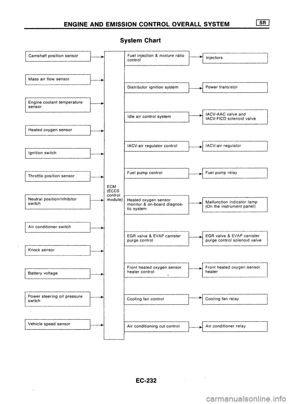
System Chart
Camshaft positionsensor Fuel
injection
&
mixture ratio
•
I
I
control Injectors
Mass airflow sensor
I
Distributorignitionsystem
r
~1
Power transistor
Engine coolant temperature
.
sensor
I
IACV-AAC valveand
Idle aircontrol system
IACV-FICDsolenoidvalve
Heated oxygen sensor
I
IACV-airregulator control
~--..j
IACV-air regulator
I
Ignition switch
I
I
Throttle position sensor
~-+
Fuel
pump control Fuel
pump relay
ECM
(ECCS
control
Neutral position/Inhibitor
.
module) Heatedoxygen sensor
switch monitor
&
on-board diagnos-
~-+
Malfunction
indicatorlamp
tic system (On
theinstrument panel)
I
Air conditioner switch
t~
EGRvalve
&
EVAP canister
1---+
EGR
valve
&
EVAP canister
purge control purge
control solenoid valve
Knock sensor
.....
Frontheated oxygen sensor Front
heated oxygen sensor
Battery voltage
.
heater
control heater
I
.
Power steering oilpressure
~
Coolingfancontrol
--
Cooling
fanrelay
switch
Vehicle speedsensor
.....
Airconditioning cutcontrol Air
conditioner relay
EC-232
Page 955 of 1701
A
N
600 1,000 1,4001,8002,200
Engine speed(rpm) SEF742M
Tp
(msec)
1.75
~ 1.50
.~
3l
1.25
:;
a.
c:
1.00
.Q
~ 0.75
E ENGINE
ANDEMISSION BASICCONTROL SYSTEMDESCRIPTION
Distributor Ignition(01)System (Cont'd)
SYSTEM DESCRIPTION
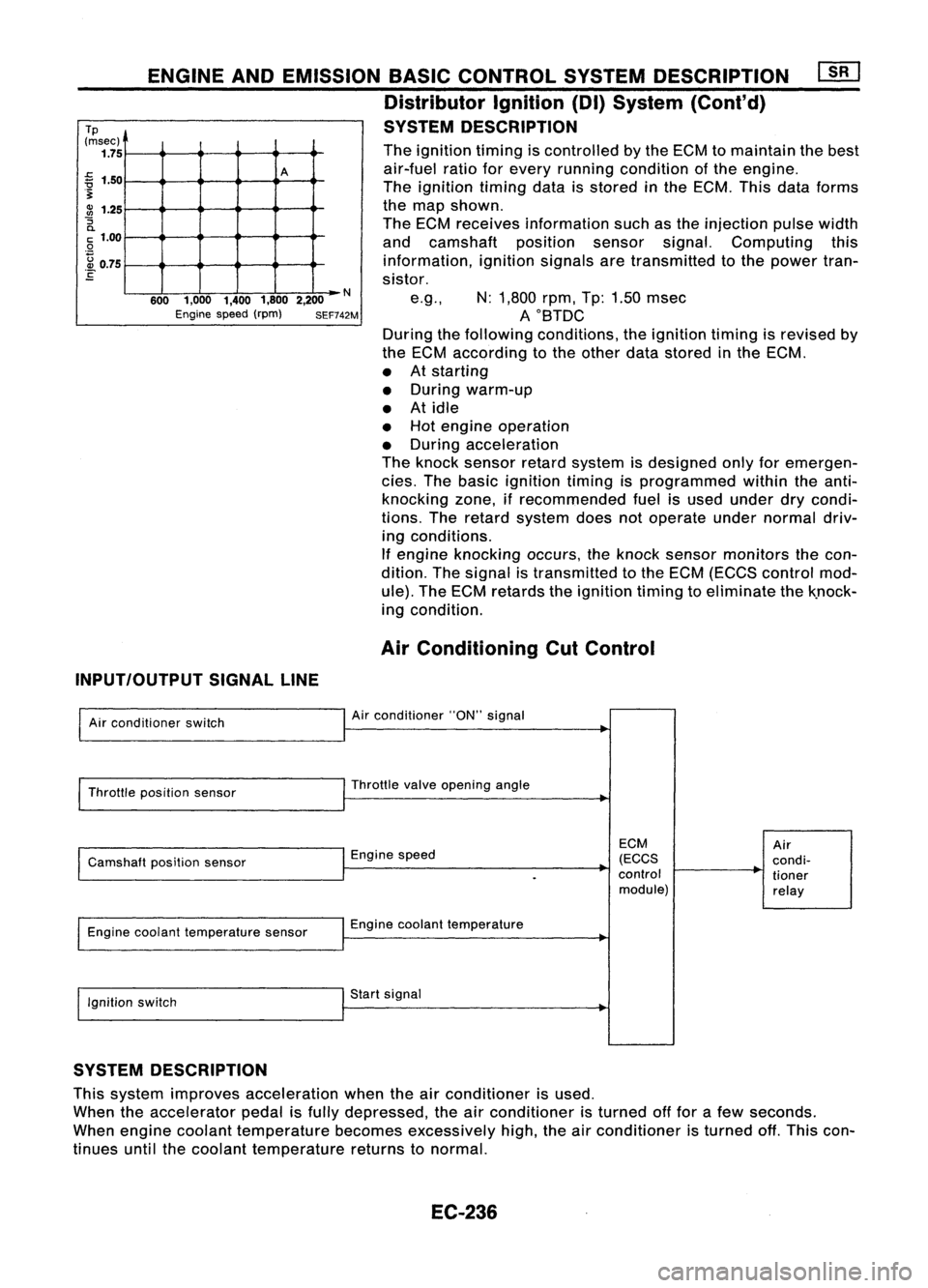
The ignition timingiscontrolled bythe ECM tomaintain thebest
air-fuel ratioforevery running condition ofthe engine.
The ignition timingdataisstored inthe ECM. Thisdataforms
the map shown.
The ECM receives information suchasthe injection pulsewidth
and camshaft positionsensorsignal.Computing this
information, ignitionsignalsaretransmitted tothe power tran-
sistor.
e.g., N:1,800 rpm,Tp:1.50 msec
AOBTDC
During thefollowing conditions, theignition timingisrevised by
the ECM according tothe other datastored inthe ECM.
• Atstarting
• During warm-up
• Atidle
• Hot engine operation
• During acceleration
The knock sensor retardsystem isdesigned onlyforemergen-
cies. Thebasic ignition timingisprogrammed withintheanti-
knocking zone,ifrecommended fuelisused under drycondi-
tions. Theretard system doesnotoperate undernormal driv-
ing conditions.
If engine knocking occurs,theknock sensor monitors thecon-
dition. Thesignal istransmitted tothe ECM (ECCS control mod-
ule). TheECM retards theignition timingtoeliminate thek.nock-
ing condition.
Air Conditioning CutControl
INPUT/OUTPUT SIGNALLINE
Air conditioner switch
Throttle position sensor
Camshaft positionsensor
Engine coolant temperature sensor
Ignition switch Air
conditioner "ON"signal
Throttle valveopening angle
Engine speed
Engine coolant temperature
Start signal
ECM
(ECCS
control module)
Air
condi-
tioner
relay
SYSTEM DESCRIPTION
This system improves acceleration whentheairconditioner isused.
When theaccelerator pedalisfully depressed, theairconditioner isturned offfor afew seconds.
When engine coolant temperature becomesexcessively high,theairconditioner isturned off.This con-
tinues untilthecoolant temperature returnstonormal.
EC-236
Page 974 of 1701
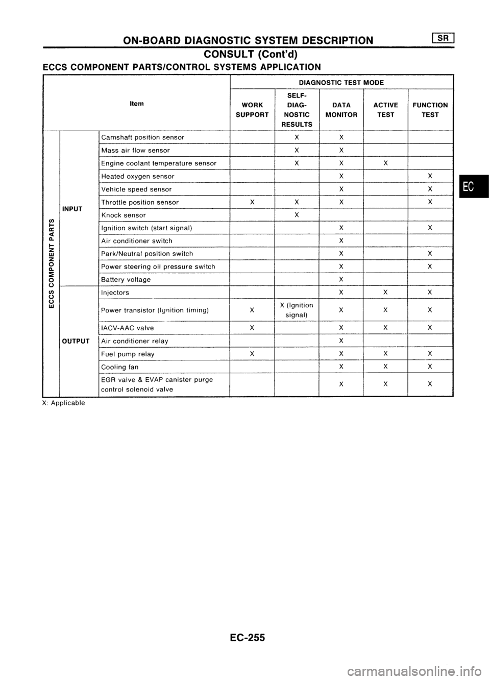
ON-BOARDDIAGNOSTIC SYSTEMDESCRIPTION
CONSULT (Coni'd)
ECCS COMPONENT PARTS/CONTROL SYSTEMSAPPLICATION
DIAGNOSTIC TESTMODE
SELF.
Item WORKDlAG.
DATAACTIVEFUNCTION
SUPPORT NOSTICMONITOR TESTTEST
RESULTS
Camshaft positionsensor XX
Mass airflow sensor XX
Engine coolant temperature sensor XX
X
Heated oxygen sensor X
X
Vehicle speedsensor X
X
Throttle positionsensor X
XX X
INPUT Knocksensor X
lJ)
~ Ignitionswitch(startsignal) X
X
a:
<
0-
Airconditioner switch X
~
z
Park/Neutralpositionswitch X
X
w
z
0
Powersteering oilpressure switch X
X
0-
:!
X
0
Battery
voltage
0
lJ)
Injectors XX
X
0
0
X(Ignition
w
Powertransistor (Iynitiontiming) X
XX
X
signal)
IACV-AAC valve XX
XX
OUTPUT Air
conditioner relay X
Fuel pump relay XXX
X
Cooling fan X
X
X
EGR valve
&
EVAP canister purge
X
X
X
control solenoid valve
X: Applicable
EC-255
•
Page 977 of 1701
![NISSAN ALMERA N15 1995 Service Manual ON-BOARDDIAGNOSTIC SYSTEMDESCRIPTION
CONSULT (Conl'd)
Monitored item ECM
Main
[Unit] input
signals Description
Remarks
signals
AIR COND SIG •Indicates [ON/OFF] conditionofthe
[ON/OFF]
00
air
NISSAN ALMERA N15 1995 Service Manual ON-BOARDDIAGNOSTIC SYSTEMDESCRIPTION
CONSULT (Conl'd)
Monitored item ECM
Main
[Unit] input
signals Description
Remarks
signals
AIR COND SIG •Indicates [ON/OFF] conditionofthe
[ON/OFF]
00
air](/manual-img/5/57349/w960_57349-976.png)
ON-BOARDDIAGNOSTIC SYSTEMDESCRIPTION
CONSULT (Conl'd)
Monitored item ECM
Main
[Unit] input
signals Description
Remarks
signals
AIR COND SIG •Indicates [ON/OFF] conditionofthe
[ON/OFF]
00
air
conditioner switchasdetermined
by the airconditioning signal.
PIN POSI SW
00
•
Indicates [ON/OFF] conditionfromthe
[ON/OFF] park/neutralpositionswitchsignal.
PW/ST SIGNAL •Indicates [ON/OFF] conditionofthe
[ON/OFF]
00
power
steering oilpressure switch
determined bythe power steering oil
pressure signal.
INJ PULSE [msec]
0
•
Indicates theactual fuelinjection •
When theengine isstopped, acertain
pulse widthcompensated byECM computedvalueisindicated.
according tothe input signals.
IGN TIMING [BTDC]
0
•
Indicates theignition timingcomputed
by ECM according tothe input sig-
nals.
IACV-AACIV
[%]
•Indicates theidle aircontrol valve
0
(AAC
valve) control valuecomputed
by ECM according tothe input sig-
nals.
A/F ALPHA [%J •Indicates themean valueofthe air- •When theengine isstopped, acertain
0
fuel
ratio feedback correction factor valueisindicated.
per cycle. •This dataalsoincludes thedata for
the air-fuel ratiolearning control.
AIR COND RLY •Indicates theairconditioner relay
[ON/OFF]
0
control
condition (determined byECM
according tothe input signal).
FUEL PUMP RLY •Indicates thefuel pump relaycontrol
[ON/OFFJ
0
condition
determined byECM accord-
ing tothe input signals.
COOLING FAN
•Indicates thecontrol condition ofthe
[HI/LOW/OFFJ coolingfans(determined byECM
0
according
tothe input signal).
HI ...High speed operation
LOW ...Low speed operation
OFF ...Stopped
EGRC SOLIV •Indicates thecontrol condition ofthe
[ON/OFFJ EGR
valve
&
EVAP canister Purge
control solenoid valve(determined by
0
ECM
according tothe input signal).
ON ...EGR andEVAP canister purge
operation cut-off
OFF ...EGR andEVAP canister purge
operation notcut-off
VOLTAGE •Voltage measured bythe voltage
[V] probe.
PULSE •Pulse width, frequency orduty cycle •Only "#"isdisplayed ifitem is
[msec] or[Hz] or
measuredbythe pulse probe. unabletobe measured.
[%]
•Figures with"#"s aretemporary
ones. Theyarethesame figures as
an actual pieceofdata which wasjust
previously measured.
EC-258
Page 978 of 1701

ON-BOARDDIAGNOSTIC SYSTEMDESCRIPTION
CONSULT (Conl'd)
ACTIVE TESTMODE
TEST ITEM CONDITION JUDGEMENTCHECKITEM(REMEDY)
• Engine: Returntothe original
•Harness andconnector
FUEL INJECTION trouble
condition
Iftrouble symptom disappears,
•Fuel injectors
• Change theamount offuel
seeCHECK ITEM.
•Heated oxygen sensor
injection usingCONSULT .
• Engine: Afterwarming up,idle
IACV-AACIV the
engine.
Enginespeedchanges according •Harness andconnector
OPENING •
Change theIACV-AAC valve
tothe opening percent. •
IACV-AAC valve
opening percentusingCON-
SULT.
• Engine: Returntothe original
•Harness andconnector
ENG COOLANT trouble
condition
Iftrouble symptom disappears, •
Engine coolant temperature
• Change theengine coolant
.
TEMP see
CHECK ITEM. sensor
temperature indicationusing
•Fuel injectors
CONSULT .
• Engine: Returntothe original
trouble condition
Iftrouble symptom disappears,
IGNITION TIMING•Timing light:Set •
Adjust initialignition timing
• Retard theignition timingusingsee
CHECK ITEM.
CONSULT.
• Engine: Afterwarming up,idle •
Harness andconnector
the engine. •
Compression
POWER
•
AIC
switch "OFF"
Enginerunsrough ordies. •
Injectors
BALANCE •
Shift lever "N" •
Power transistor
• Cut offeach injector signalone •
Spark plugs
at atime using CONSULT . •
Ignition coils
• Ignition switch:ON
•Harness andconnector
COOLING FAN•
Turn thecooling fan"ON" andCooling
fanmoves andstops.
•Cooling fanmotor
"OFF" usingCONSULT .
• Ignition switch:ON(Engine
FUEL PUMP stopped)
Fuelpump relaymakes theoper- •
Harness andconnector
RELAY •
Turn thefuel pump relay"ON"
atingsound. •
Fuel pump relay
and "OFF" usingCONSULT
and listen tooperating sound.
EGRC •
Ignition switch:ON
• Turn solenoid valve"ON"and Solenoid
valvemakes anoperat- •
Harness andconnector
SOLENOID "OFF"withtheCONSULT andingsound. •
Solenoid valve
VALVE listentooperating sound.
SELF-LEARNING •
In this test, thecoefficient ofself-learning controlmixture ratioreturns tothe original coefficient by
CONT touching
"CLEAR" onthe screen.
EC-259
•
Page 979 of 1701
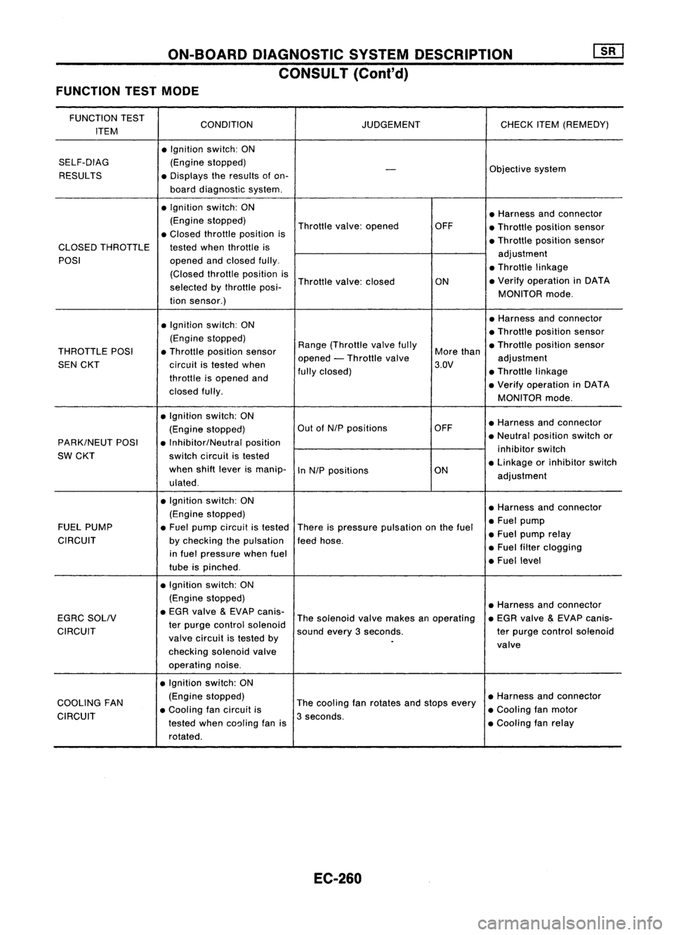
ON-BOARDDIAGNOSTIC SYSTEMDESCRIPTION
CONSULT (Conl'd)
FUNCTION TESTMODE
FUNCTION TEST
CONDITION JUDGEMENTCHECKITEM(REMEDY)
ITEM
•Ignition switch:ON
SELF-DIAG (Enginestopped)
Objectivesystem
-
RESULTS •Displays theresults ofon-
board diagnostic system.
• Ignition switch:ON
•Harness andconnector
(Engine stopped)
Throttlevalve:opened OFF
•Throttle position sensor
• Closed throttle position is
•Throttle position sensor
CLOSED THROTTLE testedwhenthrottle is
POSI opened
andclosed fully. adjustment
• Throttle linkage
(Closed throttleposition is
Throttle valve:closed
ON•
Verify operation inDATA
selected bythrottle posi-
MONITORmode.
tion sensor.)
• Ignition switch:ON •
Harness andconnector
• Throttle position sensor
(Engine stopped)
Range(Throttle valvefully •Throttle position sensor
THROTTLE POSI•Throttle position sensor
opened-Throttle valve More
than
adjustment
SEN CKT circuitistested when 3.QV
throttle isopened and fully
closed) •Throttle linkage
• Verify operation inDATA
closed fully.
MONITORmode.
• Ignition switch:ON
•Harness andconnector
(Engine stopped) Out
ofN/P positions OFF
PARK/NEUT POSI•Inhibitor/Neutral position •
Neutral position switchor
SW CKT switch
circuit istested inhibitor
switch
when shiftlever ismanip-
InN/P positions ON•
Linkage orinhibitor switch
ulated . adjustment
• Ignition. switch:ON
•Harness andconnector
(Engine stopped)
•Fuel pump
FUEL PUMP •Fuel pump circuit istested
Thereispressure pulsation onthe fuel
•Fuel pump relay
CIRCUIT bychecking thepulsation feedhose.
in fuel pressure whenfuel •
Fuel filter clogging
tube ispinched . •
Fuel level
• Ignition switch:ON
(Engine stopped)
•Harness andconnector
EGRC SOLIV •
EGR valve
&
EVAP canis-
Thesolenoid valvemakes anoperating •
EGR valve
&
EVAP canis-
CIRCUIT ter
purge control solenoid
soundevery3seconds. terpurge control solenoid
valve circuit istested by
.
valve
checking solenoidvalve
operating noise.
• Ignition switch:ON
COOLING FAN (Engine
stopped)
Thecooling fanrotates andstops every •
Harness andconnector
• Cooling fancircuit is •Cooling fanmotor
CIRCUIT testedwhencoaling fanis3
seconds.
•Cooling fanrelay
rotated.
EC-260