1995 NISSAN ALMERA N15 relay
[x] Cancel search: relayPage 774 of 1701
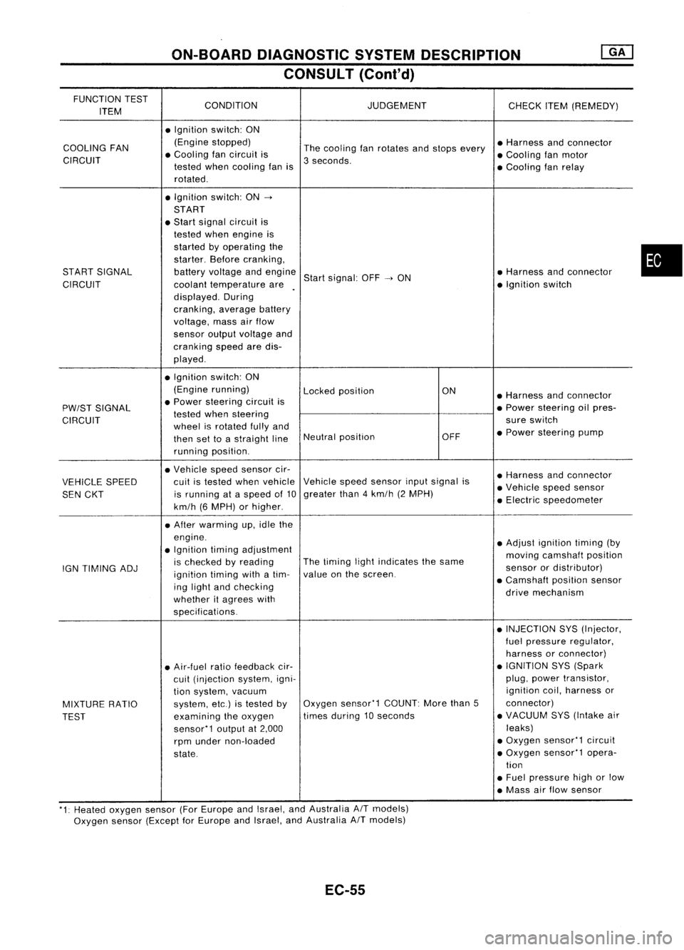
ON-BOARDDIAGNOSTIC SYSTEMDESCRIPTION
CONSULT (Conl'd)
FUNCTION TEST
CONDITION JUDGEMENT
ITEM CHECK
ITEM(REMEDY)
• Ignition switch:ON
COOLING FAN (Engine
stopped)
Thecooling fanrotates andstops every •
Harness andconnector
CIRCUIT •
Cooling fancircuit is
3seconds. •
Cooling fanmotor
tested whencooling fanis
•Cooling fanrelay
rotated .
• Ignition switch:ON-.
START
• Start signal circuit is
tested whenengine is
started byoperating the
starter. Beforecranking,
START SIGNAL batteryvoltage andengine
Startsignal: OFF-.ON •
Harness andconnector
CIRCUIT coolanttemperature are •
Ignition switch
displayed. During
cranking, averagebattery
voltage, massairflow
sensor outputvoltage and
cranking speedaredis-
played .
• Ignition switch:ON
(Engine running)
Lockedposition ON
•Harness andconnector
PW/ST SIGNAL •
Power steering circuitis
•Power steering oilpres-
tested whensteering
CIRCUIT wheelisrotated fullyand sure
switch
then settoastraight lineNeutral
position OFF•
Power steering pump
running position.
• Vehicle speedsensor cir-
•Harness andconnector
VEHICLE SPEED cuit
istested whenvehicle Vehicle
speedsensor inputsignal is
•Vehicle speedsensor
SEN CKT is
running ataspeed of10 greater
than4km/h (2MPH)
•Electric speedometer
km/h (6MPH) orhigher .
• After warming up,idle the
engine. •Adjust ignition timing(by
• Ignition timingadjustment
movingcamshaft position
IGN TIMING ADJ is
checked byreading The
timing lightindicates thesame
sensorordistributor)
ignition timingwithatim- value
onthe screen.
•Camshaft positionsensor
ing light andchecking
drivemechanism
whether itagrees with
specifications.
•INJECTION SYS(Injector,
fuel pressure regulator,
harness orconnector)
• Air-fuel ratiofeedback cir- •
IGNITION SYS(Spark
cuit (injection system,igni- plug,
power transistor,
tion system, vacuum ignition
coil,harness or
MIXTURE RATIO system,
etc.)istested byOxygen
sensor'1 COUNT:Morethan5 connector)
TEST examining
theoxygen times
during 10seconds •
VACUUM SYS(Intake air
sensor'1 outputat2,000 leaks)
rpm under non-loaded •
Oxygen sensor'1 circuit
state. •
Oxygen sensor'1 opera-
tion
• Fuel pressure highorlow
• Mass airflow sensor
'1: Heated oxygen sensor(ForEurope andIsrael, andAustralia AITmodels)
Oxygen sensor(Except forEurope andIsrael, andAustralia
A/T
models)
EC-55
•
Page 783 of 1701
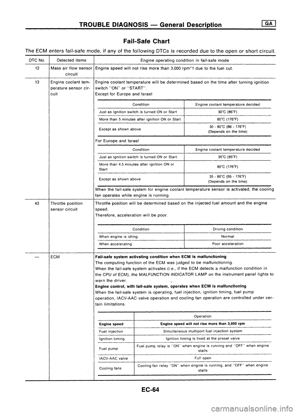
TROUBLEDIAGNOSIS -General Description
Fail-Safe Chart
The ECM enters fail-safe mode,ifany ofthe following DTCsisrecorded duetothe open orshort circuit.
DTC No. Detected
items
Engineoperating conditioninfail-safe mode
12 Massairflow sensor
Enginespeedwillnotrise more than3,000 rpm*1 duetothe fuel cut.
circuit
13 Engine
coolant tem-
Engine coolant temperature willbedetermined basedonthe time after turning ignition
perature sensorcir-switch "ON"or"START".
cuit ExceptforEurope andIsrael
Condition Enginecoolant temperature decided
Just asignition switchisturned ONorStart 30'C(B6'F)
More than5minutes afterignition ONorStart BO'G
(176'F)
Except asshown above 30
-BO'C (B6-176'F)
(Depends onthe time)
For Europe andIsrael
Condition Enginecoolant temperature decided
Just asignition switchisturned ONorStart 35'C
(95'F)
More than4.5minutes afterignition ONor
BO'G(176'F)
Start
Except asshown above 35
-BO'C (95-176'F)
(Depends onthe time)
When thefail-safe systemforengine coolant temperature sensorisactivated, thecooling
fan operates whileengine isrunning.
43 Throttle position Throttle
position willbedetermined basedonthe injected fuelamount andtheengine
sensor circuit speed.
Therefore, acceleration willbepoor.
Condition Driving
condition
When engine isidling Normal
When accelerating Poor
acceleration
-
ECM
Fail-safe
systemactivating conditionwhenECMismalfunctioning
The computing functionofthe ECM wasjudged tobe malfunctioning.
When thefail-safe systemactivates (i.e.,ifthe ECM detects amalfunction conditionin
the CPU ofECM), theMALFUNCTION INDICATORLAMPonthe instrument panellightsto
warn thedriver.
Engine control, withfail-safe system,operates whenECMismalfunctioning
When thefail-safe systemisoperating, fuelinjection, ignitiontiming,fuelpump
operation, IACV-AACvalveoperation andcooling fanoperation arecontrolled undercer-
tain limitations.
Operation
Engine speed Engine
speed
will
notrise more than3,000 rpm
Fuel injection Simultaneous
multipartfuelinjection system
Ignition timing Ignition
timingisfixed atthe preset valve
Fuel pump Fuel
pump' relayis"ON" when engine isrunning and"OFF" whenengine
stalls
IACV-AAG valve Full
open
Cooling fans Cooling
fanrelay "ON" whenengine isrunning, and"OFF" whenengine
stalls
EC-64
Page 798 of 1701
![NISSAN ALMERA N15 1995 Service Manual TROUBLEDIAGNOSES -General Description @K]
ECM Terminals andReference Value(Conl'd)
ECM INSPECTION TABLE-GA16DE forAustralia
Specification dataarereference valuesandaremeasured betweeneachterminal NISSAN ALMERA N15 1995 Service Manual TROUBLEDIAGNOSES -General Description @K]
ECM Terminals andReference Value(Conl'd)
ECM INSPECTION TABLE-GA16DE forAustralia
Specification dataarereference valuesandaremeasured betweeneachterminal](/manual-img/5/57349/w960_57349-797.png)
TROUBLEDIAGNOSES -General Description @K]
ECM Terminals andReference Value(Conl'd)
ECM INSPECTION TABLE-GA16DE forAustralia
Specification dataarereference valuesandaremeasured betweeneachterminal and
@
(ECCS ground).
TER- WIRE
MINAL ITEM
CONDITION DATA
NO. COLOR
[Efl9ineisrunning.
I
0.3-0.6V
L Idle speed
1
WIB
Ignitionsignal
I
Engine isrunning.
I
L Engine speedis2,000 rpm. Approximately
0.9V
2
GYIR
Ignition
check IEngine
isrunning.
I
Approximately12V
L Idle speed
3 LIB Tachometer [Engine
isrunning.
I
Approximately0.9V
L Idle speed
IEngine isrunning.
I
Ilgnition switch"OFF'.'
0-1V
4
WIG
ECCS
relay(Self-shut- L
For afew seconds afterturning ignition
off) switch
"OFF"
Ilgnition switch"OFF"
I
BATTERYVOLTAGE
L Afew seconds passedafterturning ignition
(11-14V)
switch "OFF"
Ilgnition switch"ON"
I
L For 5seconds afterturning ignition switch
0.07-0.20V
"ON"
8
BIP Fuel
pump relay I
Engine isrunning.
I
Ilgnition switch"ON"
I
BATTERYVOLTAGE
L More than5seconds afterturning ignition
(11-14V)
switch "ON"
10
BIW
ECCSground IEngine
isrunning.
I
Engineground
L Idle speed
IEngine isrunning.
I
BATTERYVOLTAGE
Cooling fanrelay ~Cooling fanisnot operating.
(11-14V).
13 LG
(Highspeed: For
AIT
Cooling
fanisoperating atlow speed.
models)
I
Engine isrunning.
I
L Cooling fanisoperating athigh speed. Approximately
OV
IEngine isrunning.
I
BATTERYVOLTAGE
Cooling fanrelay L
Cooling fanisnot operating. (11-14V)
14 LGIR
(Lowspeed)
I
Engine isrunning.
I
L_
Cooling fanisoperating. 0.07
-0.30V
I
Engine isrunning.
I
L Both
AIC
switch andblower switchare 0.08
-0.2V
15
Y
Air
conditioner relay "ON".
IEngine isrunning.
I
BATTERYVOLTAGE
LAIC switchis"OFF". (11
-14V)
EC-79
•
Page 800 of 1701
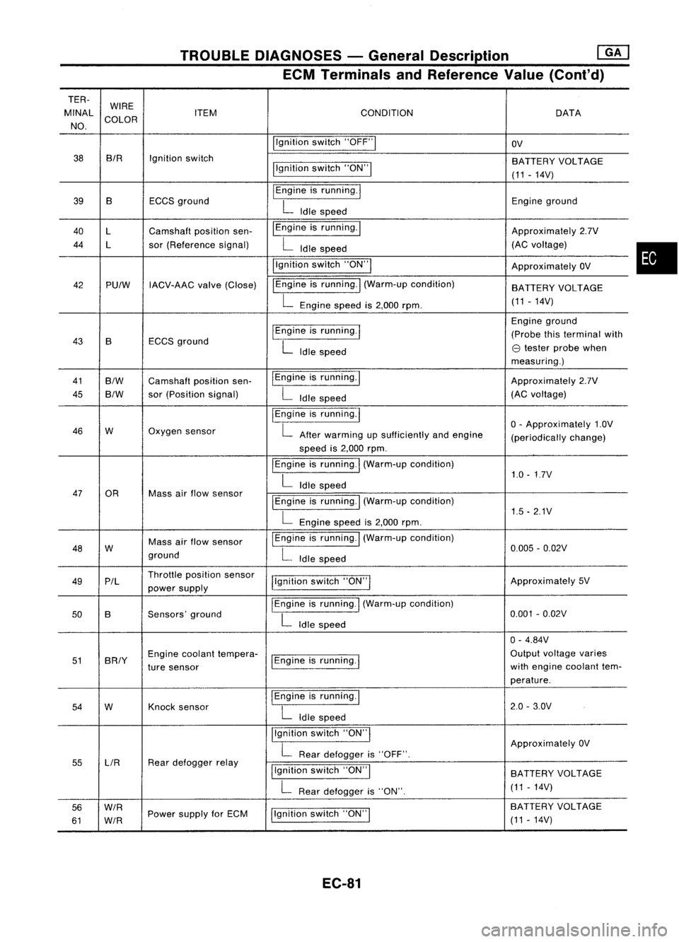
TROUBLEDIAGNOSES -General Description ~
ECM Terminals andReference Value(Cont'd)
TER-
MINAL WIRE
CONDITION
ITEM DATA
NO. COLOR
Ilgnitionswitch"OFF"1
OV
38 BIR
Ignitionswitch
BATTERYVOLTAGE
llgnition switch"ON"!
(11-14V)
39 B ECCSground
I
Engine isrunning.
I
Engineground
L
Idle speed
40 l Camshaft positionsen- I
Engine isrunning. I
Approximately2.7V
44 l sor(Reference signal)
L
Idle speed (AC
voltage)
i'gnition switch"ON'"
ApproximatelyOV
42 PUlW IACV-AAC valve(Close) IEngine
isrunning.
I
(Warm-up condition)
BATTERYVOLTAGE
L
Engine speedis2,000 rpm. (11
-14V)
I
Engine isrunning.
I
Engine
ground
43 B ECCS
ground (Probe
thisterminal with
L
Idle speed
e
tester probe when
measuring.)
41
B/W
Camshaft positionsen- IEngine
isrunning.1
Approximately2.7V
45
B/W
sor
(Position signal)
L
Idle speed (AC
voltage)
I
Engine isrunning.
I
o-
Approximately 1.0V
46 W Oxygen
sensor
L
After warming upsufficiently andengine
(periodicallychange)
speed is2,000 rpm.
I
Engine isrunning.
I
(Warm-up condition)
1.0-1.7V
L
Idle speed
47 OR Massairflow sensor
I
Engine isrunning.! (Warm-up condition)
L
Engine speedis2,000 rpm. 1.5
-2.1V
48 W Mass
airflow sensor
I
Engine isrunning. I(Warm-up condition)
0.005-0.02V
ground
L
Idle speed
49 P/l Throttle
position sensor
j!gnitionswitch"ON"I Approximately
5V
power supply
50 B Sensors'
ground
I
Engine isrunning.
I
(Warm-up condition)
0.001-0.02V
L
Idle speed
0-4.84V
51 BRIY Engine
coolant tempera-
1Engine isrunning.
I
Output
voltage varies
ture sensor with
engine coolant tem-
perature.
54 W Knock
sensor
I
Engine isrunning.!
2.0-3.0V
L
Idle speed
Ilgnition switch"ON'"
ApproximatelyOV
L
Rear defogger is"OFF".
55 LlR Rear
defogger relay
Ilgnitionswitch"ON"I
BATTERY VOLTAGE
L
Rear defogger is"ON". (11
-14V)
56
W/R
Ilgnitionswitch"ON"I BA
TTERY VOLTAGE
61
W/R
Power
supply forECM
(11-14V)
EC-81
•
Page 802 of 1701
![NISSAN ALMERA N15 1995 Service Manual TROUBLEDIAGNOSES -General Description @K]
ECM Terminals andReference Value(Conl'd)
ECM INSPECTION TABLE-Except GA16DE forAustralia
Specification dataarereference valuesandaremeasured betweeneacht NISSAN ALMERA N15 1995 Service Manual TROUBLEDIAGNOSES -General Description @K]
ECM Terminals andReference Value(Conl'd)
ECM INSPECTION TABLE-Except GA16DE forAustralia
Specification dataarereference valuesandaremeasured betweeneacht](/manual-img/5/57349/w960_57349-801.png)
TROUBLEDIAGNOSES -General Description @K]
ECM Terminals andReference Value(Conl'd)
ECM INSPECTION TABLE-Except GA16DE forAustralia
Specification dataarereference valuesandaremeasured betweeneachterminal and
@
(ECCS ground).
TERMINAL WIRE
NO. COLOR ITEM
CONDITION DATA
IEngine isrunning.1
0.2-0.3V
L
Idle speed
1
WIB
Ignitionsignal
IEngineisru~
L
Engine speedis2,000 rpm. Approximately
0.7V
Tachometer IEngineisrunning.1
2 LIB
(Modelswithtachome-
L
Idle speed 0.7
-0.9V
ter)
3 GYIR
Ignitioncheck jEngine
isrunning.1
Approximately13V
L
Idle speed
Engine isrunning.'
I
Ignition switch"OFF"I
0-1V
ECCS relay(Self-shut-
L
For afew seconds afterturning ignition
4
WIG
off) switch
"OFF"
llgnition switch"OFF"I
BATTERYVOLTAGE
L
Afew seconds afterturning ignition
(11-14V)
switch "OFF"andthereafter
IEngine isrunning.1
BATTERYVOLTAGE
Cooling fanrelay (Low
L
Cooling fanisnot operating. (11-14V)
9 LGIR
speed) IEngineisrunning.1
L
Cooling fanisoperating. Approximately
OV
IEngine isrunning.1
BATTERYVOLTAGE
Cooling fanrelay (High
t
Cooling fanisnot operating.
(11-14V)
10 LG Cooling
fanisoperating atlow speed.
speed) IEngineisrunning.1
L
Cooling fanisoperating athigh speed. Approximately
OV
IEngine isrunning.1
L
Both
AIC
switch andblower fanswitch Approximately
OV
11 Yor
GAir
conditioner relay are
"ON".
IEngine isrunning.1
BATTERYVOLTAGE
LAIC
switchis"OFF". (11
-14V)
IEngine isrunning.1
BATTERYVOLTAGE
VTC solenoid valve
L
Idle speed (11
-14V)
12 YIR (GA
16DE engine mod-
IEngineisrunning.1
els except forEurope
and Israel)
L
Engine isracing quickly fromidleto4,000 Approximately
OV
rpm at1st position.
EC-83
•
Page 805 of 1701
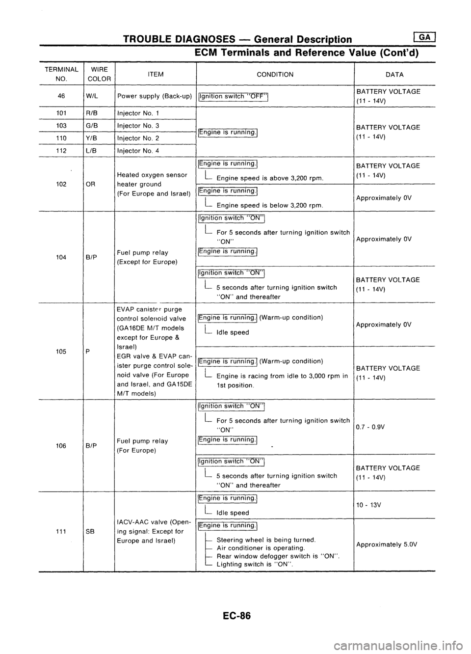
TROUBLEDIAGNOSES -General Description
mJ
ECM Terminals andReference Value(Cont'd)
TERMINAL WIRE
NO. COLOR ITEM
CONDITION DATA
46 WIL Powersupply (Back-up)
Ilgnitionswitch"OFF'" BA
TTERY VOLTAGE
(11 -14V)
101 RIB InjectorNo.1
103
GIB
InjectorNo.3
BATTERYVOLTAGE
110 Y/B InjectorNO.2 IEngine
isrunning./
(11-14V)
112 LIB Injector
NO.4
IEngineisrunning.1
BATTERY VOLTAGE
Heated oxygen sensor
L
Engine speedisabove 3,200rpm. (11
-14V)
102 OR heaterground
(For Europe andIsrael) IEngine
isrunning.1
ApproximatelyOV
L
Engine speedisbelow 3,200rpm.
jlgnition switch"ON"I
L
For 5seconds afterturning ignition switch
"ON" Approximately
OV
104 B/P Fuel
pump relay /Engine
isrunning.1
(Except forEurope)
Ilgnitionswitch"ON"I
BATTERYVOLTAGE
L
5seconds afterturning ignition switch
(11-14V)
"ON" andthereafter
EVAP canister purge
control solenoid valveIEngine
isrunning.1 (Warm-up condition)
(GA16DE
MIT
models
L
Idle speed Approximately
OV
except forEurope
&
105 P Israel)
EGR valve
&
EVAP can-
ister purge control sole-IEngine
isrunning.1 (Warm-up condition)
BATTERYVOLTAGE
noid valve (ForEurope
L
Engine isracing fromidleto3,000 rpmin
(11-14V)
and Israel, andGA15DE
1st position.
MIT
models)
jlgnitionswitch"ON"I
L
For 5seconds afterturning ignition switch
"ON" 0.7
-0.9V
106 SIP Fuel
pump relay IEngine
isrunning.1
(For Europe)
-
Ilgnition switch"ON"I
BATTERYVOLTAGE
L
5seconds afterturning ignition switch
(11-14V)
"ON" andthereafter
IEngine isrunning.1
10-13V
L
Idle speed
IACV-AAC valve(Open-
IEngineisrunning.1
111 5B ingsignal: Exceptfor
Europe andIsrael)
l
51.."" wheel
t,
be'" I,med
Approximately5.0V
Air conditioner isoperating.
Rear window defogger switchis"ON".
Lighting switchis"ON".
EC-86
Page 807 of 1701
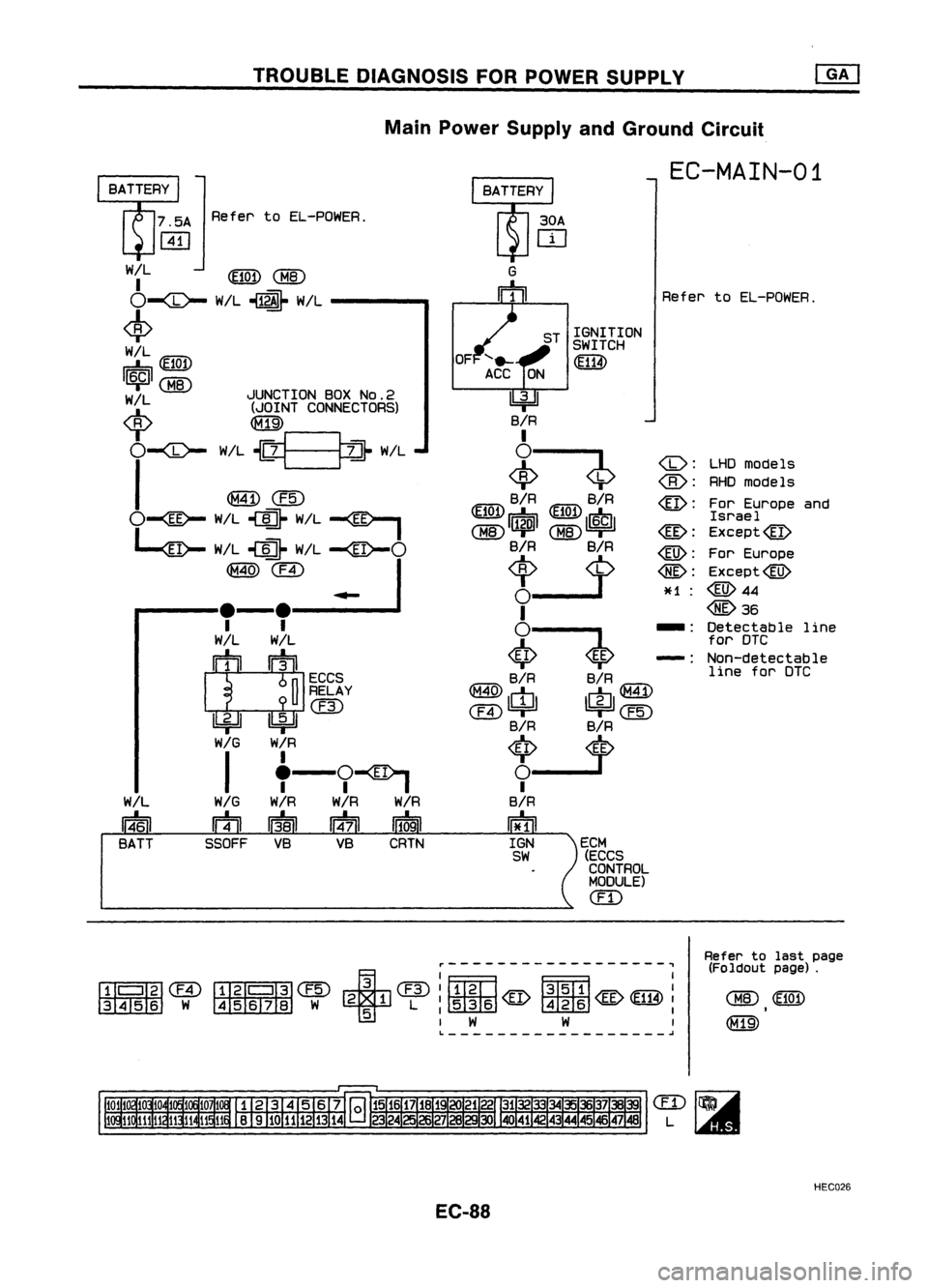
TROUBLEDIAGNOSIS FORPOWER SUPPLY
Main Power Supply andGround Circuit
W/L
14~1
BATT
LHD
models
RHO models
For Europe and
Israel
Except@
For Europe
Except@
@44
@36
Detectable line
for DTC
Non-detectable line forDTC
EC-MAIN-01
Refer toEL-POWER.
(1J:
@:
@:
@:
@:
@:
~H :
-:
-:
ECM (ECCS
CONTROL
MODULE)
em
ST
IGNITION
SWITCH
'iIi'
30A
OJ
G
m
4=Jl
B/R
I
~ ~
B/R B/R
~~1~
laiml
~~1~
1$1
B/R B/R
I
~$
tU"Affi
B/R B/R
tcr:n\
~T T~
@4=U
1bi=U@
B/R B/R
~ __
I
B/R
n*ll
IGN
SW
OF
7.5A
RefertoEL-POWER.
[ill
W~L ~
<:MID
0-<0-
W!L~ W/L--- .....
~
W!L
IE7n7\
d::,~
I~I
/ JUNCTIONBOXNO.2
~ (JOINTCONNECTORS)
"T
0-<0-
W/L~__ ~~ W!L
I
@Jew
O--
~ W/L~ W/L
-
~ (F4) •
I
..... -_,.-.--=--.1
II
W/L W/L
IT
~I
ECCS
~ RELAY
@
lbi=Jl1!:idl
WIG W/R
I
'-9-
WIG W/R W/RW/R
m
I;BI 114'71
11~1
SSOFF VBVBCRTN
~------------------~
fJjlll~@
~'I'fIl@ +@:mm
f3T5m:
3456 W4567B W21L
:~@~@
5
I
W W
I
L ~
Refer
tolast page
(Foldout page).
HEC026
EC-88
Page 809 of 1701
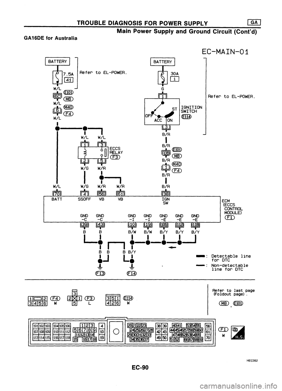
TROUBLEDIAGNOSIS FORPOWER SUPPLY @KJ
Main Power Supply andGround Circuit(Cont'd)
GA16DE forAustralia
EC-MAIN-01
ECM(ECCS
CONTROL
MODULE)
em
Detectable line
for DTC
Non-detectable line forDTC
Refer
toEL-POWER.
-:
-:
ST
IGNITION
SWITCH
~
30A
IT]
I4J
B/R
I
B/R tE77\i\
r=:b~
I~I
B/R
tm'i'\\
cb~
'4=ll@
B/R
I
B/R
~
IGN
SW
Refer
toEL-POWER.
GND GND GNDGNDGND GNDGND
-C -C -I -I -E -E-E
13.9
I
I~31 ~~ n1~6111~21111:81
B B B/WB/W B/YB/YB/Y
L
I II II I
, I_I
,-e-e-=e---J
B B BB/Y
~..I L~
-!-
-!
CF13)
ffi
7.5A
~
W/L
tE77\i\
r=:b~
I~ICMID
W/L
IctJl~
=r@
W/L
I
e,--,,-,
W/LW/L
IT
~I
ECCS
~ RELAY
@
lbf=n~
WIG
W/R
I "__ ~
WIG
W/R W/R
m
1I~61
If6TI
SSOFF VBVB
W/L
17~1
BATT
III'
I
'liJ
(ffi ~ @
3456 W
T
L~~
t3RIID
W
Refer
tolast page
(Foldout page).
101 102103
107 108 109
113
114115 104
105 106
110 111112
116
117
118
HEC062
EC-90