1995 NISSAN ALMERA N15 relay
[x] Cancel search: relayPage 641 of 1701
HARNESSLAYOUT
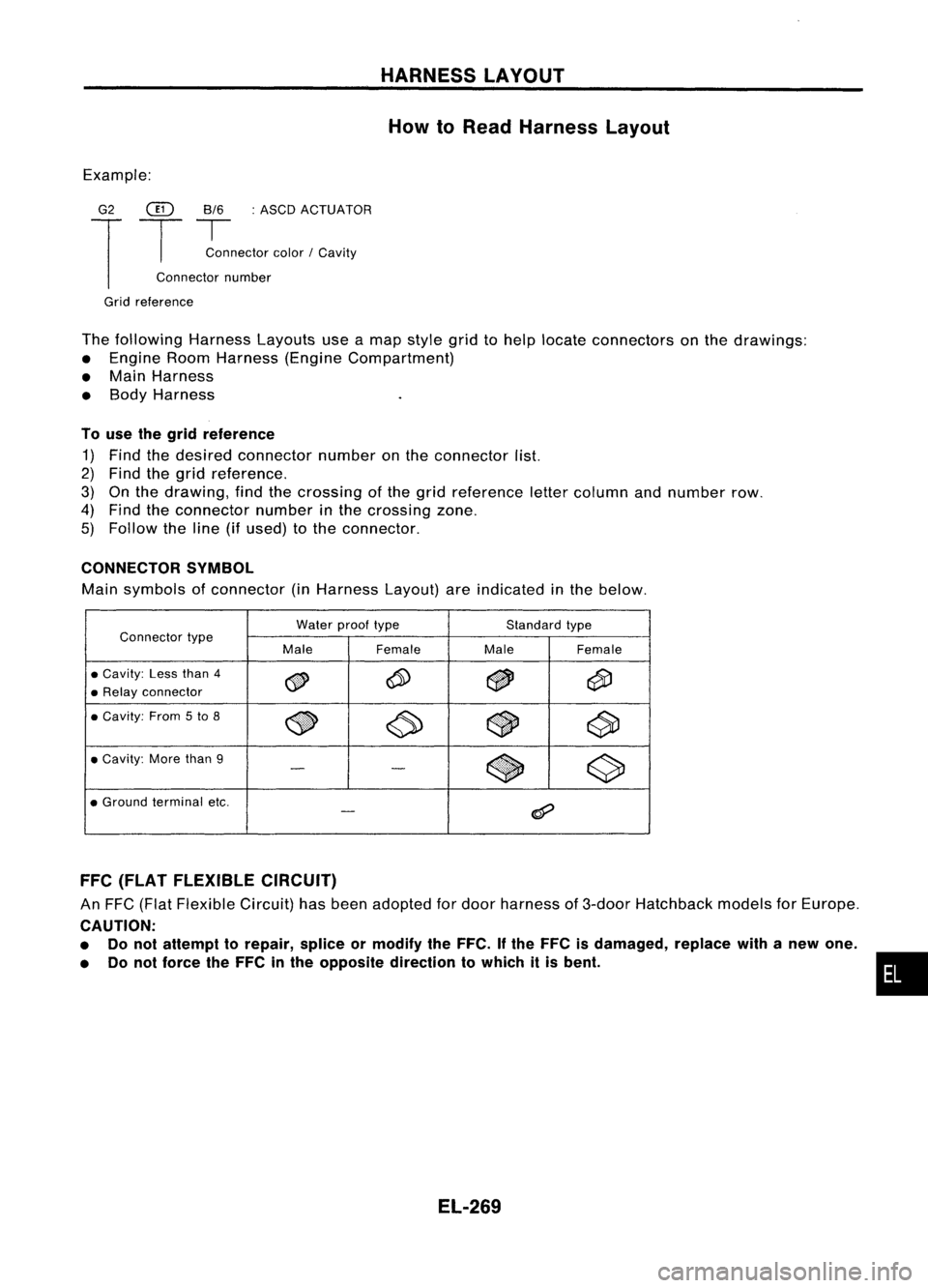
How toRead Harness Layout
Example:
G2
@
8/6:ASCD ACTUATOR
T
T
~nector color/Cavity
Connector number
Grid reference
The following HarnessLayoutsuseamap style gridtohelp locate connectors onthe drawings:
• Engine RoomHarness (EngineCompartment)
• Main Harness
• Body Harness
To use thegrid reference
1) Find thedesired connector numberonthe connector list.
2) Find thegrid reference.
3) Onthe drawing, findthecrossing ofthe grid reference lettercolumn andnumber row.
4) Find theconnector numberinthe crossing zone.
5) Follow theline (ifused) tothe connector.
CONNECTOR SYMBOL
Main symbols ofconnector (inHarness Layout)areindicated inthe below.
Water prooftype Standardtype
Connector type
MaleFemale MaleFemale
•
Cavity:
Lessthan
4
~ ~
~
@i)
•
Relay
connector
•
Cavity:
From
5
to
8
~ ~~
c90
•
Cavity:
Morethan
9
$
~
-
-
•
Ground
terminal etc.
@?
-
FFC (FLAT FLEXIBLE CIRCUIT)
An FFC (Flat Flexible Circuit)hasbeen adopted fordoor harness of3-door Hatchback modelsforEurope.
CAUTION:
• Donot attempt torepair, spliceormodify theFFC. Ifthe FFC isdamaged, replacewithanew one.
• Donot force theFFC inthe opposite direction towhich itis bent.
EL-269
•
Page 730 of 1701
ENGINEANDEMISSION CONTROL OVERALLSYSTEM
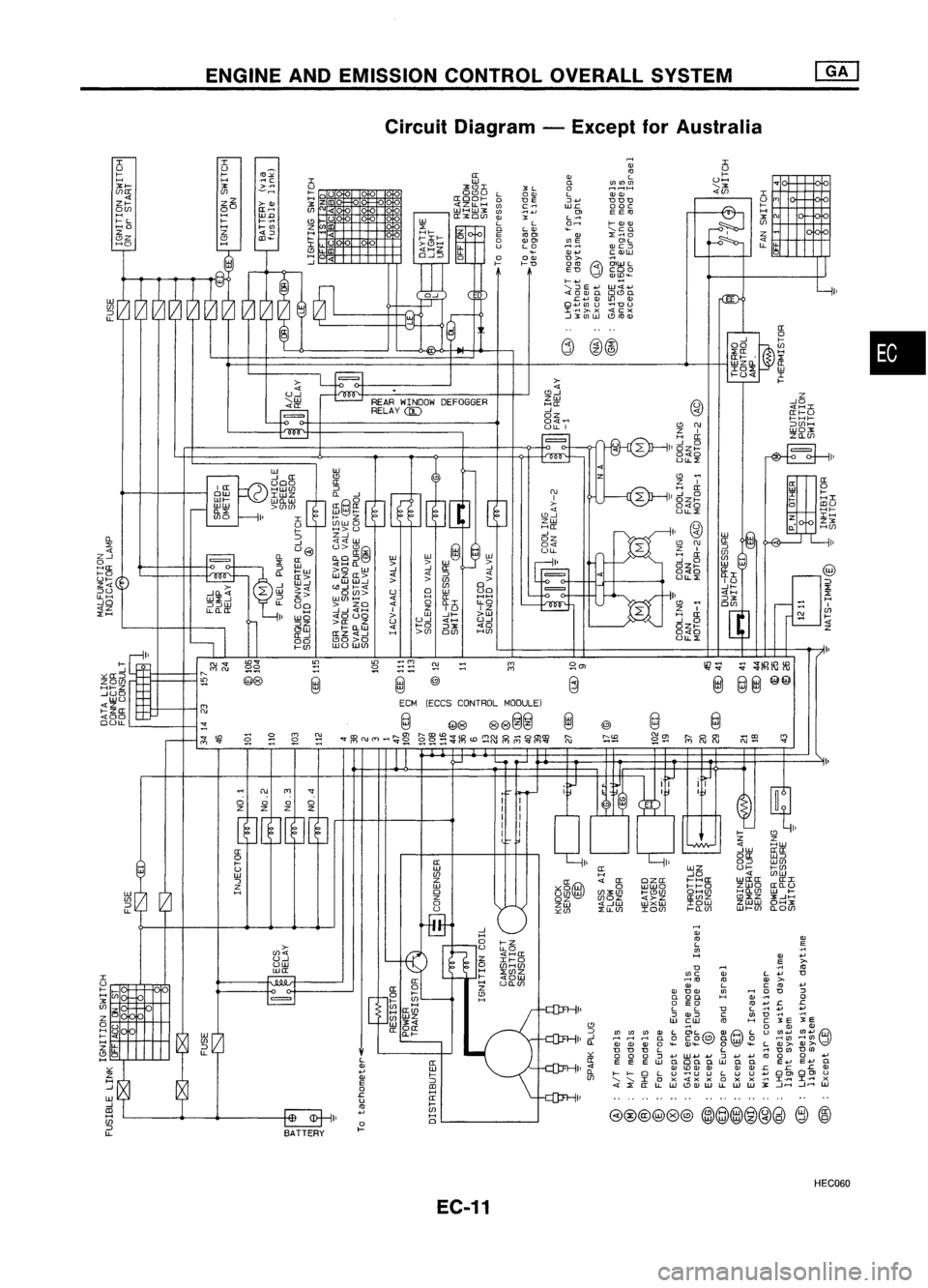
Circuit Diagram -Except forAustralia
•
-11
I'
a:
([
0
W
l-
I
I-
HI
0
alU
HI-
Z IH
ZX
a:
HffJ
Z
--'0
4HI
([I-U
I-HI-
::>ffJH
WOX
ZIl-ffJ
W
.~
....
>-
D
:J
o
1:. 1:.
~ ~
3:
E
3:
E
W W
(1)+.1
Ul+J
tW"\
~~ ~~\::Y
'0
(I)
U(/)
o
0....
E+.J E+J
a
I:. I:.
ll>
DC) 00l U
I ..... I..... X
...Jr-l ...J..-t
lLJ
>-@--
L-jl'
I
U
I-
UH
...
'-X
'"
r--.
I-
H
~
X
'"
Ul
Z
~
4
u.
LL
~
H
'"
L
(I)
H
D
H
we
(l) '-
..-110
co
Q)
W L C
~~ ~
~.~
E~
"tJ~~
W;:) CUl
u
.SlLJ
ro
H
5
OlL,;;;-, W!H\LU
~.e'8t
~G.e .~
WoI-J
+J
:J
+J
+J
co
oaowoc.
ill
III CLl
Q.l
Q.l
.c
....... uULuU+J
C!)QJwu.L1JUJ~
~L-
:s
06
j):Ji
:>:([ H
lIt-. ~
LUZo..
a:
IO~
w
....u«
I
_,- I-
[ft('" ~
" CD
C\J
L
ZI
H ([
...J 0
OZI-
040
ULL:>:
~--ll'
CD~
" ZI
L
H([
...J 0
OZI-
040
ULL:>:
OJ
Cl
0
L
:J
'"
UJ
::>
(I)(I) (I)
ll>
L
...J
HH
H
0
0
Il-
ll>ll>
ll>
0
~
'"
D
D
D L
0 0
0:J
....
([
EEEUJ
0
4
ll>
ll-
l-
I-
0
LU
ffJ
'-'-
I
0
x
4 :>:
([
LLW
~en
LlJ-
:;;
~~~~
"''''
~
@
@@
@@
@
@
@
@
hi
r;:;;s
"'en
{;)
@R)
_
CD
'"
~~
"'-
'"
I'
itJ
.:--1
iY
II
@
I
I
~
EI
bJ ~~
CD
I'
Z
HUJ
([([
0([ UJ::>
I'
I'
0::>
WffJ
([
WZUI-
I-ffJ
H --'04
ffJUJ
~g@)
4
a: oza: I-Ha:
wa:a:([I
0 wUJO 1-1-0 ZUJO
([Il-U
UffJ UJ ffJXffJ
....CDffJ OHffJ HIl-ffJ
w
I-
OZ ffJOZ
4>-Z
a:UlZ
"':>:zX..JH
ZUJ 4--'UJ
WXW IOUJ
ZUJwOHX
"'Ul :>:LLffJ
IOffJ I-Il-Ul Wl-Ul
O-OUl
~
1
1'
--<..r
~
I'
--<..r
~
--<..r
I'
~
I'
--u
>-
4
CD--'
ZW
Ha:
--'
OZ
04~
~
~
H
OJ
'"
L
"L
Cl
~~~
0
L OOJ LOJOJ
0 1:JE :J.... DDD
(I)
.~::
WI:.
ooc
(I)
OlEE
"
L'~
L LOH
>-OJOJ
0
LOJ
~
'-co
E
0 OJ'"
~.~
OlL
U L,2 OJC:J
OJ ....
.~Q)W
0 OOJ D>-
>- >-D
0
G)
OlUJ
L
ED cOo
OJlD~
>- ....
UJ4....
'-..::lE+J
4:
0
QJ
0.
OCDo
I:. ....
OJ
LlJ
OJ
O+J UlU
~DU
I.rl;>.
x
4Cx
.-I~(I)W
CD
..
..
G)
@@
,..J
L
o-J
I ,
I I
I I
I I
!
I
-
d
@)
@
ECM (ECCS CONTROL MODULE)
BATTERY
~
LtBf- .
~m
L.:-:.:.-J
REARWINDOW DEFOGGER
~ RELAY@)
,"0
-
~([
~
Ii!>
>-
=0:00 ([
I
a::
2
HW(J)
::J
mil
C\J
ow
IWZ
o..-.J
~ ~~ ~8itJJ
[!J
ffi@~
0
OJ
I
II
>-
4
UJO --HI
I
t--
Z
CD--'
ZW
_ U(J)WO
H([
I- H>U
--'
:3
~
oz
U@I U>~@
@
@w 04
ULL
=
0-
([ O-O::>~ ww
la=
:>:
w
«H
Q.
>>
ll! -
:J
::J
b:~
GJ~
ffi~
--'
...J
~
0-
4
::J
ffJ >
2:
--'
~
~c5
tn~
ffJ
°
--'0-4 W
U
:3
w
uo
UJ:>:--' ::>
5> ~Ul
20
([
HH
::>::>w LL
LLIl-([
u8
-.J....J
«H
I
Z
IU IZ
~
I'
wo
<£0UO
>W
--'>- >w
l
5~
~~~~
U
U...J
4H
U--'
4 >-0
::>X 40
H >ffJ
OUl HffJ
I
~~
illS
Gj@
"'''' lD'"
~
"-
co
'"
~s:
~
@e
@
co
'"
;'!;
r--- ~
~
~~
co
!,;l
~
~
C\J
'"
'"
0 00
0
Z ZZ
Z
" II
II I
([
@
0
>- U
W
-,
~0 [~
3
>-
ffJ
uw
~
I
=
I
U
I-
tii
H
X
ffJ
IS
Z
0 U
H
>i
>-
H LL
Z LL
CD
0
H
~r;
",a:::>
ZOffJ
HI-Z
--'UO
UJU
4Z
>-Za:
400
OULL
0-
:>:
4
Z--'
o
Ha: >-0
~'::(0)
::>U
LLH
--'0
4Z
:>:H
HEC060
EC-11
Page 742 of 1701
ENGINEANDEMISSION BASICCONTROL SYSTEMDESCRIPTION
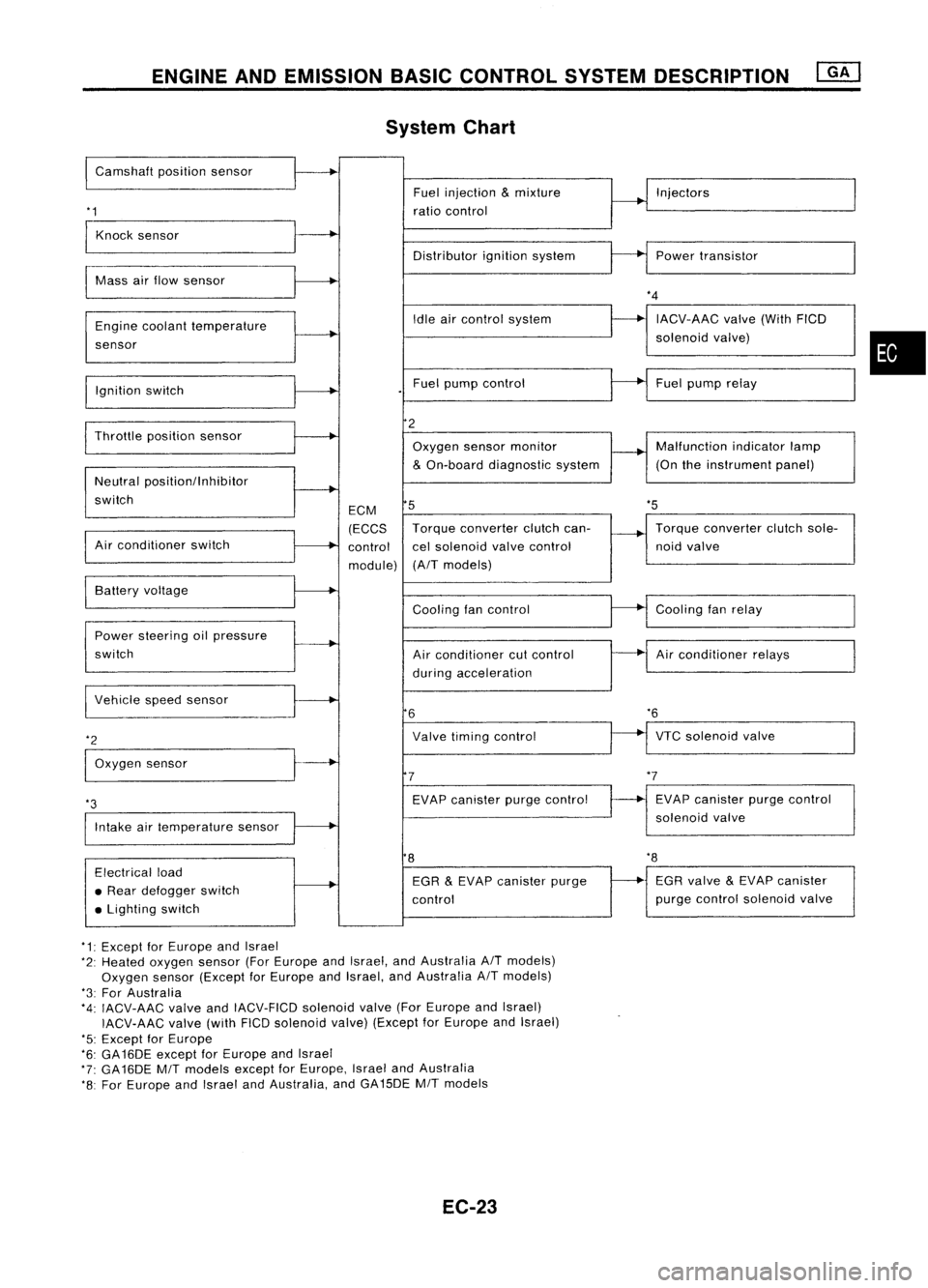
System Chart
I
Camshaft positionsensor
'1
Fuel
injection
&
mixture
ratio control Injectors
Knock sensor
Distributorignitionsystem Powertransistor
Mass airflow sensor
Engine coolant temperature
sensor
Ignition switch Idle
aircontrol system
Fuel pump control
*4
IACV-AAC valve(WithFICD
solenoid valve)
Fuel pump relay
•
'5
Throttle
positionsensor
Neutral positionllnhibitor
switch
Air conditioner switch ECM
(ECCS
control
module)
2
Oxygen sensormonitor
&
On-board diagnostic system
5
Torque converter clutchcan-
cel solenoid valvecontrol
(A/T models) Malfunction
indicatorlamp
(On theinstrument panel)
Torque converter clutchsole-
noid valve
VTC solenoid valve
*6
Air
conditioner relays
Cooling
fanrelay
EVAP canister purgecontrol
solenoid valve
Cooling
fancontrol
Air conditioner cutcontrol
during acceleration
Valve timing control
EVAP canister purgecontrol
7
6
Power
steering oilpressure
switch Battery
voltage
Intake airtemperature sensor
*3
I
Vehicle speedsensor
*2
I
Oxygen sensor
8
'8
Electrical load
• Rear defogger switch
• Lighting switch EGR
&
EVAP canister purge
control EGR
valve
&
EVAP canister
purge control solenoid valve
*1: Except forEurope andIsrael
*2: Heated oxygen sensor(ForEurope andIsrael, andAustralia A/Tmodels)
Oxygen sensor(Except forEurope andIsrael, andAustralia A/Tmodels)
*3: For Australia
*4: IACV-AAC valveandIACV-FICD solenoidvalve(ForEurope andIsrael)
IACV-AAC valve(withFICDsolenoid valve)(Except forEurope andIsrael)
'5: Except forEurope
*6: GA16DE exceptforEurope andIsrael
*7: GA16DE MITmodels exceptforEurope, IsraelandAustralia
*8: For Europe andIsrael andAustralia, andGA15DE MITmodels
EC-23
Page 747 of 1701
ENGINEANDEMISSION BASICCONTROL SYSTEMDESCRIPTION ~
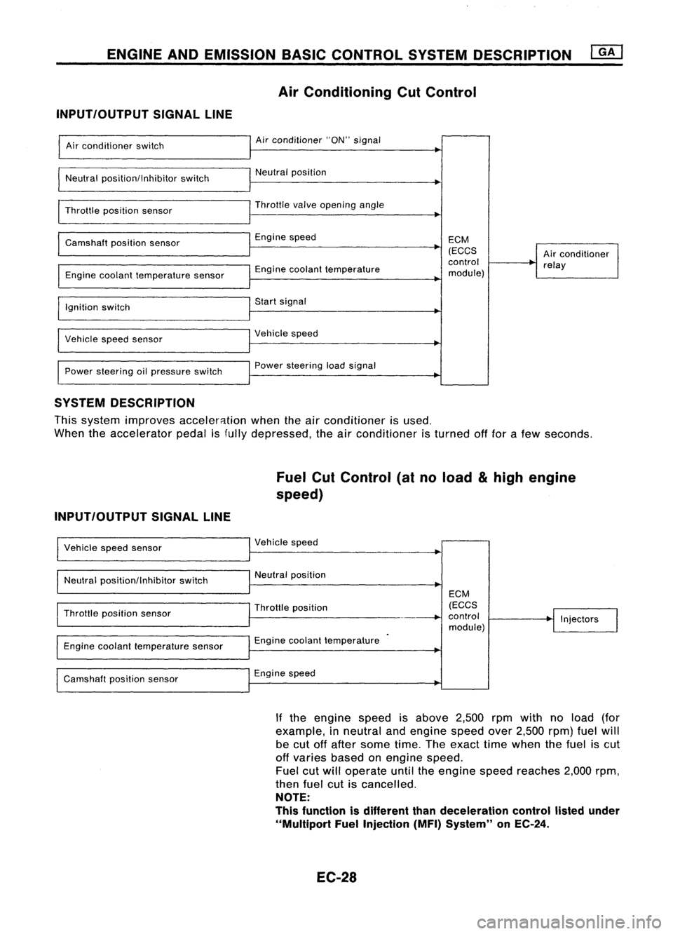
Air Conditioning CutControl
INPUT/OUTPUT SIGNALLINE
Air conditioner switch
Neutral position/Inhibitor switch
Throttle position sensor
Camshaft positionsensor
Engine coolant temperature sensor
Ignition switch
Vehicle speedsensor
Power steering oilpressure switch Air
conditioner "ON"signal
Neutral position
Throttle
valve
opening angle
Engine speed
Engine coolant temperature
Start signal
Vehicle speed
Power steering loadsignal ECM
(ECCS
control
module) Air
conditioner
relay
SYSTEM DESCRIPTION
This system improves acceler8.tion whentheairconditioner isused.
When theaccelerator pedalisfully depressed, theairconditioner isturned offfor afew seconds.
Fuel CutControl (atnoload
&
high engine
speed)
INPUT/OUTPUT SIGNALLINE
Vehicle speedsensor
Neutral position/Inhibitor switchVehicle
speed
Neutral position
Throttle position sensor
Engine coolant temperature sensor
Camshaft positionsensor Throttle
position
Engine coolant temperature
Engine speed ECM
(ECCS
control
module) Injectors
If the engine speedisabove 2,500rpmwith noload (for
example, inneutral andengine speedover2,500 rpm)fuelwill
be cut offafter some time.Theexact timewhen thefuel iscut
off varies basedonengine speed.
Fuel cutwill operate untiltheengine speedreaches 2,000rpm,
then fuelcutiscancelled.
NOTE:
This function isdifferent thandeceleration controllistedunder
"Multiport FuelInjection (MFI)System" onEC-24.
EC-28
Page 768 of 1701
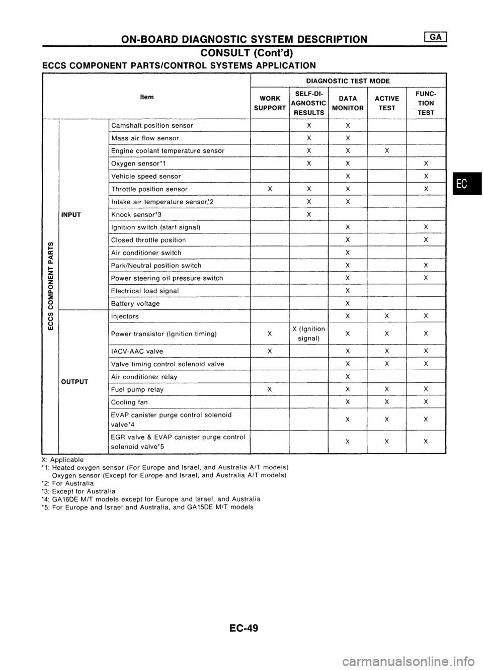
ON-BOARDDIAGNOSTIC SYSTEMDESCRIPTION
CONSULT (Cont'd)
ECCS COMPONENT PARTS/CONTROL SYSTEMSAPPLICATION
DIAGNOSTICTESTMODE
Item WORKSELF-DI-
ACTIVEFUNC-
DATA
SUPPORT AGNOSTIC
MONITOR TION
TEST
RESULTS TEST
Camshaft positionsensor
X
X
Mass airflow sensor
X
X
Engine coolant temperature sensor
X
X X
Oxygen sensor'1
X
X X
Vehicle speedsensor
XX
Throttle positionsensor
XX
X X
Intake airtemperature sensor.'2
X
X
INPUT
Knock
sensor'3
X
Ignition switch(startsignal)
XX
I/)
Closed
throttle position
X
X
l-
ll:
Airconditioner switch
X
<
~
Park/Neutralpositionswitch
X
X
I-
Z
UJ
Powersteering oilpressure switch
XX
z
0
Electricalloadsignal
X
~
:E
0
Batteryvoltage
X
u
I/)
Injectors
XX
X
u
u
UJ
X(Ignition
Power transistor (Ignitiontiming) X X
XX
signal)
IACV-AAC valve X
XX
X
Valve timing control solenoid valve XX
X
OUTPUT
Air
conditioner relay
X
Fuel pump relay XX
XX
Cooling fan XX
X
EVAP canister purgecontrol solenoid
XX X
valve'4
EGR valve
&
EVAP canister purgecontrol
XX
X
solenoid valve'5
X: Applicable
'1: Heated oxygen sensor(ForEurope andIsrael, andAustralia AITmodels)
Oxygen sensor(Except forEurope andIsrael, andAustralia AITmodels)
'2: For Australia
'3: Except forAustralia
'4: GA16DE
MIT
models exceptforEurope andIsrael, andAustralia
'5: For Europe andIsrael andAustralia, andGA15DE
MIT
models
EC-49
•
Page 771 of 1701
![NISSAN ALMERA N15 1995 Service Manual ON-BOARDDIAGNOSTIC SYSTEMDESCRIPTION
CONSULT (Coni'd)
Monitored item
ECM
Main
[Unit] input
signals Description
Remarks
signals
LOAD SIGNAL •Indicates [ON/OFF] conditionfromthe
[ON/OFF] reardefo NISSAN ALMERA N15 1995 Service Manual ON-BOARDDIAGNOSTIC SYSTEMDESCRIPTION
CONSULT (Coni'd)
Monitored item
ECM
Main
[Unit] input
signals Description
Remarks
signals
LOAD SIGNAL •Indicates [ON/OFF] conditionfromthe
[ON/OFF] reardefo](/manual-img/5/57349/w960_57349-770.png)
ON-BOARDDIAGNOSTIC SYSTEMDESCRIPTION
CONSULT (Coni'd)
Monitored item
ECM
Main
[Unit] input
signals Description
Remarks
signals
LOAD SIGNAL •Indicates [ON/OFF] conditionfromthe
[ON/OFF] reardefogger signaland/or lighting
switch.
0 0
ON:
Rear defogger isoperating
and/or lighting switchison.
OFF: Rear defogger isnot operating
and lighting switchisnot on.
INJ PULSE [msec]
0
•
Indicates theactual fuelinjection
•When theengine isstopped, acertain
pulse widthcompensated byECM computedvalueisindicated.
according tothe input signals.
IGN TIMING [BTDC]
0
•
Indicates theignition timingcomputed
by ECM according tothe input sig-
nals.
IACV-AACIV
[%]
•Indicates theidle aircontrol valve
0
(AAC
valve) control valuecomputed
by ECM according tothe input sig-
nals.
A/F ALPHA
[%]
•Indicates themean valueofthe air-
•When theengine isstopped, acertain
0
fuel
ratio feedback correction factor valueisindicated.
per cycle. •This data alsoincludes thedata for
the air-fuel ratiolearning control.
AIR COND RLY
0
•
Indicates theairconditioner relay
[ON/OFF] controlcondition (determined byECM
according tothe input signal).
COOLING FAN*2
•Indicates thecontrol condition ofthe
[ON/OFF] or[LOW/
coolingfans(determined byECM
HI/OFF]
0
according
tothe input signal).
ON ...Operating
LOW ...Operates atlow speed
HI ...Operates athigh speed
OFF ...Stopped
FUEL PUMP RLY
0
•
Indicates thefuel pump relaycontrol
[ON/OFF] conditiondetermined byECM accord-
ing tothe input signals.
VALVE TIMSOL*1
•The control condition ofthe valve tim-
[ON/OFF] ingsolenoid valve(determined by
ECM according tothe input signal) is
indicated.
ON ...VTC operating
OFF ...VTC notoperating
EGRC SOLIV (EVAP
•Indicates thecontrol condition ofthe
canister purgecon-
EVAPcanister purgecontrol solenoid
trol solenoid valve valveorEGR valve
&
EVAP canister
or EGR
&
EVAP can- purgecontrol solenoid valve(deter-
ister purge control
0
mined
byECM according tothe input
solenoid valve) signal).
[ON/OFF] ON'"EVAP canister purgeoperation
cut-off OFF ...EVAP canister purgeoperation
not cut-off
VOLTAGE •Voltage measured bythe voltage
[V] probe.
PULSE •Pulse width, frequency orduty cycle •Only "#"isdisplayed ifitem is
[msec] or[Hz] or measuredbythe pulse probe. unable
tobe measured .
[%]
•
Figures with"#"s aretemporary
ones. Theyarethesame figures as
an actual pieceofdata which wasjust
previously measured.
*1: GA16DE exceptforEurope andIsrael
*2: GA16DE engineA/Tmodels forEurope without heavydutykithave a2- step control [ON/OFF] system."LOW"and"HI"
are shown onCONSULT screentorepresent "ON"condition.
EC-52
Page 772 of 1701

ON-BOARDDIAGNOSTIC SYSTEMDESCRIPTION
CONSULT (Cont'd)
ACTIVE TESTMODE
TEST ITEM CONDITION JUDGEMENT
CHECKITEM(REMEDY)
• Engine: Returntothe original
•Harness andconnector
FUEL INJECTION trouble
condition If
trouble symptom disappears,
•Fuel injectors
• Change theamount offuel see
CHECK ITEM.
injection usingCONSULT . •
Oxygen sensor*1
• Engine: Afterwarming up,idle
IACV-AACIV the
engine.
Enginespeedchanges according •Harness andconnector
OPENING •
Change theIACV-AAC valve
tothe opening percent. •
IACV-AAC valve
opening percentusingCON-
SULT.
• Engine: Returntothe original
•Harness andconnector
ENG COOLANT trouble
condition
Iftrouble symptom disappears, •
Engine coolant temperature
TEMP •
Change theengine coolant
.
see CHECK ITEM. sensor
temperature indicationusing
•Fuel injectors
CONSULT.
• Engine: Returntothe original
trouble condition
Iftrouble symptom disappears,
IGNITION TIMING•
Timing light:Set •
Adjust initialignition timing
• Retard theignition timingusingsee
CHECK ITEM.
CONSULT .
• Engine: Afterwarming up,idle •
Harness andconnector
the engine. •
Compression
POWER •
A/C switch "OFF"
Enginerunsrough ordies . •
Injectors
BALANCE •
Shift lever "N" •
Power transistor
• Cut offeach injector signalone •
Spark plugs
at atime using CONSULT. •
Ignition coils
• Ignition switch:ON
COOLING FAN*3•
Turn thecooling fan"ON" and
Cooling fanmoves andstops. •
Harness andconnector
"OFF", or"LOW" and"HI" •
Cooling fanmotor
and "OFF" usingCONSULT .
• Ignition switch:ON(Engine
FUEL PUMP stopped)
Fuelpump relaymakes theoper- •Harness andconnector
• Turn thefuel pump relay"ON"
RELAY and"OFF" usingCONSULT ating
sound. •
Fuel pump relay
and listen tooperating sound.
EGRC SOLENOID
VALVE (EVAP canister
•Ignition switch:ON
purge control
•Turn solenoid valve"ON" and Solenoid
valvemakes anoperat- •
Harness andconnector
solenoid valveor
EGR valve
&
"OFF"
withtheCONSULT andingsound. •
Solenoid valve
EVAP canister listen
tooperating sound.
purge control
solenoid valve)
•Ignition switch:ON
VALVE TIMING •
Turn solenoid valve"ON" and Solenoid
valvemakes anoperat- •
Harness andconnector
SOL*2 "OFF"
usingCONSULT anding
sound. •
Solenoid valve
listen tooperating sound.
SELF-LEARNING •
Inthis test, thecoefficient ofself-learning controlmixture ratioreturns tothe original coefficient by
CONT touching
"CLEAR" onthe screen.
*1: Heated oxygen sensor(ForEurope andIsrael, andAustralia A/Tmodels)
Oxygen sensor(Except forEurope andIsrael, andAustralia A/Tmodels)
*2: GA16DE except forEurope andIsrael
*3: GA16DE engine A/Tmodels forEurope without heavydutykithave a2- step control [ON/OFF] system."LOW"and"HI"
are shown onCONSULT screentorepresent "ON"condition.
EC-53
•
Page 773 of 1701
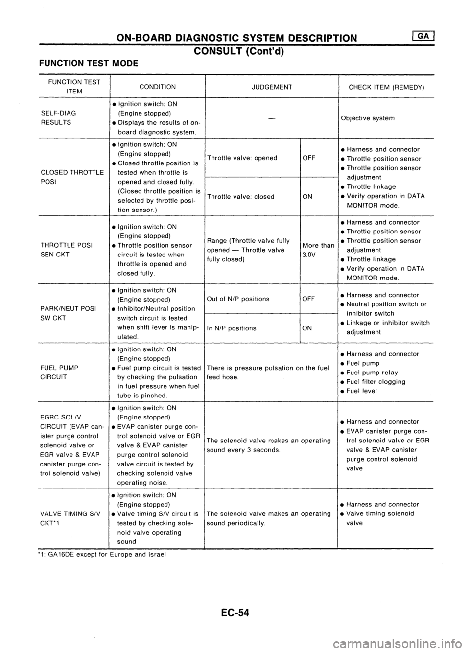
ON-BOARDDIAGNOSTIC SYSTEMDESCRIPTION
CONSULT (Cont'd)
FUNCTION TESTMODE
FUNCTION TEST
CONDITION
ITEM JUDGEMENT
CHECKITEM(REMEDY)
• Ignition switch:ON
SELF-DIAG (Enginestopped)
RESULTS
-
Objective
system
• Displays theresults ofon-
board diagnostic system.
• Ignition switch:ON
•Harness andconnector
(Engine stopped)
Throttlevalve:opened OFF
•Throllle position sensor
• Closed throllle position is
•Throllie position sensor
CLOSED THROTTLE
testedwhenthrottle is
POSI openedandclosed fully. adjustment
(Closed throllieposition is •
Throttle linkage
selected bythrottle posi- Throttle
valve:closed
ON•
Verify operation inDATA
tion sensor.) MONITOR
mode.
• Ignition switch:ON •
Harness andconnector
(Engine stopped) •
Throttle position sensor
THROTTLE POSI•Throllle position sensor Range
(Throllle valvefully
Morethan •
Throllle position sensor
SEN CKT
circuitistested when opened
-Throllle valve
3.DV adjustment
throllie isopened and fully
closed) •Throllie linkage
closed fully. •
Verify operation inDATA
MONITOR mode.
• Ignition switch:ON
•Harness andconnector
(Engine stopoed) Out
ofNIP positions OFF
PARK/NEUT POSI
•Inhibitor/NelJlral position •
Neutral position switchor
SW CKT switchcircuit istested inhibitor
switch
when shiftlever ismanip-
InNIP positions ON•
Linkage orinhibitor switch
ulated . adjustment
• Ignition switch:ON
•Harness andconnector
(Engine stopped)
•Fuel pump
FUEL PUMP •Fuel pump circuit istested
Thereispressure pulsation onthe fuel
•Fuel pump relay
CIRCUIT bychecking thepulsation feedhose.
in fuel pressure whenfuel •
Fuel filter clogging
tube ispinched . •
Fuel level
• Ignition switch:ON
EGRC SOllV (Engine
stopped)
•Harness andconnector
CIRCUIT (EVAPcan-•EVAP canister purgecon-
•EVAP canister purgecon-
ister purge control trolsolenoid valveorEGR
Thesolenoid valvemakes anoperating trolsolenoid valveorEGR
solenoid valveor
valve
&
EVAP canister
soundevery3seconds. valve
&
EVAP canister
EGR valve
&
EVAP purgecontrol solenoid
purgecontrol solenoid
canister purgecon- valvecircuit istested by
valve
trol solenoid valve) checkingsolenoidvalve
operating noise.
• Ignition switch:ON
(Engine stopped) •
Harness andconnector
VALVE TIMING SIV•Valve timing SIVcircuit isThe
solenoid valvemakes anoperating •
Valve timing solenoid
CKT*1 testedbychecking sole-soundperiodically. valve
noid valve operating
sound
'1: GA16DE exceptforEurope andIsrael
EC-54